wheel torque MAZDA MIATA 1991 Factory Service Manual
[x] Cancel search | Manufacturer: MAZDA, Model Year: 1991, Model line: MIATA, Model: MAZDA MIATA 1991Pages: 392, PDF Size: 29.45 MB
Page 129 of 392
ADJUSTMENTS
CLOCKSPRING CENTERING
Set front wheels in straight-ahead position. Turn clockspring connector clockwise until it stops (do not force).
Return connector 2 3/4 turns counterclockwise. Rotate clockspring connector further, if necessary, to align
marks on connector and outer housing.
DISPOSAL PROCEDURES
DEPLOYED AIR BAG
Dispose deployed air bag module as you would any other part. Wear gloves and safety glasses when handling
air bag module.
SCRAPPED VEHICLE
1. Ensure vehicle is outside, and away from other vehicles and people. Open convertible top and doors.
Disconnect negative battery cable.
2. Ensure air bag module is firmly mounted to steering wheel. Remove knee protector and disconnect
Orange and Blue clockspring connectors at base of steering column. See Fig. 1
. Cut clockspring
connector Blue wires.
3. Connect 2 jumper wires (20 feet long) to cut clockspring wires. Connect other ends of wires to a 12-volt
battery to deploy air bag. Because of heat, wait 10 MINUTES before touching deployed air bag.
REMOVAL & INSTALLATION
CRASH SENSORS NOTE: Perform the following procedures when scrapping a vehicle with undeployed air
bag.
WARNING:Follow air bag service precautions to prevent accidentalair bag
deployment and personal injury. See SERVICE PRECAUTIONS.
NOTE: After component replacement, check system to ensure proper operation. See
SYSTEM OPERATION CHECK.
NOTE: Crash sensor orientation and mounting is important for proper operation. All
sensors must be positioned so that arrow points forward. If there is sheet metal
damage near sensor mounting point, inspect body structure at sensor
mounting point for deformation. If damaged, restore to original shape. Ensure
sensor mounting bolts or nuts are tightened to specification. See TORQUE
SPECIFICATIONS table.
1991 Mazda MX-5 Miata
AIR BAG RESTRAINT SYSTEM MAZDA 1990-91 AIR BAGS
Microsoft
Sunday, July 05, 2009 2:11:16 PMPage 4 © 2005 Mitchell Repair Information Company, LLC.
Page 132 of 392
ACTIVATING AIR BAG SYSTEM. Check AIR BAG indicator light to ensure system is functioning properly.
See SYSTEM OPERATION CHECK.
AIR BAG MODULE
Removal & Installation
1. Before proceeding, follow air bag service precautions. See SERVICE PRECAUTIONS. Disable air bag
system. See DISABLING & ACTIVATING AIR BAG SYSTEM.
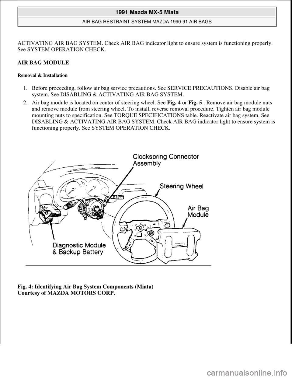
2. Air bag module is located on center of steering wheel. See Fig. 4
or Fig. 5 . Remove air bag module nuts
and remove module from steering wheel. To install, reverse removal procedure. Tighten air bag module
mounting nuts to specification. See TORQUE SPECIFICATIONS table. Reactivate air bag system. See
DISABLING & ACTIVATING AIR BAG SYSTEM. Check AIR BAG indicator light to ensure system is
functioning properly. See SYSTEM OPERATION CHECK.
Fig. 4: Identifying Air Bag System Components (Miata)
Courtesy of MAZDA MOTORS CORP.
1991 Mazda MX-5 Miata
AIR BAG RESTRAINT SYSTEM MAZDA 1990-91 AIR BAGS
Microsoft
Sunday, July 05, 2009 2:11:16 PMPage 7 © 2005 Mitchell Repair Information Company, LLC.
Page 133 of 392
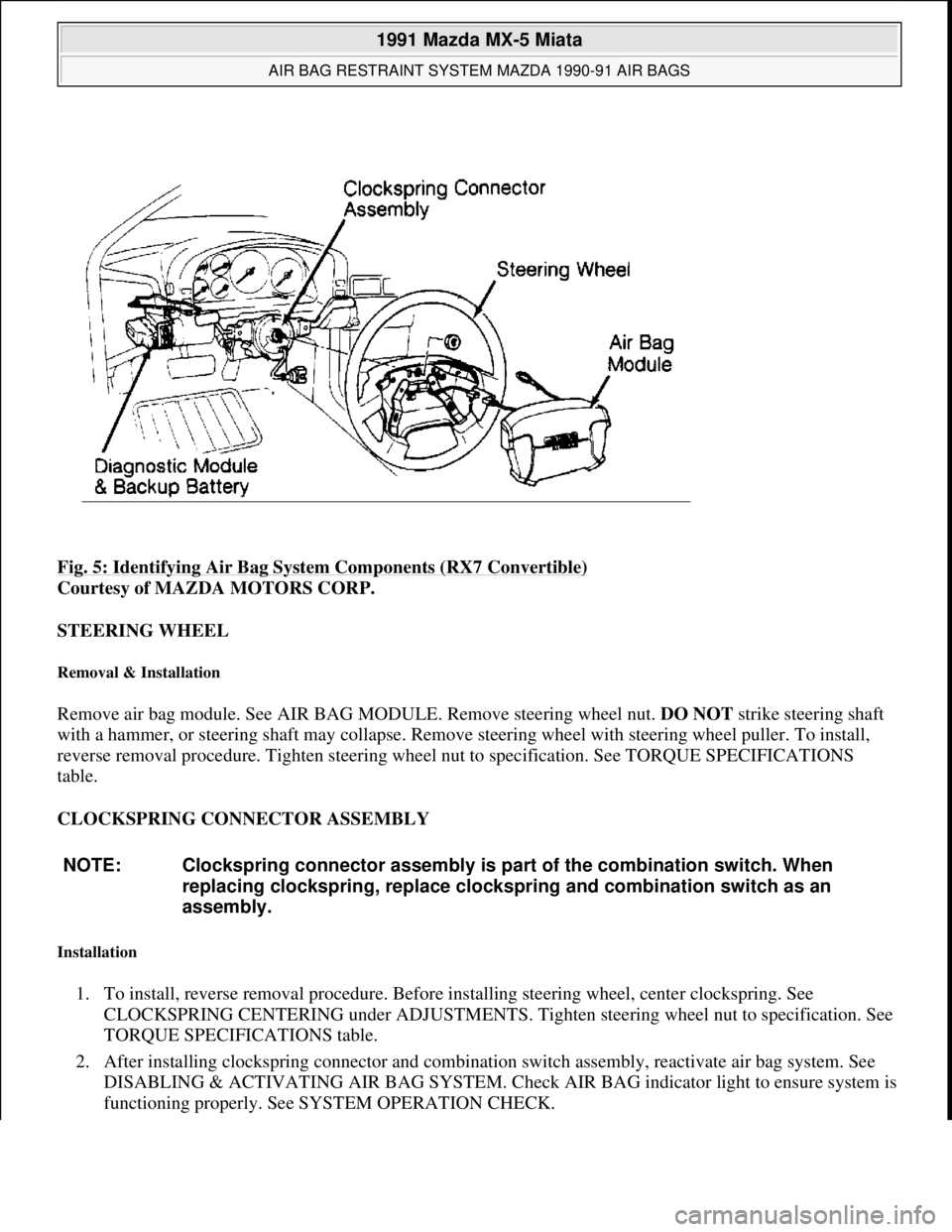
Fig. 5: Identifying Air Bag System Components (RX7 Convertible)
Courtesy of MAZDA MOTORS CORP.
STEERING WHEEL
Removal & Installation
Remove air bag module. See AIR BAG MODULE. Remove steering wheel nut. DO NOT strike steering shaft
with a hammer, or steering shaft may collapse. Remove steering wheel with steering wheel puller. To install,
reverse removal procedure. Tighten steering wheel nut to specification. See TORQUE SPECIFICATIONS
table.
CLOCKSPRING CONNECTOR ASSEMBLY
Installation
1. To install, reverse removal procedure. Before installing steering wheel, center clockspring. See
CLOCKSPRING CENTERING under ADJUSTMENTS. Tighten steering wheel nut to specification. See
TORQUE SPECIFICATIONS table.
2. After installing clockspring connector and combination switch assembly, reactivate air bag system. See
DISABLING & ACTIVATING AIR BAG SYSTEM. Check AIR BAG indicator light to ensure system is
functionin
g properly. See SYSTEM OPERATION CHECK.
NOTE: Clockspring connector assembly is part of the combination switch. When
replacing clockspring, replace clockspring and combination switch as an
assembly.
1991 Mazda MX-5 Miata
AIR BAG RESTRAINT SYSTEM MAZDA 1990-91 AIR BAGS
Microsoft
Sunday, July 05, 2009 2:11:16 PMPage 8 © 2005 Mitchell Repair Information Company, LLC.
Page 134 of 392
Removal
1. Before proceeding, follow air bag service precautions. See SERVICE PRECAUTIONS. Disable air bag
system. See DISABLING & ACTIVATING AIR BAG SYSTEM.
2. Clockspring connector assembly is located under steering wheel, in steering column. See Fig. 4
or Fig. 5.
Remove air bag module. See AIR BAG MODULE. Remove steering wheel nut and remove steering
wheel with steering wheel puller. Remove column covers. Remove screws. Remove clockspring
connector and combination switch as an assembly.
DIAGNOSTIC MODULE & BACK-UP BATTERY
Removal & Installation
1. Before proceeding, follow air bag service precautions. See SERVICE PRECAUTIONS. Disable air bag
system. See DISABLING & ACTIVATING AIR BAG SYSTEM.
2. Diagnostic module and back-up battery is located under left side of instrument panel. See Fig. 4
or Fig.
5 . Disconnect diagnostic module and back-up battery connectors. Remove nuts. Remove diagnostic
module and back-up battery as an assembly. To install, reverse removal procedure. After diagnostic
module and back-up battery are installed, reactivate air bag system. See DISABLING & ACTIVATING
AIR BAG SYSTEM. Check AIR BAG indicator light to ensure system is functioning properly. See
SYSTEM OPERATION CHECK.
SYSTEM OPERATION CHECK
Turn ignition switch to the ON or START position. AIR BAG warning light in instrument cluster should
illuminate for approximately 6 seconds then go out. This indicates that the air bag system is functioning
properly. If any of the following conditions exists, air bag system is malfunctioning and needs repair.
AIR BAG warning light does not illuminate as described.
AIR BAG warning light stays on for more than 6 seconds.
AIR BAG warning light illuminates while driving.
If air bag system components are replaced for any reason, air bag system must be checked for proper function
after repair. Turn ignition on. AIR BAG warning light should illuminate for approximately 6 seconds then go
out. If AIR BAG warning light does not illuminate as described, air bag system is malfunctioning and needs
repair. If warning light functions as described, check horn operation. If horn does not sound, remove air bag
module and check air bag module and horn switch connections. Always follow service precautions and
deactivate air bag system before performing repairs. See DISABLING & ACTIVATING AIR BAG
SYSTEM .
WIRE REPAIR
DO NOT repair air bag system wiring. If air bag harness connectors are faulty, replace faulty wiring harness.
TORQUE SPECIFICATIONS
1991 Mazda MX-5 Miata
AIR BAG RESTRAINT SYSTEM MAZDA 1990-91 AIR BAGS
Microsoft
Sunday, July 05, 2009 2:11:16 PMPage 9 © 2005 Mitchell Repair Information Company, LLC.
Page 135 of 392
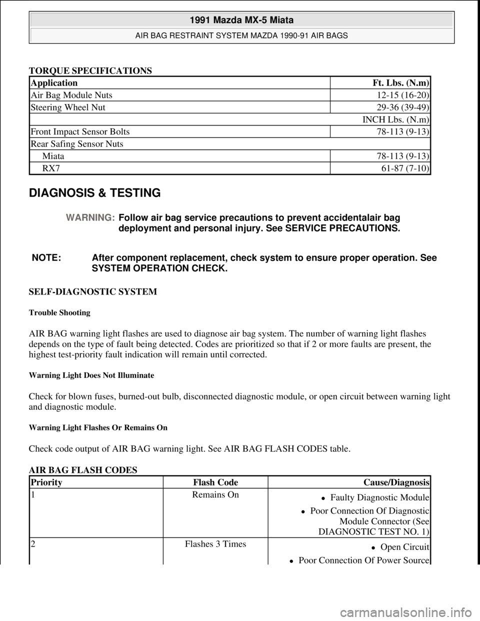
TORQUE SPECIFICATIONS
DIAGNOSIS & TESTING
SELF-DIAGNOSTIC SYSTEM
Trouble Shooting
AIR BAG warning light flashes are used to diagnose air bag system. The number of warning light flashes
depends on the type of fault being detected. Codes are prioritized so that if 2 or more faults are present, the
highest test-priority fault indication will remain until corrected.
Warning Light Does Not Illuminate
Check for blown fuses, burned-out bulb, disconnected diagnostic module, or open circuit between warning light
and diagnostic module.
Warning Light Flashes Or Remains On
Check code output of AIR BAG warning light. See AIR BAG FLASH CODES table.
AIR BAG FLASH CODES
ApplicationFt. Lbs. (N.m)
Air Bag Module Nuts12-15 (16-20)
Steering Wheel Nut29-36 (39-49)
INCH Lbs. (N.m)
Front Impact Sensor Bolts78-113 (9-13)
Rear Safing Sensor Nuts
Miata78-113 (9-13)
RX761-87 (7-10)
WARNING:Follow air bag service precautions to prevent accidentalair bag
deployment and personal injury. See SERVICE PRECAUTIONS.
NOTE: After component replacement, check system to ensure proper operation. See
SYSTEM OPERATION CHECK.
PriorityFlash CodeCause/Diagnosis
1Remains OnFaulty Diagnostic Module
Poor Connection Of Diagnostic
Module Connector (See
DIAGNOSTIC TEST NO. 1)
2Flashes 3 TimesOpen Circuit
Poor Connection Of Power Source
1991 Mazda MX-5 Miata
AIR BAG RESTRAINT SYSTEM MAZDA 1990-91 AIR BAGS
Microsoft
Sunday, July 05, 2009 2:11:16 PMPage 10 © 2005 Mitchell Repair Information Company, LLC.
Page 166 of 392
WHEEL SPEED SENSOR ROTORS
Inspection
Perform a comprehensive visual inspection of sensor rotor. If any damage is noted, replace sensor rotor. Sensor
rotors are attached to wheel hubs.
REMOVAL & INSTALLATION
HYDRAULIC UNIT
Removal
Remove hydraulic lines from unit. Disconnect hydraulic unit connectors. Remove nuts securing unit. Remove
hydraulic unit.
Bleeding Hydraulic Unit
Before bleeding hydraulic unit, bleed brake system in appropriate sequence. See BRAKE LINE BLEEDING
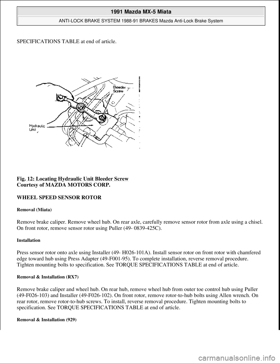
SEQUENCE TABLE under BLEEDING BRAKE SYSTEM. Bleed hydraulic unit by opening bleeder screw on
unit. See Fig. 12
.
Installation
To install, reverse removal procedure. Tighten mounting bolts to specification. See TORQUE
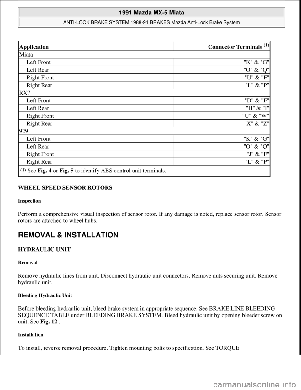
ApplicationConnector Terminals (1)
Miata
Left Front"K" & "G"
Left Rear"O" & "Q"
Right Front"U" & "F"
Right Rear"L" & "P"
RX7
Left Front"D" & "F"
Left Rear"H" & "I"
Right Front"U" & "W"
Right Rear"X" & "Z"
929
Left Front"K" & "G"
Left Rear"O" & "Q"
Right Front"J" & "F"
Right Rear"L" & "P"
(1)See Fig. 4 or Fig. 5 to identify ABS control unit terminals.
1991 Mazda MX-5 Miata
ANTI-LOCK BRAKE SYSTEM 1988-91 BRAKES Mazda Anti-Lock Brake System
Microsoft
Sunday, July 05, 2009 2:17:32 PMPage 14 © 2005 Mitchell Repair Information Company, LLC.
Page 167 of 392
SPECIFICATIONS TABLE at end of article.
Fig. 12: Locating Hydraulic Unit Bleeder Screw
Courtesy of MAZDA MOTORS CORP.
WHEEL SPEED SENSOR ROTOR
Removal (Miata)
Remove brake caliper. Remove wheel hub. On rear axle, carefully remove sensor rotor from axle using a chisel.
On front rotor, remove sensor rotor using Puller (49- 0839-425C).
Installation
Press sensor rotor onto axle using Installer (49- H026-101A). Install sensor rotor on front rotor with chamfered
edge toward hub using Press Adapter (49-F001-95). To complete installation, reverse removal procedure.
Tighten mounting bolts to specification. See TORQUE SPECIFICATIONS TABLE at end of article.
Removal & Installation (RX7)
Remove brake caliper and wheel hub. On rear hub, remove wheel hub from outer toe control hub using Puller
(49-F026-103) and Installer (49-F026-102). On front rotor, remove rotor-to-hub bolts using Allen wrench. On
rear rotor, remove rotor-to-hub screws. To install, reverse removal procedure. Tighten mounting bolts to
specification. See TORQUE SPECIFICATIONS TABLE at end of article.
Removal & Installation (929)
1991 Mazda MX-5 Miata
ANTI-LOCK BRAKE SYSTEM 1988-91 BRAKES Mazda Anti-Lock Brake System
Microsoft
Sunday, July 05, 2009 2:17:32 PMPage 15 © 2005 Mitchell Repair Information Company, LLC.
Page 168 of 392
Remove brake caliper and wheel hub. On rear axle, carefully remove sensor rotor from axle using chisel. On
front rotor, remove sensor rotor using Puller (49-0839-425C). To install, press sensor rotors onto axle and front
rotor using Installer (49-H026-101A). On front rotor, install sensor rotor with chamfered edge toward hub. To
complete installation, reverse removal procedure. Tighten mounting bolts to specification. See TORQUE
SPECIFICATIONS TABLE at end of article.
WHEEL SPEED SENSOR
Removal & Installation
Unplug wheel sensor connector. Remove sensor bolt. Remove wheel sensor from vehicle. To install, reverse
removal procedure. On RX7, adjust wheel sensor so clearance between sensor and rotor is .016-.039" (.40-1.0
mm). Tighten mounting bolts to specification. See TORQUE SPECIFICATIONS TABLE at end of article.
DIAGNOSING ABS SYSTEM
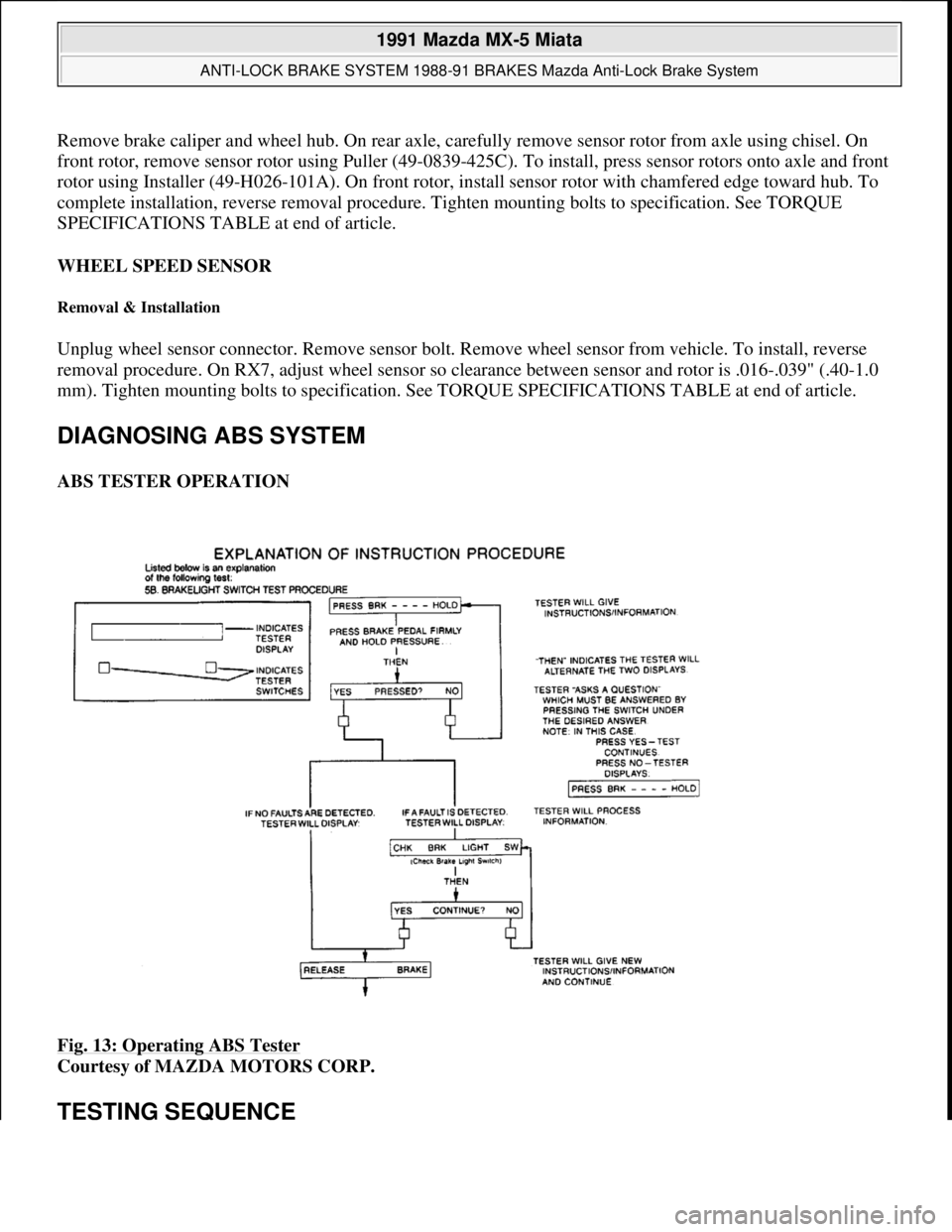
ABS TESTER OPERATION
Fig. 13: Operating ABS Tester
Courtesy of MAZDA MOTORS CORP.
TESTING SEQUENCE
1991 Mazda MX-5 Miata
ANTI-LOCK BRAKE SYSTEM 1988-91 BRAKES Mazda Anti-Lock Brake System
Microsoft
Sunday, July 05, 2009 2:17:32 PMPage 16 © 2005 Mitchell Repair Information Company, LLC.
Page 190 of 392
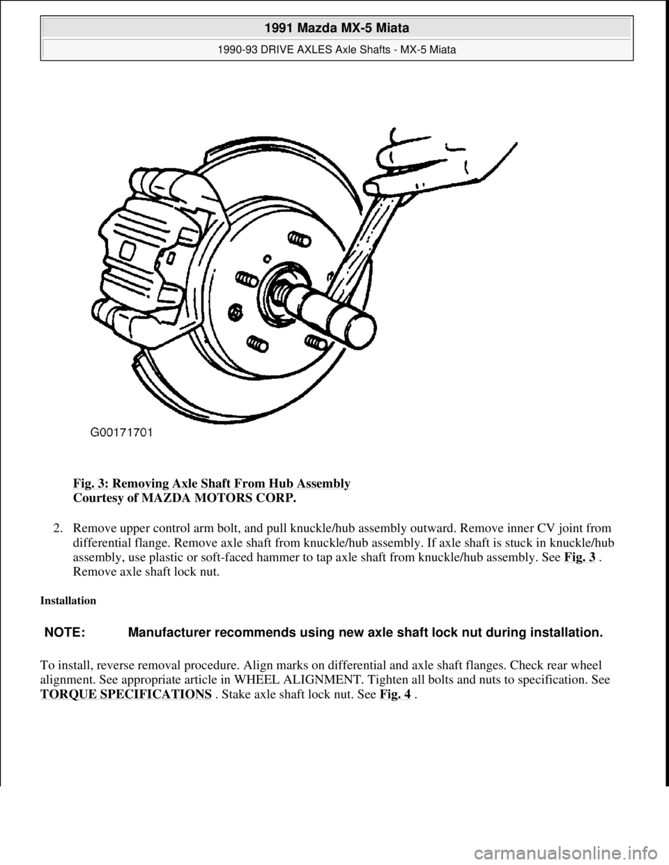
Fig. 3: Removing Axle Shaft From Hub Assembly
Courtesy of MAZDA MOTORS CORP.
2. Remove upper control arm bolt, and pull knuckle/hub assembly outward. Remove inner CV joint from
differential flange. Remove axle shaft from knuckle/hub assembly. If axle shaft is stuck in knuckle/hub
assembly, use plastic or soft-faced hammer to tap axle shaft from knuckle/hub assembly. See Fig. 3
.
Remove axle shaft lock nut.
Installation
To install, reverse removal procedure. Align marks on differential and axle shaft flanges. Check rear wheel
alignment. See appropriate article in WHEEL ALIGNMENT. Tighten all bolts and nuts to specification. See
TORQUE SPECIFICATIONS
. Stake axle shaft lock nut. See Fig. 4.
NOTE: Manufacturer recommends using new axle shaft lock nut during installation.
1991 Mazda MX-5 Miata
1990-93 DRIVE AXLES Axle Shafts - MX-5 Miata
Microsoft
Sunday, July 05, 2009 2:16:33 PMPage 4 © 2005 Mitchell Repair Information Company, LLC.
Page 202 of 392
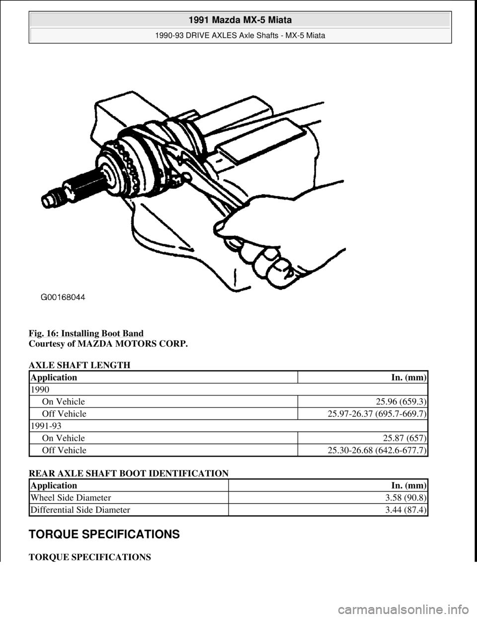
Fig. 16: Installing Boot Band
Courtesy of MAZDA MOTORS CORP.
AXLE SHAFT LENGTH
REAR AXLE SHAFT BOOT IDENTIFICATION
TORQUE SPECIFICATIONS
TORQUE SPECIFICATIONS
ApplicationIn. (mm)
1990
On Vehicle25.96 (659.3)
Off Vehicle25.97-26.37 (695.7-669.7)
1991-93
On Vehicle25.87 (657)
Off Vehicle25.30-26.68 (642.6-677.7)
ApplicationIn. (mm)
Wheel Side Diameter3.58 (90.8)
Differential Side Diameter3.44 (87.4)
1991 Mazda MX-5 Miata
1990-93 DRIVE AXLES Axle Shafts - MX-5 Miata
Microsoft
Sunday, July 05, 2009 2:16:33 PMPage 16 © 2005 Mitchell Repair Information Company, LLC.