Fluid MAZDA MIATA 1997 Factory Owner's Manual
[x] Cancel search | Manufacturer: MAZDA, Model Year: 1997, Model line: MIATA, Model: MAZDA MIATA 1997Pages: 514, PDF Size: 17.89 MB
Page 199 of 514

MOTORS
MOTORS
SENDING UNITS & SENSORS
SENDING UNITS & SENSORS
Key Interlock UnitBehind left side of dash. See Fig. 2 .
SAS UnitBehind center of dash. See Fig. 2 .
Transmission Control Module (TCM)Under left side of dash, near fuse block. See Fig. 2 .
ComponentComponent Location
Blower MotorUnder right side of dash. See Fig. 2 .
Condenser Fan MotorIn front of engine compartment.
Cooling Fan MotorIn front of engine compartment.
Cruise Control ActuatorOn left side of engine compartment.
Fuel PumpIn fuel tank.
Power Antenna MotorIn right front of trunk.
Retractable Headlamp ActuatorsBehind respective headlamp.
Shift Lock ActuatorUnder center console, on base of gear selector.
Windshield Washer MotorOn bottom of washer fluid reservoir.
Windshield Wiper MotorOn right side of firewall.
ComponentComponent Location
ABS Wheel Speed Sensor (Left Front)On back of left front wheel spindle assembly. See Fig. 1 .
ABS Wheel Speed Sensor (Left Rear)On back of left rear wheel hub assembly. See Fig. 3 .
ABS Wheel Speed Sensor (Right Front)On back of right front wheel spindle assembly. See Fig. 1 .
ABS Wheel Speed Sensor (Right Rear)On back of right rear wheel hub assembly. See Fig. 3 .
Brake Fluid Level SensorIn brake fluid reservoir. See Fig. 1 .
Camshaft Position SensorIn center rear of engine compartment. See Fig. 1 .
Crankshaft Position SensorOn front of engine.
EGR Boost SensorOn right side of engine compartment.
EGR Valve Position SensorOn right side center, rear of engine compartment.
EGR Valve Position SensorOn right side center, rear of engine compartment. See Fig. 1 .
Engine Coolant Temperature SensorOn rear of engine. See Fig. 1 .
Fuel Gauge Sender UnitIn fuel tank.
Heated Oxygen Sensor (Front)In rear of engine compartment. See Fig. 1 .
Heated Oxygen Sensor (Rear)On underside of vehicle, on exhaust pipe.
Input/Turbine Speed SensorOn left side of transmission.
Mass Air Flow SensorOn top of air filter housing. See Fig. 1 .
Throttle Position (TP) SensorOn side of throttle body. See Fig. 1 .
Transmission Fluid Temperature SensorOn left side of transmission.
1997 Mazda MX-5 Miata
1997 MAZDA MX-5 Miata
Microsoft
Sunday, July 05, 2009 1:54:00 PMPage 2 © 2005 Mitchell Repair Information Company, LLC.
Page 200 of 514

SOLENOIDS & SOLENOID VALVES
SOLENOIDS & SOLENOID VALVES
SWITCHES
SWITCHES
MISCELLANEOUS
MISCELLANEOUS
Vehicle Speed Sensor (VSS)On speedometer assembly.
Water Temperature Sender UnitOn center of engine. See Fig. 1 .
Washer Fluid Level SensorOn washer fluid reservoir. See Fig. 1 .
ComponentComponent Location
AT Interlock SolenoidIn steering column, near ignition switch. See Fig. 2 .
EC-AT Solenoid ValveOn left side of transmission.
EGR Solenoid Valve (Vacuum)On right side of engine compartment. See Fig. 1 .
EGR Solenoid Valve (Vent)On right side of engine compartment. See Fig. 1 .
Fourth Gear Solenoid ValveOn left side of transmission.
Idle Air Control ValveOn right side, front of engine compartment. See Fig. 1 .
PRC Solenoid ValveOn right side, front of engine. See Fig. 1 .
Purge Solenoid ValveOn right strut tower. See Fig. 1 .
ComponentComponent Location
Back-Up Lamp Switch (M/T)On right side of transmission. See Fig. 1 .
Brake SwitchOn bracket, above brake pedal. See Fig. 2 .
Buckle SwitchOn driver side seat belt buckle. See Fig. 3 .
Clutch Switch (M/T)On bracket, above clutch pedal. See Fig. 2 .
Hold SwitchUnder right side of center console.
Key Reminder SwitchIn steering column, near ignition switch.
Neutral Switch (M/T)On right side of transmission. See Fig. 1 .
Oil Pressure SwitchOn right side of engine. See Fig. 1 .
"P" Range SwitchUnder center console, on base of gear selector.
Parking Brake SwitchOn base of parking brake lever. See Fig. 4 .
Power Steering Pressure SwitchOn power steering pump assembly.
Refrigerant Pressure SwitchIn front of engine compartment, near radiator support. See Fig. 1 .
Starter Interlock Switch (M/T)On bracket, above clutch pedal. See Fig. 2 .
ThermoswitchUnder right side of dash.
Transmission Range SwitchOn left side of transmission.
ComponentComponent Location
1997 Mazda MX-5 Miata
1997 MAZDA MX-5 Miata
Microsoft
Sunday, July 05, 2009 1:54:00 PMPage 3 © 2005 Mitchell Repair Information Company, LLC.
Page 209 of 514

ENGINE
Removal (Miata)
1. Release residual pressure from fuel system. See FUEL PRESSURE RELEASE & PRIMING .
Disconnect negative battery cable from trunk-mounted battery. Reference mark and remove hood. Raise
vehicle and remove engine undercover. See Fig. 2
. Drain engine, transmission and cooling system fluids.
2. Remove transmission. For automatic transmission removal procedure, see REMOVAL &
INSTALLATION article in TRANSMISSION SERVICING. For manual transmission removal
procedure, see appropriate article in CLUTCHES. NOTE: On Miata with audio anti-theft system, radio will not operate if power to radio is
cut. Obtain code from customer to reactivate radio. To reactivate radio after
reconnecting power supply, turn ignition switch to ACC position. Press and
hold FF and REW buttons until CODE is displayed. Again press and hold FF and
REW buttons until bars (----) are displayed. Use preset button No. 1 to enter first
number. Use preset buttons No. 2 to enter second number, 3 for third number,
etc. Press FF and REW buttons for about 1.5 seconds until a beep is heard.
After 5 seconds, flashing CODE will disappear and radio will operate.
1997 Mazda MX-5 Miata
1997-98 ENGINES 1.8L 4-Cylinder
Microsoft
Sunday, July 05, 2009 1:55:15 PMPage 3 © 2005 Mitchell Repair Information Company, LLC.
Page 212 of 514
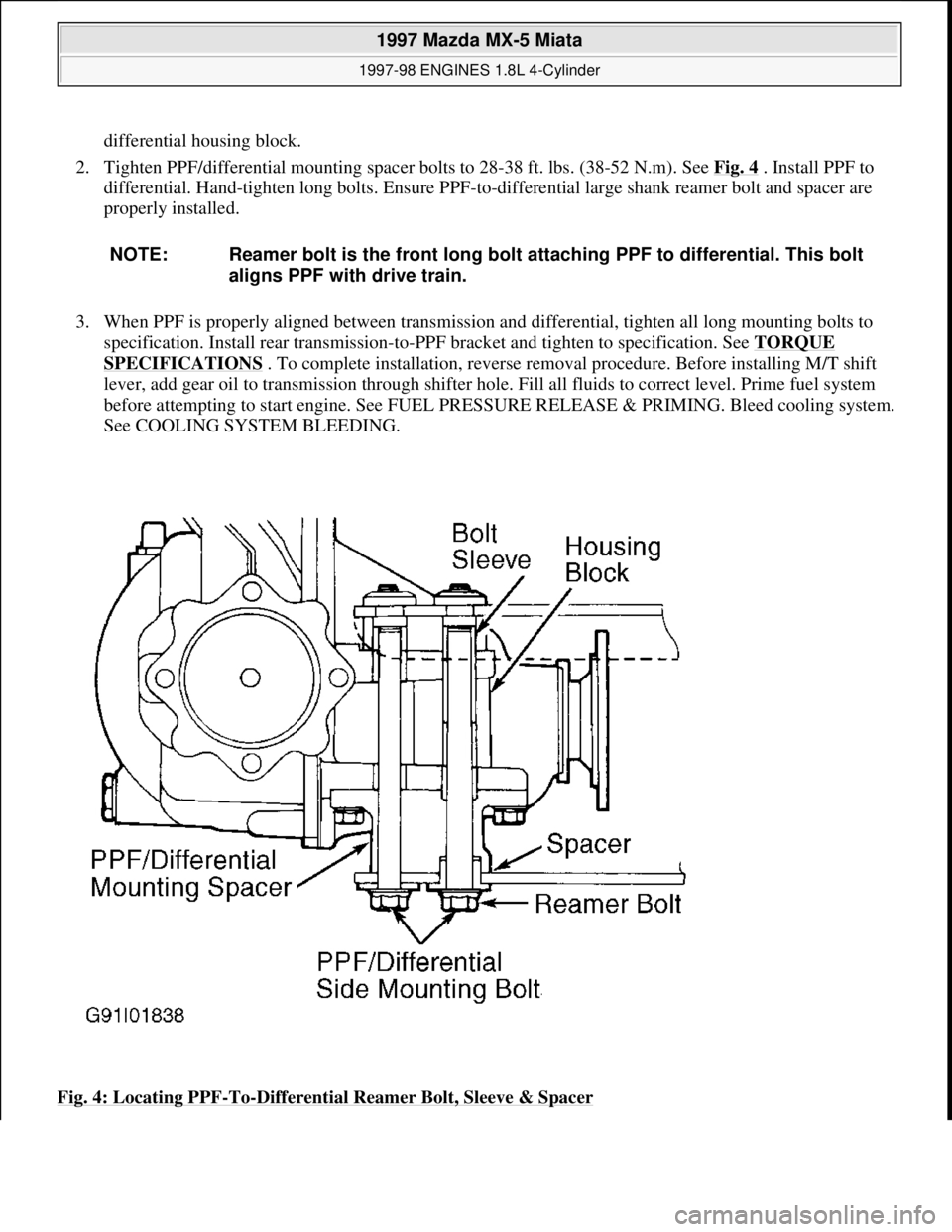
differential housing block.
2. Tighten PPF/differential mounting spacer bolts to 28-38 ft. lbs. (38-52 N.m). See Fig. 4
. Install PPF to
differential. Hand-tighten long bolts. Ensure PPF-to-differential large shank reamer bolt and spacer are
properly installed.
3. When PPF is properly aligned between transmission and differential, tighten all long mounting bolts to
specification. Install rear transmission-to-PPF bracket and tighten to specification. See TORQUE
SPECIFICATIONS . To complete installation, reverse removal procedure. Before installing M/T shift
lever, add gear oil to transmission through shifter hole. Fill all fluids to correct level. Prime fuel system
before attempting to start engine. See FUEL PRESSURE RELEASE & PRIMING. Bleed cooling system.
See COOLING SYSTEM BLEEDING.
Fig. 4: Locating PPF
-To-Differential Reamer Bolt, Sleeve & Spacer
NOTE: Reamer bolt is the front long bolt attaching PPF to differential. This bolt
aligns PPF with drive train.
1997 Mazda MX-5 Miata
1997-98 ENGINES 1.8L 4-Cylinder
Microsoft
Sunday, July 05, 2009 1:55:15 PMPage 6 © 2005 Mitchell Repair Information Company, LLC.
Page 213 of 514

Courtesy of MAZDA MOTORS CORP.
Removal & Installation (Protege)
1. Release residual pressure from fuel system. See FUEL PRESSURE RELEASE & PRIMING .
Disconnect negative battery cable. Reference mark and remove hood. Raise vehicle. Remove engine
undercover and side covers. See Fig. 5
. Drain engine, transaxle and cooling system fluids. Remove front
wheels.
1997 Mazda MX-5 Miata
1997-98 ENGINES 1.8L 4-Cylinder
Microsoft
Sunday, July 05, 2009 1:55:15 PMPage 7 © 2005 Mitchell Repair Information Company, LLC.
Page 214 of 514

Fig. 5: Removing Engine Components (Protege)
Courtesy of MAZDA MOTORS CORP.
2. Lower vehicle. Remove air cleaner assembly. Remove battery/carrier assembly. Remove throttle cable
and air intake duct across radiator (if equipped).
3. Remove all drive belts. DO NOT disconnect power steering hoses or A/C compressor hoses. Unbolt
power steering pump and A/C compressor from engine, and wire aside.
4. Note locations and disconnect all necessary electrical connectors, ground wires, vacuum hoses, fuel
hoses, coolant hoses and control cables for engine removal.
5. Plug all fuel hoses to avoid leakage. Attach engine support bar or engine hoist to secure engine. Raise
vehicle. Disconnect exhaust manifold down pipe and exhaust brackets from engine. On A/T models,
remove shift control cable.
6. On M/T models, remove shift control linkage and extension bar. Remove clutch release cylinder and fluid
line bracket from transaxle housing, leaving fluid line connected to cylinder. Secure cylinder away from
transaxle.
7. On all models, remove transmission wiring harness connectors and speedometer cable. Remove axle shaft
nuts from hubs. Disconnect stabilizer bar from lower control arms. Separate lower ball joints and steering
tie-rod ends from steering knuckles.
8. Pry axle shafts out of transaxle. Remove and discard circlip from axle shafts. For further information on
axle shafts, see appropriate article in DRIVE AXLES.
9. Remove transaxle mount nuts from crossmember and loosen crossmember bolts. See Fig. 6
. Lower
vehicle and attach engine hoist for engine removal. Remove engine front mount and transaxle top mount
from inner fender panels. Remove transaxle crossmember. Remove engine and transaxle assembly from
top of vehicle.
10. To install, reverse removal procedure. Tighten bolts and nuts to specifications. See TORQUE
SPECIFICATIONS . Fill all fluids to correct level. Prime fuel system before attempting to start engine.
See FUEL PRESSURE RELEASE & PRIMING
. Bleed cooling system. See COOLING SYSTEM
BLEEDING.
1997 Mazda MX-5 Miata
1997-98 ENGINES 1.8L 4-Cylinder
Microsoft
Sunday, July 05, 2009 1:55:15 PMPage 8 © 2005 Mitchell Repair Information Company, LLC.
Page 323 of 514

Cracks Or Tears In Belt Surface
Missing, Damaged, Cracked Or Rounded Teeth
Oil Contamination
Damaged Or Faulty Tensioners
Incorrect Tension Adjustment
SERVICE POINT LOCATIONS
Fig. 2: Service Point Locations
Courtesy of MAZDA MOTOR OF AMERICA, INC.
LUBRICATION SPECIFICATIONS
LUBRICATION SPECIFICATIONS
MaterialConditionSpecification
Engine Oil (1) Ambient Temperature Above -10°
F (-23°C) To Over 100°F (38°C)SAE 10W-30
Engine Oil (1) Ambient Temperature Less Than -
10°F (-23°C) To 60°F (16°C)SAE 5W-30
Engine CoolantAbove 3°F (-16°C) Above -15°F
(-26°C) Above -40°F (-40°C)35/65 Mixture 45/55 Mixture
55/45 Mixture Distilled Water
Ethylene Glycol
Brake FluidAllDOT 3
Automatic Transaxle FluidAllATF M-III or DEXRON II
Manual Transaxle FluidAllHypoid Gear Oil API
Classification GL-4 or GL-5 SAE
75W-90 Above 50°F (10°C):
80W-90
A/C RefrigerantAllR-134a
1997 Mazda MX-5 Miata
MAINTENANCE INFORMATION 1997 MAINTENANCE Mazda Maintenance Information
Microsoft
Sunday, July 05, 2009 1:41:19 PMPage 3 © 2005 Mitchell Repair Information Company, LLC.
Page 324 of 514

FLUID CAPACITIES
FLUID CAPACITIES
WHEEL & TIRE SPECIFICATIONS
WHEEL TIGHTENING
Tighten wheel lug nuts to 65-87 ft. lbs. (88-118 N.m).
BATTERY SPECIFICATIONS
Vehicle is equipped with a special 9 9/16" x 4 3/4" x 7 3/8" 12-volt battery that is vented to outside of vehicle.
CAUTIONS & WARNINGS
SUPPLEMENTAL RESTRAINT SYSTEM (AIR BAG)
Modifications or improper maintenance, including incorrect removal and installation of the Supplemental
Restraint System (SRS), can adversely affect system performance. DO NOT cover, obstruct or change the
steerin
g wheel horn pad in any way, as such action could cause improper function of the system. Use only plain
(1)Energy conserving oils are recommended, API classification SG", "SH".
ItemConditionSpecification (1)
Engine OilDrained, With Filter4.0 Qts. (3.8L)
Engine OilDrained3.8 Qts. (3.6L)
Engine CoolantDrained6.3 Qts. (6.0L)
Automatic Transaxle FluidCapacity7.1 Qts. (6.7L)
Manual Transaxle FluidCapacity2.1 Qts. (2.0L)
Rear Axle OilCapacity1.1 Qts. (l.0L)
A/C RefrigerantEvacuated1 lb. 3.4 oz. (0.6kg)
Fuel TankCapacity12.6 Gal. (48.0L)
(1)Capacities are recommended or calculated levels. Always use dipstick (if available) to measure level.
CAUTION: When battery is disconnected, vehicles equipped with computers may
lose memory data. When battery power is restored, driveability problems
may exist on some vehicles. These vehicles may require a relearn
procedure. See COMPUTER RELEARN PROCEDURES article in the
GENERAL INFORMATION Section.
NOTE: See the AIR BAG RESTRAINT SYSTEM article in the ACCESSORIES/SAFETY
EQUIPMENT Section.
1997 Mazda MX-5 Miata
MAINTENANCE INFORMATION 1997 MAINTENANCE Mazda Maintenance Information
Microsoft
Sunday, July 05, 2009 1:41:19 PMPage 4 © 2005 Mitchell Repair Information Company, LLC.
Page 325 of 514

water when cleaning the horn pad. Solvents or cleaners could adversely affect the air bag cover and cause
improper deployment of the system.
AIR CONDITIONING SERVICING
ANTI-LOCK BRAKE SYSTEM
On models equipped with anti-lock brake systems, ALWAYS observe the following cautions:
DO NOT attempt to bleed hydraulic system without first referring to the appropriate ANTI-LOCK
BRAKE SYSTEM article in the BRAKES Section.
DO NOT mix tire sizes. As long as tires remain close to the original diameter, increasing the width is
acceptable. Rolling diameter must be identical for all 4 tires. Some manufacturers recommend tires of the
same brand, style and type. Failure to follow this precaution may cause inaccurate wheel speed readings.
Use ONLY recommended brake fluids. DO NOT use silicone brake fluids in an ABS-equipped vehicle.
BATTERY WARNING WARNING:To avoid injury from accidental air bag deployment, read and carefully
follow all warnings and service precautions. See appropriate AIR BAG
RESTRAINT SYSTEM article in ACCESSORIES/SAFETY EQUIPMENT.
CAUTION: Disconnect negative battery cable before servicing any air bag system,
steering column or passenger side dash component. After any repair, turn
ignition key to the ON position from passenger's side of vehicle in case of
accidental air bag inflation
CAUTION: Avoid breathing R-134a refrigerant and PAG lubricant vapors, exposure
may irritate eyes, nose and throat. To remove R-134a from system use R-
134a recycling equipment that meets SAE J2210 specifications. If
accidental system discharge occurs, ventilate work area before resuming
service.
WARNING:R-134a service equipment or vehicle A/C systems SHOULD NOT be
pressure tested or leak tested with compressed air. Some mixtures of
air/R134a have shown to be combustible at elevated pressures. These
mixtures are dangerous and may cause fire and/or explosions. See AIR
CONDITIONING SERVICE article in GENERAL INFORMATION section.
CAUTION: The anti-lock brake system contains electronic equipment that can be
susceptible to interference caused by improperly installed or high output
radio transmitting equipment. Since this interference could cause the
possible loss of the anti-lock braking capability, such equipment should
be installed by qualified professionals.
1997 Mazda MX-5 Miata
MAINTENANCE INFORMATION 1997 MAINTENANCE Mazda Maintenance Information
Microsoft
Sunday, July 05, 2009 1:41:19 PMPage 5 © 2005 Mitchell Repair Information Company, LLC.
Page 333 of 514

1997-98 MANUAL TRANSMISSION SERVICING
Mazda
APPLICATION
TRANSMISSION APPLICATIONS
LUBRICATION
SERVICE INTERVALS
Fluid Inspection & Replacement
Check fluid level(s) at least once a year. Change transmission/transaxle and transfer case fluids every 60,000
miles for normal driving conditions and every 30,000 miles for severe driving conditions.
CHECKING FLUID LEVEL
Transaxle Fluid
Remove fill plug from transaxle. Fluid should be up to bottom of fill hole on side of case.
Transmission Fluid (RWD Models)
Remove fill plug from transmission. Fluid should be up to bottom of fill hole on side of case.
Transfer Case Fluid (4WD)
Remove fill plug from transfer case. Fluid should be up to bottom of fill hole on side of transfer case.
RECOMMENDED FLUID
FLUID SPECIFICATIONS
Vehicle ApplicationTransmission/Transaxle Model
B2300, B2500, B3000 & B4000M50D-R1
MiataM15M-D
MX-6 & 626G25M-R
ProtegeF25M-R
NOTE: Mazda B2300, B2500, B3000 and B4000 are referred to as B-Series throughout
this article.
ApplicationRecommended Fluid
Transmission
1997 Mazda MX-5 Miata
1997-98 MANUAL TRANSMISSION SERVICING Mazda
1997 Mazda MX-5 Miata
1997-98 MANUAL TRANSMISSION SERVICING Mazda
Microsoft
Sunday, July 05, 2009 1:37:16 PMPage 1 © 2005 Mitchell Repair Information Company, LLC.
Microsoft
Sunday, July 05, 2009 1:37:28 PMPage 1 © 2005 Mitchell Repair Information Company, LLC.