suspension MAZDA MIATA 1997 Factory Repair Manual
[x] Cancel search | Manufacturer: MAZDA, Model Year: 1997, Model line: MIATA, Model: MAZDA MIATA 1997Pages: 514, PDF Size: 17.89 MB
Page 122 of 514
MASTER CYLINDER
Removal & Installation
Disconnect fluid level sensor electrical connector at fluid reservoir. Disconnect and plug brake lines at master
cylinder to prevent entry of dirt and loss of fluid. Remove nuts attaching master cylinder to power brake unit.
Remove master cylinder from vehicle. To install master cylinder, reverse removal procedure. Bleed air from
system.
POWER BRAKE UNIT
Removal & Installation
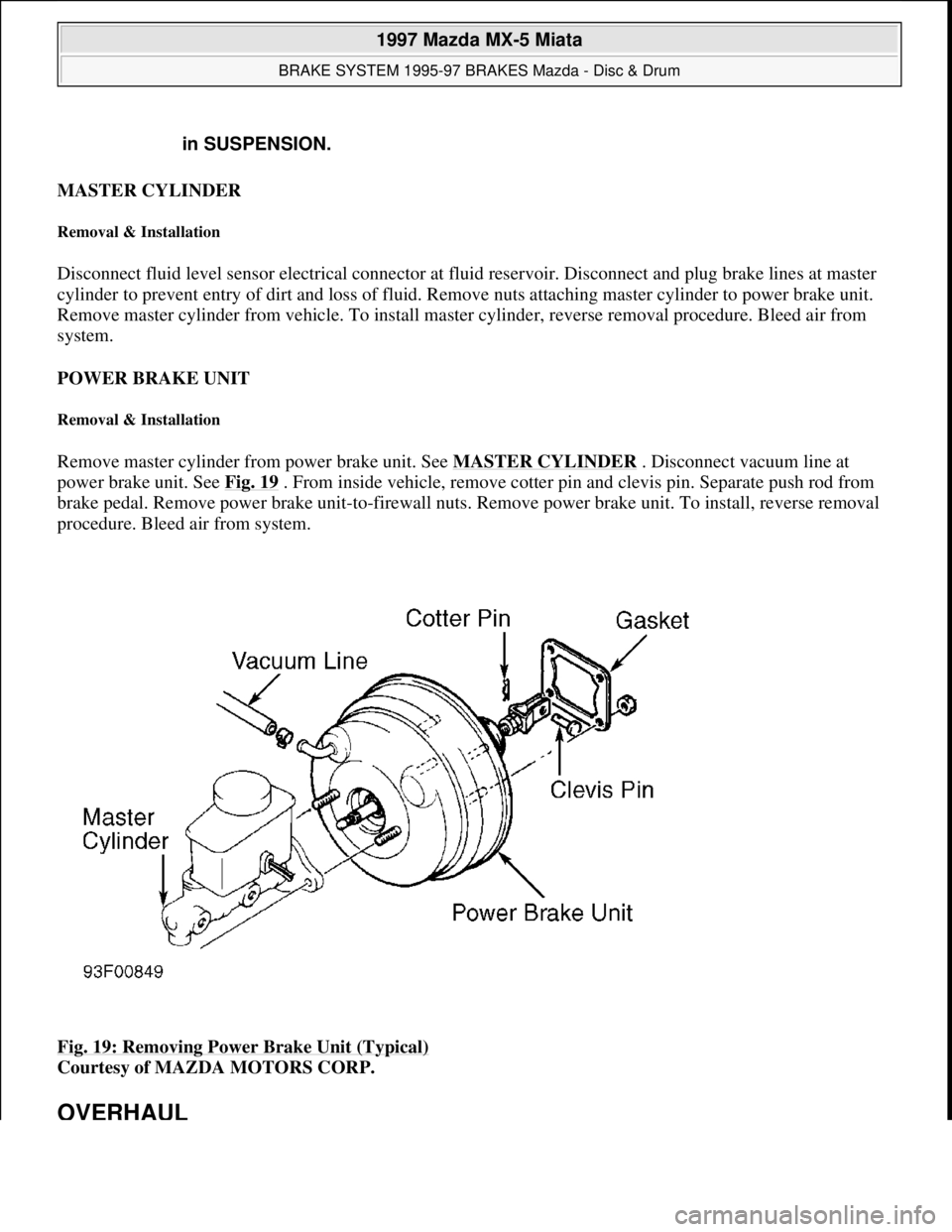
Remove master cylinder from power brake unit. See MASTER CYLINDER . Disconnect vacuum line at
power brake unit. See Fig. 19 . From inside vehicle, remove cotter pin and clevis pin. Separate push rod from
brake pedal. Remove power brake unit-to-firewall nuts. Remove power brake unit. To install, reverse removal
procedure. Bleed air from system.
Fig. 19: Removing Power Brake Unit (Typical)
Courtesy of MAZDA MOTORS CORP.
OVERHAUL
in SUSPENSION.
1997 Mazda MX-5 Miata
BRAKE SYSTEM 1995-97 BRAKES Mazda - Disc & Drum
Microsoft
Sunday, July 05, 2009 1:51:03 PMPage 28 © 2005 Mitchell Repair Information Company, LLC.
Page 175 of 514
1997-98 DRIVE AXLES
Differentials & Drive Axles - MPV & MX-5 Miata
AXLE RATIO & IDENTIFICATION
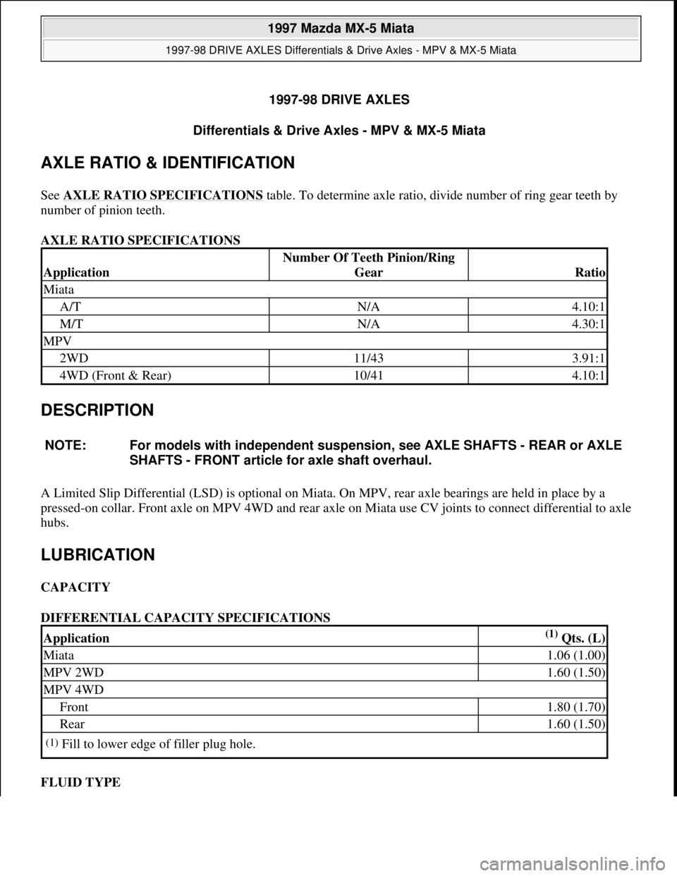
See AXLE RATIO SPECIFICATIONS table. To determine axle ratio, divide number of ring gear teeth by
number of pinion teeth.
AXLE RATIO SPECIFICATIONS
DESCRIPTION
A Limited Slip Differential (LSD) is optional on Miata. On MPV, rear axle bearings are held in place by a
pressed-on collar. Front axle on MPV 4WD and rear axle on Miata use CV joints to connect differential to axle
hubs.
LUBRICATION
CAPACITY
DIFFERENTIAL CAPACITY SPECIFICATIONS
FLUID TYPE
Application
Number Of Teeth Pinion/Ring
Gear
Ratio
Miata
A/TN/A4.10:1
M/TN/A4.30:1
MPV
2WD11/433.91:1
4WD (Front & Rear)10/414.10:1
NOTE: For models with independent suspension, see AXLE SHAFTS - REAR or AXLE
SHAFTS - FRONT article for axle shaft overhaul.
Application(1) Qts. (L)
Miata1.06 (1.00)
MPV 2WD1.60 (1.50)
MPV 4WD
Front1.80 (1.70)
Rear1.60 (1.50)
(1)Fill to lower edge of filler plug hole.
1997 Mazda MX-5 Miata
1997-98 DRIVE AXLES Differentials & Drive Axles - MPV & MX-5 Miata
1997 Mazda MX-5 Miata
1997-98 DRIVE AXLES Differentials & Drive Axles - MPV & MX-5 Miata
Microsoft
Sunday, July 05, 2009 1:52:42 PMPage 1 © 2005 Mitchell Repair Information Company, LLC.
Microsoft
Sunday, July 05, 2009 1:52:46 PMPage 1 © 2005 Mitchell Repair Information Company, LLC.
Page 288 of 514
1997-2000 SUSPENSION
Front - Miata
DESCRIPTION
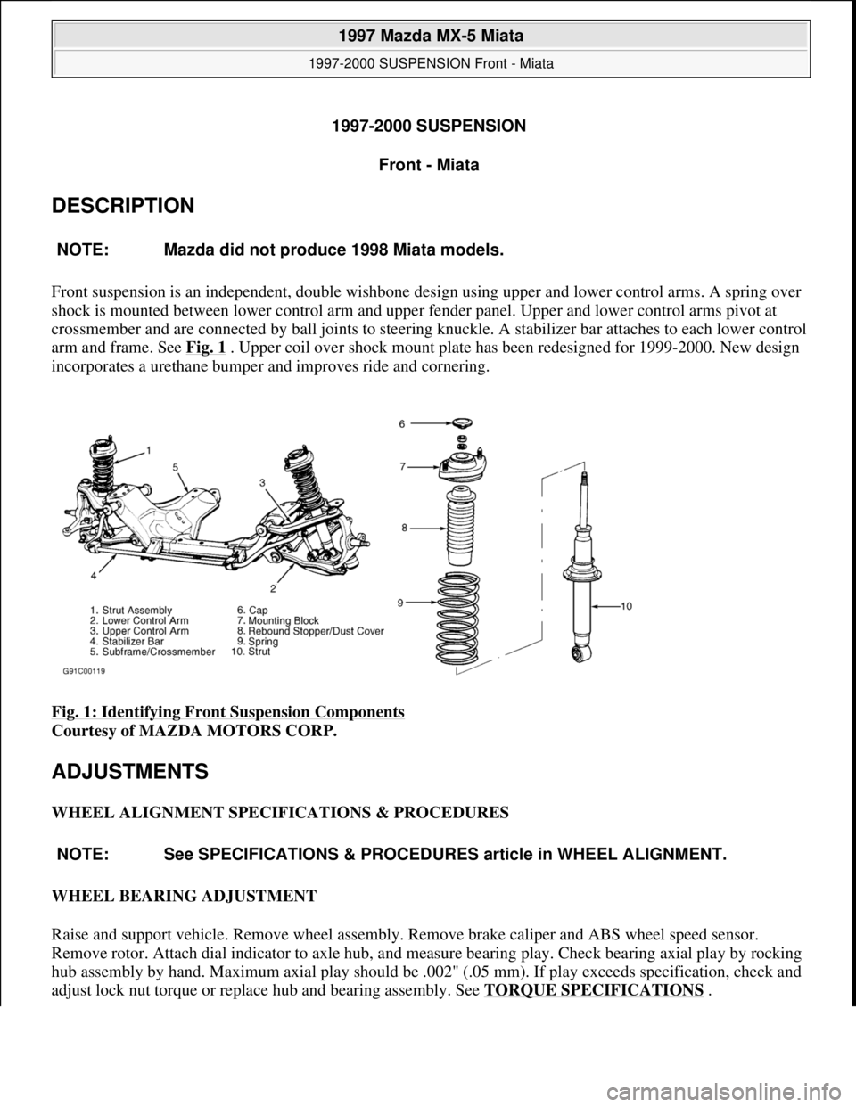
Front suspension is an independent, double wishbone design using upper and lower control arms. A spring over
shock is mounted between lower control arm and upper fender panel. Upper and lower control arms pivot at
crossmember and are connected by ball joints to steering knuckle. A stabilizer bar attaches to each lower control
arm and frame. See Fig. 1
. Upper coil over shock mount plate has been redesigned for 1999-2000. New design
incorporates a urethane bumper and improves ride and cornering.
Fig. 1: Identifying Front Suspension Components
Courtesy of MAZDA MOTORS CORP.
ADJUSTMENTS
WHEEL ALIGNMENT SPECIFICATIONS & PROCEDURES
WHEEL BEARING ADJUSTMENT
Raise and support vehicle. Remove wheel assembly. Remove brake caliper and ABS wheel speed sensor.
Remove rotor. Attach dial indicator to axle hub, and measure bearing play. Check bearing axial play by rocking
hub assembly by hand. Maximum axial play should be .002" (.05 mm). If play exceeds specification, check and
adjust lock nut torque or replace hub and bearing assembly. See TORQUE SPECIFICATIONS
. NOTE: Mazda did not produce 1998 Miata models.
NOTE: See SPECIFICATIONS & PROCEDURES article in WHEEL ALIGNMENT.
1997 Mazda MX-5 Miata
1997-2000 SUSPENSION Front - Miata
1997 Mazda MX-5 Miata
1997-2000 SUSPENSION Front - Miata
Microsoft
Sunday, July 05, 2009 1:38:08 PMPage 1 © 2005 Mitchell Repair Information Company, LLC.
Microsoft
Sunday, July 05, 2009 1:38:12 PMPage 1 © 2005 Mitchell Repair Information Company, LLC.
Page 289 of 514
INSPECTION
BALL JOINT CHECKING
Lower Ball Joint
Remove lower control arm. See LOWER CONTROL ARM & BALL JOINT under REMOVAL &
INSTALLATION. Rotate ball joint stud 4-5 times. Install Preload Attachment (49-0180-510B) to ball joint
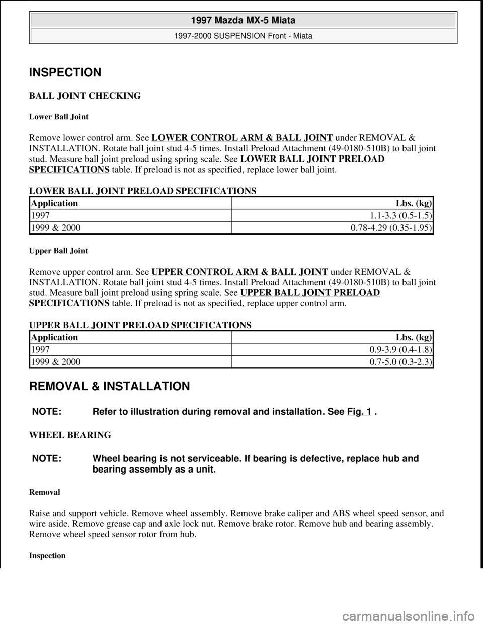
stud. Measure ball joint preload using spring scale. See LOWER BALL JOINT PRELOAD
SPECIFICATIONS table. If preload is not as specified, replace lower ball joint.
LOWER BALL JOINT PRELOAD SPECIFICATIONS
Upper Ball Joint
Remove upper control arm. See UPPER CONTROL ARM & BALL JOINT under REMOVAL &
INSTALLATION. Rotate ball joint stud 4-5 times. Install Preload Attachment (49-0180-510B) to ball joint
stud. Measure ball joint preload using spring scale. See UPPER BALL JOINT PRELOAD
SPECIFICATIONS table. If preload is not as specified, replace upper control arm.
UPPER BALL JOINT PRELOAD SPECIFICATIONS
REMOVAL & INSTALLATION
WHEEL BEARING
Removal
Raise and support vehicle. Remove wheel assembly. Remove brake caliper and ABS wheel speed sensor, and
wire aside. Remove grease cap and axle lock nut. Remove brake rotor. Remove hub and bearing assembly.
Remove wheel speed sensor rotor from hub.
Inspection
ApplicationLbs. (kg)
19971.1-3.3 (0.5-1.5)
1999 & 20000.78-4.29 (0.35-1.95)
ApplicationLbs. (kg)
19970.9-3.9 (0.4-1.8)
1999 & 20000.7-5.0 (0.3-2.3)
NOTE: Refer to illustration during removal and installation. See Fig. 1
.
NOTE: Wheel bearing is not serviceable. If bearing is defective, replace hub and
bearing assembly as a unit.
1997 Mazda MX-5 Miata
1997-2000 SUSPENSION Front - Miata
Microsoft
Sunday, July 05, 2009 1:38:08 PMPage 2 © 2005 Mitchell Repair Information Company, LLC.
Page 290 of 514
Check for damage, excessive wear and signs of bearing seizure. Inspect steering knuckle and hub for cracks,
scoring and rust. Check for damaged dust cover and poor fit with steering knuckle. Replace components as
necessary.
Installation
To install, reverse removal procedure. Adjust wheel bearing preload. See WHEEL BEARING
ADJUSTMENT under ADJUSTMENTS. Stake axle nut.
LOWER CONTROL ARM & BALL JOINT
Removal
1. Raise and support vehicle. Remove wheel assembly. Remove engine splash shield (if equipped). Separate
tie rod end from steering knuckle (as necessary). Remove stabilizer bar from lower control arm.
2. Remove shock lower mounting bolt and separate lower shock from lower control arm. Remove lower
control arm ball joint cotter pin and nut. Separate lower control arm ball joint stud from knuckle using
Puller (49 T028 3A0). Remove lower control arm pivot bolts and remove lower control arm.
Inspection
Check lower control arm for damage or cracks. Check bushings for deterioration and excessive wear. Check
ball joint for excessive wear. Examine dust boot for damage. Replace components as necessary.
Bushing Replacement
Cut or press old bushing from control arm. Coat NEW bushing with paraffin-based oil. Press new bushing into
control arm.
Installation (All Models)
To install, reverse removal procedure. Tighten lower control arm-to-frame bolts to specification with vehicle
resting on ground and suspension unloaded. See TORQUE SPECIFICATIONS
.
UPPER CONTROL ARM & BALL JOINT
Removal
Raise and support vehicle. Remove wheel assembly. Remove engine splash shield. Remove wheel speed sensor
harness band. Remove shock lower mounting bolt, and separate lower shock from lower control arm. Remove
upper control arm ball joint cotter pin and nut. Separate upper control arm ball joint stud from knuckle using
Puller (49-0118-850C). Remove upper control arm pivot bolts and remove upper control arm.
Inspection
Check upper control arm for damage or cracks. Check bushings for deterioration and excessive wear. Check
ball joint for excessive wear. Examine dust boot for damage. Replace components as necessary.
1997 Mazda MX-5 Miata
1997-2000 SUSPENSION Front - Miata
Microsoft
Sunday, July 05, 2009 1:38:08 PMPage 3 © 2005 Mitchell Repair Information Company, LLC.
Page 291 of 514
Bushing Replacement
Cut or press old bushing from control arm. Coat new bushing with paraffin-based oil. Press new bushing into
control arm.
Installation (All Models)
To install, reverse removal procedure. Tighten upper control arm pivot bolts to specification with vehicle
resting on ground and suspension unloaded. See TORQUE SPECIFICATIONS
.
SHOCK ASSEMBLY
Removal (1997)
Raise and support vehicle. Remove wheel assembly. Remove engine splash shield. Remove wheel speed sensor
harness band. Remove stabilizer link bolt. Remove upper control arm ball joint cotter pin and nut. Separate
upper control arm ball joint stud from knuckle using Puller (49-0118-850C). Loosen lower control arm pivot
bolts. Remove shock upper mount nuts and lower bolt. Move lower control arm just enough to remove shock
assembly. DO NOT damage brake line.
Removal (1999 & 2000)
Raise and support vehicle. Remove wheel assembly. Remove engine splash shield. Remove wheel speed sensor.
Remove stabilizer link bolt. Separate lower control arm ball joint stud from knuckle using Puller (49-T028-
3A0). Loosen lower control arm pivot bolts. Inside engine compartment, on 1999 models, remove strut bar. See
FRONT STRUT BAR (1999)
. On 2000 models, remove shock upper mount nuts. On all models, under car,
remove lower bolt. Move lower control arm just enough to remove shock assembly. DO NOT damage brake
line.
Disassembly
Clamp upper shock mount in vise. Loosen piston lock nut 2 turns only. Compress coil spring using coil spring
compressor. Remove piston lock nut. Slowly release compressor tension. Remove components. Remove coil
spring. Remove shock from vise.
Inspection
Check shock tube for damage, oil leakage and abnormal noise. Check rubber components for deterioration or
damage. Inspect coil spring for signs of fatigue or damage. Replace components as necessary.
Reassembly (1997)
Clamp shock in vise. Install coil spring and components in reverse order of disassembly. Ensure coil spring is
well seated in upper and lower spring seats. See Fig. 2
. Tighten piston rod nut. See TORQUE
SPECIFICATIONS .
1997 Mazda MX-5 Miata
1997-2000 SUSPENSION Front - Miata
Microsoft
Sunday, July 05, 2009 1:38:08 PMPage 4 © 2005 Mitchell Repair Information Company, LLC.
Page 292 of 514
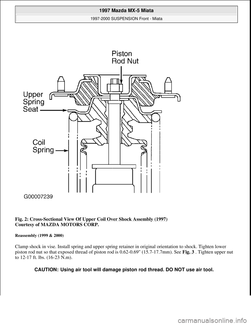
Fig. 2: Cross-Sectional View Of Upper Coil Over Shock Assembly (1997)
Courtesy of MAZDA MOTORS CORP.
Reassembly (1999 & 2000)
Clamp shock in vise. Install spring and upper spring retainer in original orientation to shock. Tighten lower
piston rod nut so that exposed thread of piston rod is 0.62-0.69" (15.7-17.7mm). See Fig. 3 . Tighten upper nut
to 12-17 ft. lbs. (16-23 N.m).
CAUTION: Using air tool will damage piston rod thread. DO NOT use air tool.
1997 Mazda MX-5 Miata
1997-2000 SUSPENSION Front - Miata
Microsoft
Sunday, July 05, 2009 1:38:08 PMPage 5 © 2005 Mitchell Repair Information Company, LLC.
Page 293 of 514
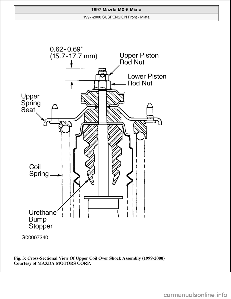
Fig. 3: Cross-Sectional View Of Upper Coil Over Shock Assembly (1999-2000)
Courtesy of MAZDA MOTORS CORP.
1997 Mazda MX-5 Miata
1997-2000 SUSPENSION Front - Miata
Microsoft
Sunday, July 05, 2009 1:38:08 PMPage 6 © 2005 Mitchell Repair Information Company, LLC.
Page 294 of 514
Installation
To install, reverse removal procedure. Fully tighten all bolts with vehicle resting on ground and suspension
unloaded. See TORQUE SPECIFICATIONS
. Check front wheel alignment. See SPECIFICATIONS &
PROCEDURES article in WHEEL ALIGNMENT.
STABILIZER BAR
Removal & Installation
Raise and support vehicle. Remove engine splash shield. Remove frame brackets and bushings. Remove
stabilizer control links. Align bushing with installation mark on stabilizer. Reverse removable procedure for
installation. See TORQUE SPECIFICATIONS
.
FRONT STRUT BAR (1999)
Removal & Installation
1. To remove strut bar located in engine compartment mounted on top of shock towers, loosen lock nuts on
joint bolt and loosen joint bolt. Remove nut, washer and bolt retaining strut bar to strut plate. Remove
strut bar from vehicle.
2. To install, reverse removal procedure. Rotate joint bolt counterclockwise to 3.5-5.2 INCH lbs. (.4-.6 N.m)
to set tension. Tighten lock nuts to 87-121 INCH lbs. (10-14 N.m). Tighten strut bar-to-strut plate nut.
See TORQUE SPECIFICATIONS
.
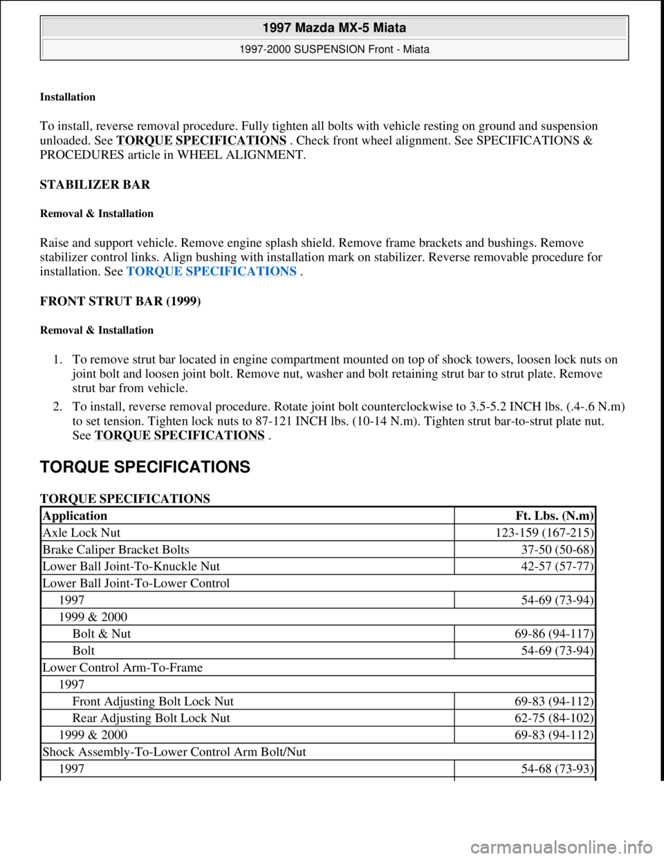
TORQUE SPECIFICATIONS
TORQUE SPECIFICATIONS
ApplicationFt. Lbs. (N.m)
Axle Lock Nut123-159 (167-215)
Brake Caliper Bracket Bolts37-50 (50-68)
Lower Ball Joint-To-Knuckle Nut42-57 (57-77)
Lower Ball Joint-To-Lower Control
199754-69 (73-94)
1999 & 2000
Bolt & Nut69-86 (94-117)
Bolt54-69 (73-94)
Lower Control Arm-To-Frame
1997
Front Adjusting Bolt Lock Nut69-83 (94-112)
Rear Adjusting Bolt Lock Nut62-75 (84-102)
1999 & 200069-83 (94-112)
Shock Assembly-To-Lower Control Arm Bolt/Nut
199754-68 (73-93)
1997 Mazda MX-5 Miata
1997-2000 SUSPENSION Front - Miata
Microsoft
Sunday, July 05, 2009 1:38:08 PMPage 7 © 2005 Mitchell Repair Information Company, LLC.
Page 295 of 514
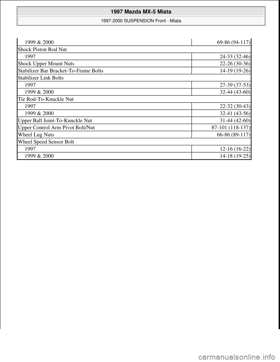
1999 & 200069-86 (94-117)
Shock Piston Rod Nut
199724-33 (32-46)
Shock Upper Mount Nuts22-26 (30-36)
Stabilizer Bar Bracket-To-Frame Bolts14-19 (19-26)
Stabilizer Link Bolts
199727-39 (37-53)
1999 & 200032-44 (43-60)
Tie Rod-To-Knuckle Nut
199722-32 (30-43)
1999 & 200032-41 (43-56)
Upper Ball Joint-To-Knuckle Nut31-44 (42-60)
Upper Control Arm Pivot Bolt/Nut87-101 (118-137)
Wheel Lug Nuts66-86 (89-117)
Wheel Speed Sensor Bolt
199712-16 (16-22)
1999 & 200014-18 (19-25)
1997 Mazda MX-5 Miata
1997-2000 SUSPENSION Front - Miata
Microsoft
Sunday, July 05, 2009 1:38:08 PMPage 8 © 2005 Mitchell Repair Information Company, LLC.