lights MAZDA MODEL B-SERIES 2002 (in English) User Guide
[x] Cancel search | Manufacturer: MAZDA, Model Year: 2002, Model line: MODEL B-SERIES, Model: MAZDA MODEL B-SERIES 2002Pages: 287, PDF Size: 2.47 MB
Page 82 of 287

2. Install the bulb retaining ring over the plastic base until it contacts
the rear of the socket by rotating clockwise until you feel a ªstop.º
3. Install the electrical connector into the plastic base until it snaps,
locking it into position.
4. Install the headlamp on vehicle, push rearward and secure with two
retainer pins.
5. Turn the headlamps on and make sure they work properly. If the
headlamp was correctly aligned before you changed the bulb, you
should not need to align it again.
Replacing front side marker bulbs
1. Open the hood.
2. At the back of the headlamp,
pry up the two retainer pins to
release the headlamp assembly
from the vehicle and pull
headlamp forward.
3. Remove screw(s) from lamp
assembly.
4. Disengage lamp assembly (it has
a snap fit).
Lights
82
Page 83 of 287

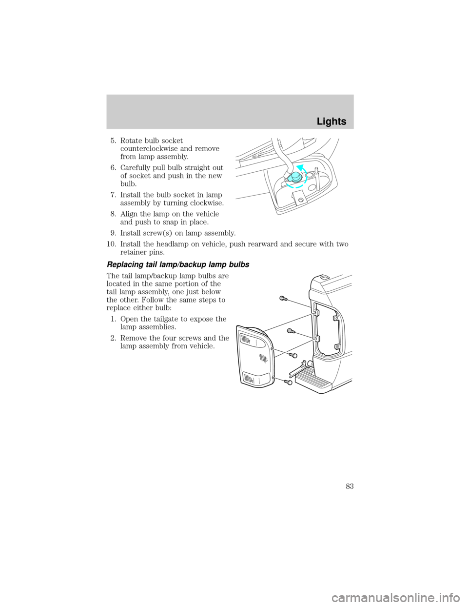
5. Rotate bulb socket
counterclockwise and remove
from lamp assembly.
6. Carefully pull bulb straight out
of socket and push in the new
bulb.
7. Install the bulb socket in lamp
assembly by turning clockwise.
8. Align the lamp on the vehicle
and push to snap in place.
9. Install screw(s) on lamp assembly.
10. Install the headlamp on vehicle, push rearward and secure with two
retainer pins.
Replacing tail lamp/backup lamp bulbs
The tail lamp/backup lamp bulbs are
located in the same portion of the
tail lamp assembly, one just below
the other. Follow the same steps to
replace either bulb:
1. Open the tailgate to expose the
lamp assemblies.
2. Remove the four screws and the
lamp assembly from vehicle.
Lights
83
Page 84 of 287

3. Rotate bulb socket
counterclockwise turn and
remove from lamp assembly.
4. Carefully pull the bulb straight
out of the socket and push in
the new bulb.
5. Install the bulb socket in lamp
assembly by turning clockwise.
6. Install the lamp assembly and
secure with four screws.
Replacing fog lamp bulbs
1. Remove the bulb socket from
the fog lamp by turning
counterclockwise.
2. Disconnect the electrical
connector from the fog lamp
bulb.
3. Connect the electrical connector to the new fog lamp bulb.
4. Install the bulb socket in the fog lamp turning clockwise.
Replacing high-mount brake lamp and cargo lamp bulbs
The replacement of the high-mount brake lamp bulb and cargo lamp bulb
is basically the same. This procedure covers the high-mount brake lamp
bulb.
Lights
84
Page 85 of 287

To remove the brake lamp assembly:
1. Remove the two screws and
lamp assembly from vehicle.
2. Remove the bulb socket from
lamp assembly by rotating it
counterclockwise.
3. Carefully pull bulb straight out
of socket and push in the new
bulb.
To install the brake lamp assembly:
1. Install the bulb socket into the
lamp assembly by rotating
clockwise.
2. Install the lamp assembly on the vehicle and secure with two screws.
Replacing license plate lamp bulbs
The license plate bulbs are located
behind the rear bumper. To change
the license plate lamp bulbs:
1. Reach behind the rear bumper
to locate the bulb socket.
2. Twist the socket
counterclockwise and remove.
3. Pull out the old bulb from
socket and push in the new
bulb.
4. Install the bulb socket in lamp assembly by turning it clockwise.
Lights
85
Page 90 of 287

AUTOMATIC DIMMING REAR VIEW MIRRORS (IF EQUIPPED)
Your vehicle is equipped with an inside rear view mirror with an
auto-dimming function. The electronic day/night mirror will change from
the normal state to the non-glare state when bright lights (glare) reach
the inside rear view mirror. When the inside rear view mirror detects
bright light from behind the vehicle, the inside rear view mirror will
automatically adjust (darken) to minimize glare.
Do not block the sensor on the backside of the inside rear view mirror
since this may impair proper system performance.
Press the left button on the mirror
to turn the auto dimming ON or
OFF. The green indicator light left
of the display will illuminate when
this feature is ON.
The mirror will automatically return
to the normal state whenever the
vehicle is placed in R
(Reverse)(when the mirror is on) to
ensure a bright clear view when
backing up.
COMPASS/TEMPERATURE EC MIRROR (IF EQUIPPED)
The compass reading may be affected when you drive near large
buildings, bridges, power lines and powerful broadcast antennas.
Magnetic or metallic objects placed in, on or near the vehicle may also
affect compass accuracy.
Usually, when something affects the compass readings, the compass will
correct itself after a few days of operating your vehicle in normal
conditions. If the compass still appears to be inaccurate, a manual
calibration may be necessary. Refer toCompass calibration
adjustment.
Most geographic areas (zones) have a magnetic north compass point that
varies slightly from the northerly direction on maps. This variation is four
degrees between adjacent zones and will become noticeable as the
vehicle crosses multiple zones. A correct zone setting will eliminate this
error. Refer toCompass zone adjustment.
Driver Controls
90
Page 103 of 287

Unlocking the doors
Press this control to unlock the
driver's door. The interior lamps will
illuminate.
Press the control a second time
within five seconds to unlock all
doors.
Locking the doors
Press this control to lock all doors.
To confirm all doors are closed and
locked, press the control a second
time within five seconds. The doors
will lock again, the horn will chirp
and the lamps will flash.
If any of the doors are ajar, the horn
will make two quick chirps,
reminding you to properly close all
doors.
Illuminated entry
The interior lamps illuminate when the remote entry system is used to
unlock the door(s) or sound the personal alarm.
The system automatically turns off after 25 seconds or when the ignition
is turned to the ON or ACC position.
NOTE:The dome lamp control (if equipped) mustnotbe set to the
OFF position for the illuminated entry system to operate.
The inside lights will not turn off if:
²they have been turned on with the dimmer control or
²any door is open
NOTE:The battery saver will shut off the interior lamps 45 minutes
after the ignition has been turned to the OFF position.
Locks and Security
103
Page 129 of 287

WARNING: Several air bag system components get hot after
inflation. Do not touch them after inflation or you may be
burned.
WARNING: If the air bag has deployed, the air bag will not
function again and must be replaced immediately. If the air bag
is not replaced, the unrepaired area will increase the risk of
injury in a collision.
The SRS consists of:
²driver and passenger air bag modules (which include the inflators and
air bags),
²passenger air bag deactivation switch and restraint control module
(RCM)
²a readiness light and tone,
²and the electrical wiring which connects the components.
The RCM (restraints control module) monitors its own internal circuits
and the supplemental air bag electrical system warning (including the
passenger air bag deactivation switch, the system wiring, the air bag
system readiness light, the air bag back up power and the air bag
ignitors).
Determining if the system is operational
The SRS uses readiness lights in the instrument cluster and the
passenger air bag deactivate switch or a tone to indicate the condition of
the system. Refer to theAir bag readinesssection in the
Instrumentationchapter orPassenger air bag deactivate switch
section in this chapter. Routine maintenance of the air bag is not
required.
A difficulty with the system is indicated by one or more of the following:
²The readiness lights will either
flash or stay lit.
²The readiness lights will not
illuminate immediately after
ignition is turned on.
Seating and Safety Restraints
129
Page 147 of 287

STARTING
Positions of the ignition
1. ACCESSORY, allows the
electrical accessories such as
the radio to operate while the
engine is not running.
2. LOCK, locks the steering wheel,
automatic transmission gearshift
lever and allows key removal.
3. OFF, shuts off the engine and
all accessories without locking
the steering wheel.
4. ON, all electrical circuits operational. Warning lights illuminated. Key
position when driving.
5. START, cranks the engine. Release the key as soon as the engine
starts.
Preparing to start your vehicle
Engine starting is controlled by the powertrain control system.
Note:This system meets all Canadian Interference-Causing Equipment
standard requirements regulating the impulse electrical field strength of
radio noise.
When starting a fuel-injected engine, avoid pressing the accelerator
before or during starting. Only use the accelerator when you have
difficulty starting the engine. For more information on starting the
vehicle, refer toStarting the enginein this chapter.
WARNING: Extended idling at high engine speeds can produce
very high temperatures in the engine and exhaust system,
creating the risk of fire or other damage.
WARNING: Do not park, idle, or drive your vehicle in dry grass
or other dry ground cover. The emission system heats up the
engine compartment and exhaust system, which can start a fire.
1
2
34
5
Driving
147
Page 149 of 287

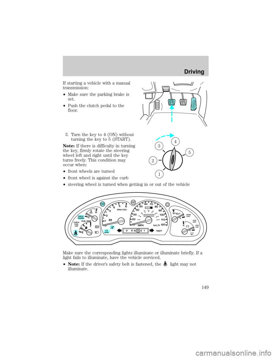
If starting a vehicle with a manual
transmission:
²Make sure the parking brake is
set.
²Push the clutch pedal to the
floor.
3. Turn the key to 4 (ON) without
turning the key to 5 (START).
Note:If there is difficulty in turning
the key, firmly rotate the steering
wheel left and right until the key
turns freely. This condition may
occur when:
²front wheels are turned
²front wheel is against the curb
²steering wheel is turned when getting in or out of the vehicle
Make sure the corresponding lights illuminate or illuminate briefly. If a
light fails to illuminate, have the vehicle serviced.
²Note:If the driver's safety belt is fastened, the
light may not
illuminate.
1
2
34
5
C
012345
6
RPMx1000
ABS!
BRAKE
CHECK
ENGINE
CHECK
FUEL
CAP
EFH
H
H
PRN D 2 1THEFT
SPEED
CONT
4WD
HIGH
4WD
LOW
O/D
OFFL
L
10MPH 205060
70
304080
90
km/h
0 0 0
10 100
1
20
1
0 0 0 0 0 0406080100
120
140
160
180
20
DOOR
AJAR
CHECK
GAGE
Driving
149
Page 164 of 287

4WD system indicator lights
The 4WD system indicator lights illuminate only under the following
conditions. If these lights illuminate when driving in 2WD, contact your
Mazda dealer as soon as possible.
²4WD-momentarily illuminates
when the vehicle is started.
Illuminates when 4H (4WD High)
is engaged.
²4WD LOW±momentarily
illuminates when the vehicle is
started. Illuminates when 4L
(4WD Low) is engaged.
Using the electronic shift 4WD system (if equipped)
Positions of the electronic shift system
2WD (2WD High)± Power to rear axle only.
4X4 HIGH (4WD High)± Power delivered to front and rear axles for
increased traction.
4X4 LOW (4WD Low)± Power to front and rear axles at low speeds.
Shifting from 2WD (2WD high) to 4X4 HIGH (4WD high)
Move the 4WD control to the 4X4
HIGH position.
²At temperatures below 0ÉC
(32ÉF), shifts from 2WD to 4X4
HIGH should not be performed
above 72 km/h (45 mph).
Do not shift into 4X4 HIGH with
the rear wheels slipping.
4WD
LOW
4X4
HIGH
2WD4X4
LOW
Driving
164