battery MAZDA MODEL B-SERIES 2002 Owners Manual (in English)
[x] Cancel search | Manufacturer: MAZDA, Model Year: 2002, Model line: MODEL B-SERIES, Model: MAZDA MODEL B-SERIES 2002Pages: 287, PDF Size: 2.47 MB
Page 3 of 287

Maintenance and Specifications 224
Hood 233
Engine compartment 234
Engine oil 238
Battery 244
Fuel information 251
Refill capacities 273
Lubricant specifications 276
Engine data 277
Vehicle dimensions 277
Accessories 280
Index 281
All rights reserved. Reproduction by any means, electronic or mechanical
including photocopying, recording or by any information storage and retrieval
system or translation in whole or part is not permitted without written
authorization from Mazda Motor Corporation. Mazda may change the contents
without notice and without incurring obligation.
Copyright 2001 Mazda Motor Corporation
Table of Contents
3
Page 9 of 287

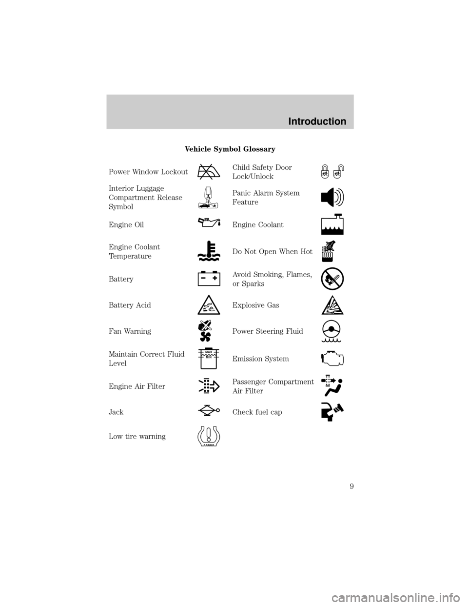
Vehicle Symbol Glossary
Power Window Lockout
Child Safety Door
Lock/Unlock
Interior Luggage
Compartment Release
SymbolPanic Alarm System
Feature
Engine OilEngine Coolant
Engine Coolant
TemperatureDo Not Open When Hot
BatteryAvoid Smoking, Flames,
or Sparks
Battery AcidExplosive Gas
Fan WarningPower Steering Fluid
Maintain Correct Fluid
LevelMAX
MIN
Emission System
Engine Air FilterPassenger Compartment
Air Filter
JackCheck fuel cap
Low tire warning
Introduction
9
Page 17 of 287

Charging system
Illuminates when the battery is not
charging properly.
Check fuel cap
Illuminates when the fuel cap is not
installed correctly. Check the fuel
cap for proper installation. When
the fuel filler cap is properly
re-installed, the light(s) will turn off
after a period of normal driving. Continuing to operate the vehicle with
the check fuel cap light on, can activate theCheck Enginewarning light.
It may take a long period of time for the system to detect an
improperly installed fuel filler cap.
For more information, refer toFuel filler capin theMaintenance and
specificationschapter.
Speed control
Illuminates when the speed control
is activated.
O/D off
Illuminates when the overdrive
function has been turned OFF using
the transmission control switch
(TCS).
If the light does not come on or the light flashes steadily, have
your vehicle serviced as soon as possible, damage to the
transmission could occur.
CHECK
FUEL
CAP
SPEED
CONT
O/D
OFF
Instrument Cluster
17
Page 21 of 287

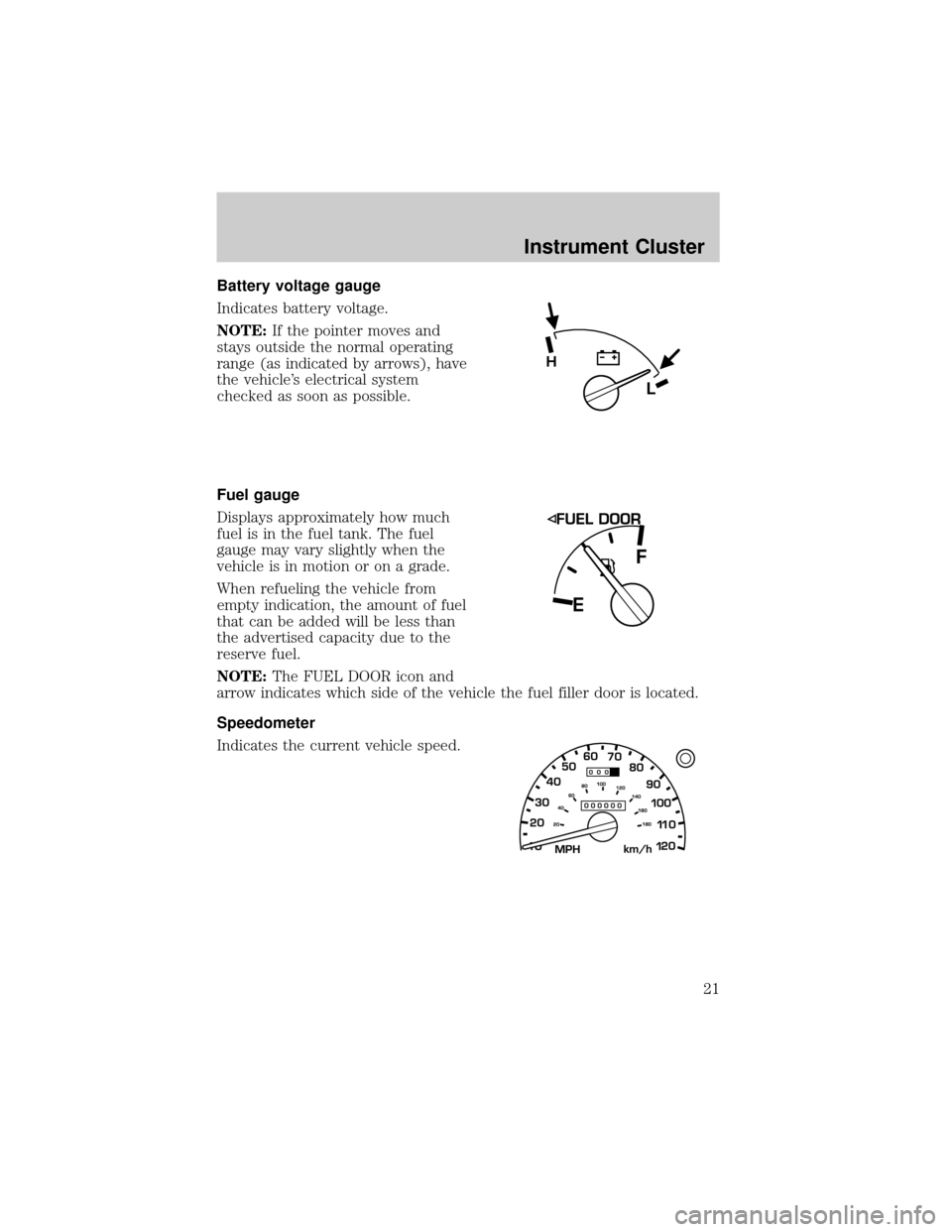
Battery voltage gauge
Indicates battery voltage.
NOTE:If the pointer moves and
stays outside the normal operating
range (as indicated by arrows), have
the vehicle's electrical system
checked as soon as possible.
Fuel gauge
Displays approximately how much
fuel is in the fuel tank. The fuel
gauge may vary slightly when the
vehicle is in motion or on a grade.
When refueling the vehicle from
empty indication, the amount of fuel
that can be added will be less than
the advertised capacity due to the
reserve fuel.
NOTE:The FUEL DOOR icon and
arrow indicates which side of the vehicle the fuel filler door is located.
Speedometer
Indicates the current vehicle speed.
L
H
Instrument Cluster
21
Page 103 of 287

Unlocking the doors
Press this control to unlock the
driver's door. The interior lamps will
illuminate.
Press the control a second time
within five seconds to unlock all
doors.
Locking the doors
Press this control to lock all doors.
To confirm all doors are closed and
locked, press the control a second
time within five seconds. The doors
will lock again, the horn will chirp
and the lamps will flash.
If any of the doors are ajar, the horn
will make two quick chirps,
reminding you to properly close all
doors.
Illuminated entry
The interior lamps illuminate when the remote entry system is used to
unlock the door(s) or sound the personal alarm.
The system automatically turns off after 25 seconds or when the ignition
is turned to the ON or ACC position.
NOTE:The dome lamp control (if equipped) mustnotbe set to the
OFF position for the illuminated entry system to operate.
The inside lights will not turn off if:
²they have been turned on with the dimmer control or
²any door is open
NOTE:The battery saver will shut off the interior lamps 45 minutes
after the ignition has been turned to the OFF position.
Locks and Security
103
Page 105 of 287

Replacing the battery
The transmitter is powered by one coin type three-volt lithium battery
CR2032 or equivalent. Typical operating range will allow you to be up to
10 meters (33 feet) away from your vehicle. A decrease in operating
range can be caused by:
²weather conditions
²nearby radio towers
²structures around the vehicle
²other vehicles parked next to the vehicle
To replace the battery:
1. Twist a thin coin between the
two halves of the transmitter
near the key ring.
DO NOT TAKE THE FRONT
PART OF THE TRANSMITTER
APART. Damage to the
transmitter may result in
operation failure.
2.
Place the positive (+) side of
new battery in the same
orientation. Refer to the diagram
inside the transmitter unit.
3. Snap the two halves back
together.
Replacing lost transmitters
If a remote transmitter has been lost
and you would like to remove it
from the vehicle's memory, or you
would like to purchase additional
remote transmitters and have them
programmed to your vehicle:
²Takeallyour vehicle's
transmitters to your dealer for
programming, or
²Perform the programming
procedure yourself
Locks and Security
105
Page 158 of 287

WARNING: If the parking brake is fully released, but the brake
warning lamp remains illuminated, the brakes may not be
working properly. See your authorized Mazda dealership.
Driving with a 5±speed automatic transmission (if equipped)
Your automatic transmission electronically controls the shift feel by using
an adaptive learning strategy. This feature is designed to increase
durability, and provide consistent shift feel over the life of the vehicle. It
is normal for a new transmission to shift firmly. This operation is
considered normal and will not affect function or durability of the
transmission. Once the vehicle is at operating temperature it may take
several shifts at the same operating condition for the transmission to
properly adapt. Over time the adaptive learning process will fully update
transmission operation. The more varied the driving habits, speed and
torque, the longer it may take to adapt, but the more complete the
process will be.
When the battery is disconnected or a new battery installed, the
transmission must learn its adaptive strategy. As a result of this, the
transmission may shift firmly. This operation is considered normal and
will fully update transmission operation to its optimum shift feel.
Understanding gearshift positions
WARNING: Hold the brake pedal down while you move the
gearshift lever from P (Park) to another position. If you do not
hold the brake pedal down, your vehicle may move unexpectedly
and injure someone.
P (Park)
To put your vehicle in gear, start the engine, depress the brake pedal,
then move gearshift lever out of P (Park).
Driving
158
Page 177 of 287

Refer to the following chart for information regarding the
factory-equipped trailer tow connector:
Trailer tow connector
Color Function Comment
1. Dark Green Trailer right-hand
turn signalCircuit activated when brake
pedal is depressed or when
ignition is on and right-hand
turn signal is applied.
2. Yellow Trailer left-hand turn
signalCircuit activated when brake
pedal is depressed or when
ignition is on and left-hand
turn signal is applied.
3. Tan/White Tail lamp Relay controlled circuit
activated when the park
lamps/headlamps are on.
4. White Ground Matching vehicle circuit
returns to battery's negative
ground.
Driving while you tow
When towing a trailer:
²Ensure that you turn off your speed control. The speed control may
shut off automatically when you are towing on long, steep grades.
²Consult your local motor vehicle speed regulations for towing a trailer.
²Use a lower gear when towing up or down steep hills. This will
eliminate excessive downshifting and upshifting for optimum fuel
economy and transmission cooling.
²Anticipate stops and brake gradually.
Exceeding the GCWR rating may cause internal transmission
damage and void your warranty coverage.
Servicing after towing
If you tow a trailer for long distances, your vehicle will require more
frequent service intervals. Refer to your service maintenance section for
more information.
Driving
177
Page 187 of 287

Fuse/Relay
LocationFuse Amp
RatingPassenger Compartment Fuse
Panel Description
26 10A Battery Saver Relay, Auxillary
Relay Box, Restraint Central
Module (RCM), Generic Electroic
Module (GEM), Instrument
Cluster
27 Ð Not Used
28 7.5A Generic Electronic Module
(GEM), Radio
29 20A Radio
30 Ð Not Used
31 Ð Not Used
32 Ð Not Used
33 15A Headlamps, Daytime Running
Lamps (DRL) Module, Instrument
Cluster
34 Ð Not Used
35 15A Horn Relay (If Not Equipped with
Central Security Module)
36 Ð Not Used
Power distribution box
The power distribution box is
located in the engine compartment.
The power distribution box contains
high-current fuses that protect your
vehicle's main electrical systems
from overloads.
WARNING: Always disconnect the battery before servicing high
current fuses.
Roadside Emergencies
187
Page 188 of 287

WARNING: To reduce risk of electrical shock, always replace
the cover to the Power Distribution Box before reconnecting
the battery or refilling fluid reservoirs.
If the battery has been disconnected and reconnected, refer to the
Batterysection of theMaintenance and specificationschapter.
2.3L engine (if equipped)
The high-current fuses are coded as follows:
Fuse/Relay
LocationFuse Amp
RatingPower Distribution Box
Description
1 50A** I/P Fuse Panel
2 Ð Not Used
3 Ð Not Used
4 Ð Not Used
5 Ð Not Used
6 50A** ABS Pump Motor
7 30A* Powertrain Control Module (PCM)
1234521 22 23 24
25 26 27 28
29 30 31 32
33 34 35 36
37 38 39 40
41 42 43 44
67891055
49 4854 53 52
515656 B
56 A
5050 B
50 A 47 4545 B
45 A
4646 B
46 A 11 12 13 14 15
16 17 18 19 20
Roadside Emergencies
188