ECU MAZDA MODEL B-SERIES 2003 Owners Manual (in English)
[x] Cancel search | Manufacturer: MAZDA, Model Year: 2003, Model line: MODEL B-SERIES, Model: MAZDA MODEL B-SERIES 2003Pages: 245, PDF Size: 2.33 MB
Page 1 of 245

Introduction 4
Instrument Cluster 12
Warning and control lights 12
Gauges 16
Entertainment Systems 19
AM/FM stereo 19
AM/FM stereo with CD 21
AM/FM stereo with in-dash six CD 23
AM/FM stereo with CD/MP3 27
Climate Controls 35
Manual heating and air conditioning 35
Lights 38
Headlamps 38
Turn signal control 40
Bulb replacement 40
Driver Controls 47
Windshield wiper/washer control 47
Power windows 49
Speed control (Cruise control) 53
Locks and Security 59
Keys 59
Locks 59
Anti-theft system 59
Table of Contents
1
Page 12 of 245

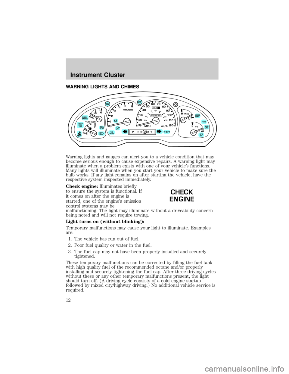
WARNING LIGHTS AND CHIMES
Warning lights and gauges can alert you to a vehicle condition that may
become serious enough to cause expensive repairs. A warning light may
illuminate when a problem exists with one of your vehicle's functions.
Many lights will illuminate when you start your vehicle to make sure the
bulb works. If any light remains on after starting the vehicle, have the
respective system inspected immediately.
Check engine:Illuminates briefly
to ensure the system is functional. If
it comes on after the engine is
started, one of the engine's emission
control systems may be
malfunctioning. The light may illuminate without a driveability concern
being noted and will not require towing.
Light turns on (without blinking):
Temporary malfunctions may cause your light to illuminate. Examples
are:
1. The vehicle has run out of fuel.
2. Poor fuel quality or water in the fuel.
3. The fuel cap may not have been properly installed and securely
tightened.
These temporary malfunctions can be corrected by filling the fuel tank
with high quality fuel of the recommended octane and/or properly
installing and securely tightening the fuel cap. After three driving cycles
without these or any other temporary malfunctions present, the light
should turn off. (A driving cycle consists of a cold engine startup
followed by mixed city/highway driving.) No additional vehicle service is
required.
CHECK
ENGINE
Instrument Cluster
12
Page 15 of 245

Door ajar:Illuminates when the
ignition is in the ON position and
any door is open.
Overdrive off (if equipped):
Illuminates when the overdrive
function has been turned OFF using
the transmission control switch
(TCS).
If the light does not come on or the light flashes steadily, have
your vehicle serviced as soon as possible, damage to the
transmission could occur.
Four wheel drive low (if
equipped):Illuminates when
four-wheel drive low is engaged.
NOTE:If the light continues to
flash have the system serviced.
Four wheel drive high (if
equipped):Illuminates when
four-wheel drive high is engaged.
NOTE:If the light continues to
flash have the system serviced.
Anti-theft system:Flashes when
the SecurilockyPassive Anti-theft
System has been activated.
Speed control:Illuminates when
the speed control is engaged. Turns
off when the speed control system
is disengaged.
Turn signal:Illuminates when the
left or right turn signal or the
hazard lights are turned on. If the
indicators stay on or flash faster, check for a burned out bulb.
High beams:Illuminates when the
high beam headlamps are turned on.
DOOR
AJAR
O/D
OFF
4WD
LOW
SPEED
CONT
Instrument Cluster
15
Page 43 of 245

To install the new bulb:
Handle a halogen headlamp bulb carefully and keep out of
children's reach. Grasp the bulb only by its plastic base and do
not touch the glass. The oil from your hands could cause the bulb
to break the next time the headlamps are operated. Always wear
safety glasses while handling bulbs.
NOTE: If the bulb is accidentally touched, it should be cleaned with
rubbing alcohol before being used.
1. With the flat side of the bulb's plastic base facing upward, insert the
glass end of the bulb into the lamp assembly. You may need to turn
the bulb left or right to align the grooves in the plastic base with the
tabs in the lamp assembly. When the grooves are aligned, push the
bulb into the lamp assembly until the plastic base contacts the rear
of the lamp assembly.
2. Install the bulb retaining ring over the plastic base until it contacts
the rear of the socket by rotating clockwise until you feel a ªstop.º
3. Install the electrical connector into the plastic base until it snaps,
locking it into position.
4. Install the headlamp on vehicle, push rearward and secure with two
retainer pins.
5. Turn the headlamps on and make sure they work properly. If the
headlamp was correctly aligned before you changed the bulb, you
should not need to align it again.
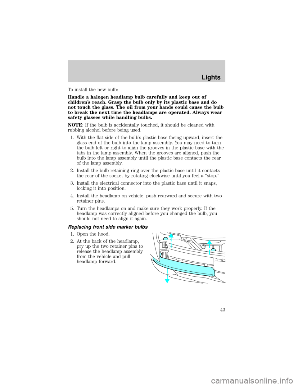
Replacing front side marker bulbs
1. Open the hood.
2. At the back of the headlamp,
pry up the two retainer pins to
release the headlamp assembly
from the vehicle and pull
headlamp forward.
Lights
43
Page 44 of 245

3. Remove screw(s) from lamp
assembly.
4. Disengage lamp assembly (it has
a snap fit).
5. Rotate bulb socket
counterclockwise and remove
from lamp assembly.
6. Carefully pull bulb straight out
of socket and push in the new
bulb.
7. Install the bulb socket in lamp
assembly by turning clockwise.
8. Align the lamp on the vehicle
and push to snap in place.
9. Install screw(s) on lamp assembly.
10. Install the headlamp on vehicle, push rearward and secure with two
retainer pins.
Lights
44
Page 45 of 245

Replacing tail lamp/backup lamp bulbs
The tail lamp/backup lamp bulbs are
located in the same portion of the
tail lamp assembly, one just below
the other. Follow the same steps to
replace either bulb:
1. Open the tailgate to expose the
lamp assemblies.
2. Remove the four screws and the
lamp assembly from vehicle.
3. Rotate bulb socket
counterclockwise turn and
remove from lamp assembly.
4. Carefully pull the bulb straight
out of the socket and push in
the new bulb.
5. Install the bulb socket in lamp
assembly by turning clockwise.
6. Install the lamp assembly and
secure with four screws.
Replacing fog lamp bulbs
1. Remove the bulb socket from
the fog lamp by turning
counterclockwise.
2. Disconnect the electrical
connector from the fog lamp
bulb.
3. Connect the electrical connector to the new fog lamp bulb.
4. Install the bulb socket in the fog lamp turning clockwise.
Lights
45
Page 46 of 245

Replacing high-mount brake lamp and cargo lamp bulbs
The replacement of the high-mount brake lamp bulb and cargo lamp bulb
is basically the same. This procedure covers the high-mount brake lamp
bulb.
To remove the brake lamp assembly:
1. Remove the two screws and
lamp assembly from vehicle.
2. Remove the bulb socket from
lamp assembly by rotating it
counterclockwise.
3. Carefully pull bulb straight out
of socket and push in the new
bulb.
To install the brake lamp assembly:
1. Install the bulb socket into the
lamp assembly by rotating
clockwise.
2. Install the lamp assembly on the vehicle and secure with two screws.
Replacing license plate lamp bulbs
The license plate bulbs are located
behind the rear bumper. To change
the license plate lamp bulbs:
1. Reach behind the rear bumper
to locate the bulb socket.
2. Twist the socket
counterclockwise and remove.
3. Pull out the old bulb from
socket and push in the new
bulb.
4. Install the bulb socket in lamp assembly by turning it clockwise.
Lights
46
Page 57 of 245

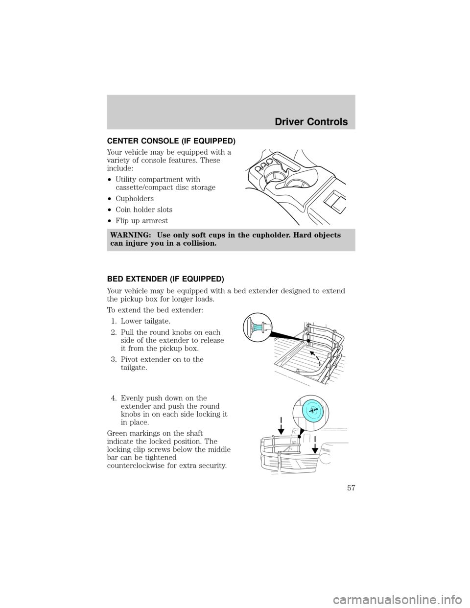
CENTER CONSOLE (IF EQUIPPED)
Your vehicle may be equipped with a
variety of console features. These
include:
²Utility compartment with
cassette/compact disc storage
²Cupholders
²Coin holder slots
²Flip up armrest
WARNING: Use only soft cups in the cupholder. Hard objects
can injure you in a collision.
BED EXTENDER (IF EQUIPPED)
Your vehicle may be equipped with a bed extender designed to extend
the pickup box for longer loads.
To extend the bed extender:
1. Lower tailgate.
2. Pull the round knobs on each
side of the extender to release
it from the pickup box.
3. Pivot extender on to the
tailgate.
4. Evenly push down on the
extender and push the round
knobs in on each side locking it
in place.
Green markings on the shaft
indicate the locked position. The
locking clip screws below the middle
bar can be tightened
counterclockwise for extra security.
Driver Controls
57
Page 58 of 245

Note: If the red marking on the shaft is visible, the bed extender
is not locked or properly secured.
To stow the bed extender, follow steps one through four in reverse order.
The bed extender may be used to secure a load of up to 46 kg (100 lbs.)
on the tailgate.
The bed extender should always be kept in the stowed position
with the tailgate closed when not in use.
To remove the bed extender:
1. Extend the bed extender.
2. Pull the round knobs on each
side of the extender to unlock
it.
Make sure the locking clip screws
are loose before removing the
extender.
1. Press the locking clips below
the middle bar on each side and
lift the extender out of the bed.
To install the bed extender, follow the removal procedure in reverse
order.
Driver Controls
58
Page 59 of 245

KEYS
The key operates all locks on your vehicle. In case of loss, replacement
keys are available from your dealer.
You should always carry a second key with you in a safe place in case
you require it in an emergency.
Refer toSecuriLockyPassive Anti-Theft Systemfor more information.
POWER DOOR LOCKS (IF EQUIPPED)
Press the top of the control to
unlock all doors and the bottom to
lock all doors.
REMOTE ENTRY SYSTEM (IF EQUIPPED)
The remote entry system allows you to lock or unlock all vehicle doors
without a key.
The remote entry features only operate with the ignition in the LOCK
position.
If there is any potential remote keyless entry problem with your vehicle,
ensureALL remote entry transmittersare brought to the dealership,
to aid in troubleshooting.
GENERAL INFORMATION: This device complies with part 15 of the FCC
rules and with RS-210 of Industry Canada. Operation is subject to the
following two conditions: (1) This device may not cause harmful
interference, and (2) This device must accept any interference received,
including interference that may cause undesired operation. Changes or
modifications not expressly approved by the party responsible for
compliance could void the user's authority to operate the equipment.
This device complies with part 15 of the FCC rules and with RS-210 of
Industry Canada. Operation is subject to the following two conditions:
(1) This device may not cause harmful interference, and (2) This device
must accept any interference received, including interference that may
cause undesired operation.
UNLOCK
LOCK
Locks and Security
59