tow MAZDA MODEL B-SERIES 2003 Owners Manual (in English)
[x] Cancel search | Manufacturer: MAZDA, Model Year: 2003, Model line: MODEL B-SERIES, Model: MAZDA MODEL B-SERIES 2003Pages: 245, PDF Size: 2.33 MB
Page 2 of 245
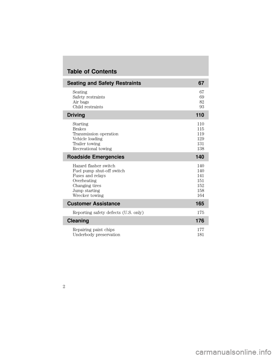
Seating and Safety Restraints 67
Seating 67
Safety restraints 69
Air bags 82
Child restraints 93
Driving 110
Starting 110
Brakes 115
Transmission operation 119
Vehicle loading 129
Trailer towing 131
Recreational towing 138
Roadside Emergencies 140
Hazard flasher switch 140
Fuel pump shut-off switch 140
Fuses and relays 141
Overheating 151
Changing tires 152
Jump starting 158
Wrecker towing 164
Customer Assistance 165
Reporting safety defects (U.S. only) 175
Cleaning 176
Repairing paint chips 177
Underbody preservation 181
Table of Contents
2
Page 5 of 245
SAFETY AND ENVIRONMENT PROTECTION
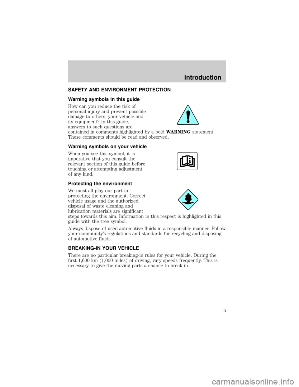
Warning symbols in this guide
How can you reduce the risk of
personal injury and prevent possible
damage to others, your vehicle and
its equipment? In this guide,
answers to such questions are
contained in comments highlighted by a boldWARNINGstatement.
These comments should be read and observed.
Warning symbols on your vehicle
When you see this symbol, it is
imperative that you consult the
relevant section of this guide before
touching or attempting adjustment
of any kind.
Protecting the environment
We must all play our part in
protecting the environment. Correct
vehicle usage and the authorized
disposal of waste cleaning and
lubrication materials are significant
steps towards this aim. Information in this respect is highlighted in this
guide with the tree symbol.
Always dispose of used automotive fluids in a responsible manner. Follow
your community's regulations and standards for recycling and disposing
of automotive fluids.
BREAKING-IN YOUR VEHICLE
There are no particular breaking-in rules for your vehicle. During the
first 1,600 km (1,000 miles) of driving, vary speeds frequently. This is
necessary to give the moving parts a chance to break in.
Introduction
5
Page 12 of 245
WARNING LIGHTS AND CHIMES
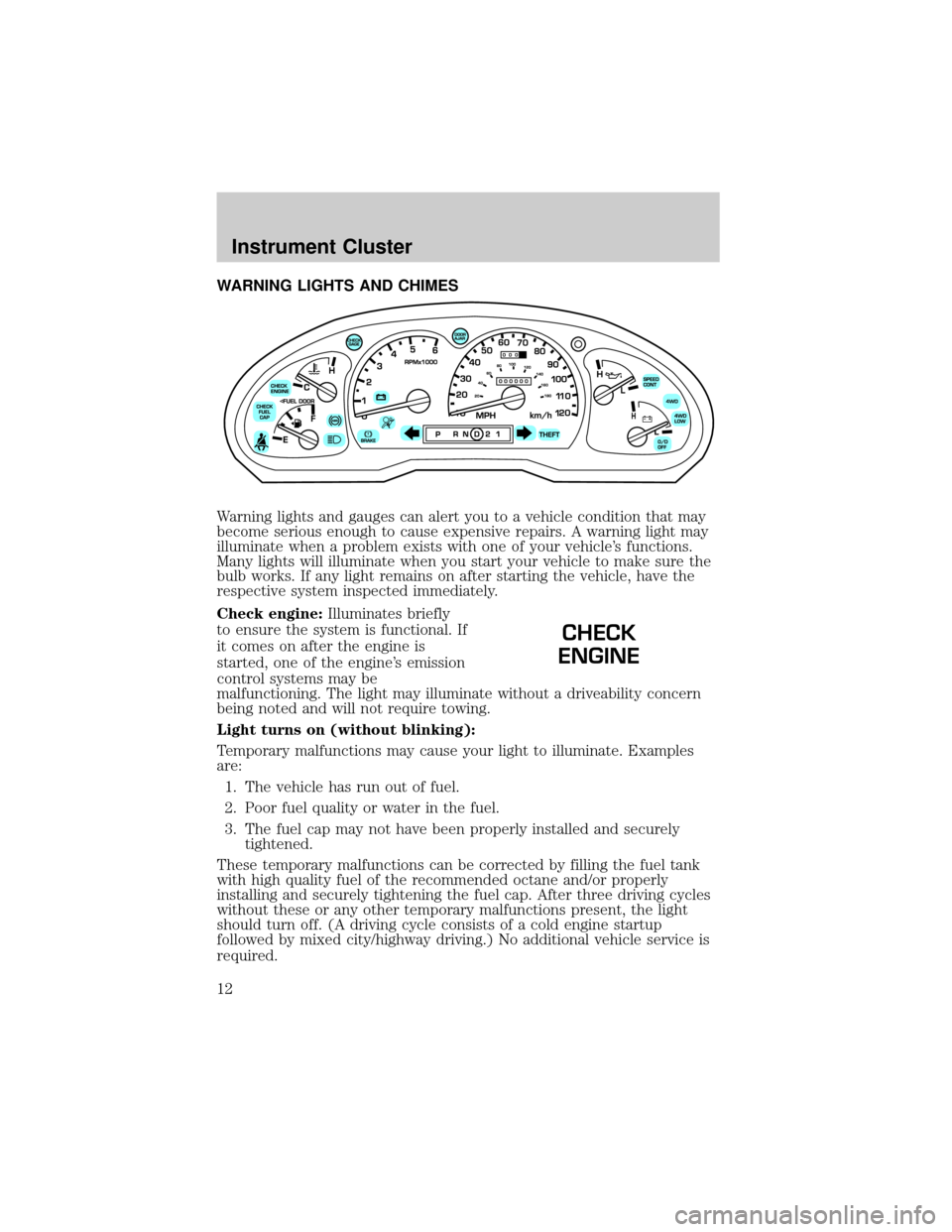
Warning lights and gauges can alert you to a vehicle condition that may
become serious enough to cause expensive repairs. A warning light may
illuminate when a problem exists with one of your vehicle's functions.
Many lights will illuminate when you start your vehicle to make sure the
bulb works. If any light remains on after starting the vehicle, have the
respective system inspected immediately.
Check engine:Illuminates briefly
to ensure the system is functional. If
it comes on after the engine is
started, one of the engine's emission
control systems may be
malfunctioning. The light may illuminate without a driveability concern
being noted and will not require towing.
Light turns on (without blinking):
Temporary malfunctions may cause your light to illuminate. Examples
are:
1. The vehicle has run out of fuel.
2. Poor fuel quality or water in the fuel.
3. The fuel cap may not have been properly installed and securely
tightened.
These temporary malfunctions can be corrected by filling the fuel tank
with high quality fuel of the recommended octane and/or properly
installing and securely tightening the fuel cap. After three driving cycles
without these or any other temporary malfunctions present, the light
should turn off. (A driving cycle consists of a cold engine startup
followed by mixed city/highway driving.) No additional vehicle service is
required.
CHECK
ENGINE
Instrument Cluster
12
Page 33 of 245

RADIO FREQUENCIES
AM and FM frequencies are established by the Federal Communications
Commission (FCC) and the Canadian Radio and Telecommunications
Commission (CRTC). Those frequencies are:
AM - 530, 540±1600, 1610 kHz
FM- 87.7, 87.9±107.7, 107.9 MHz
RADIO RECEPTION FACTORS
There are three factors that can effect radio reception:
²Distance/strength: The further you travel from an FM station, the
weaker the signal and the weaker the reception.
²Terrain: Hills, mountains, tall buildings, power lines, electric fences,
traffic lights and thunderstorms can interfere with your reception.
²Station overload: When you pass a broadcast tower, a stronger signal
may overtake a weaker one and play while the weak station frequency
is displayed.
CASSETTE/PLAYER CARE
Do:
²Use only cassettes which are 90 minutes long or less.
²Tighten very loose tapes by inserting a finger or pencil into the hole
and turning the hub.
²Remove loose labels before inserting tapes.
²Allow tapes which have been subjected to extreme heat, humidity or
cold to reach a moderate temperature before playing.
²Clean the cassette player head with a cassette cleaning cartridge after
10±12 hours of play to maintain good sound/operation.
Don't:
²Expose tapes to direct sunlight, extreme humidity, heat or cold.
²Leave tapes in the cassette player for a long time when not being
played.
CD/CD PLAYER CARE
Do:
²Handle discs by their edges only. Never touch the playing surface.
²Inspect discs before playing. Clean only with an approved CD cleaner
and wipe from the center out.
Entertainment Systems
33
Page 36 of 245
4. Direct the outer instrument panel vents towards the side windows
To increase airflow to the outer instrument panel vents, close the vents
located in the middle of the instrument panel.
WARNING: Do not place objects on top of the instrument panel
as these objects may become projectiles in a collision or sudden
stop.
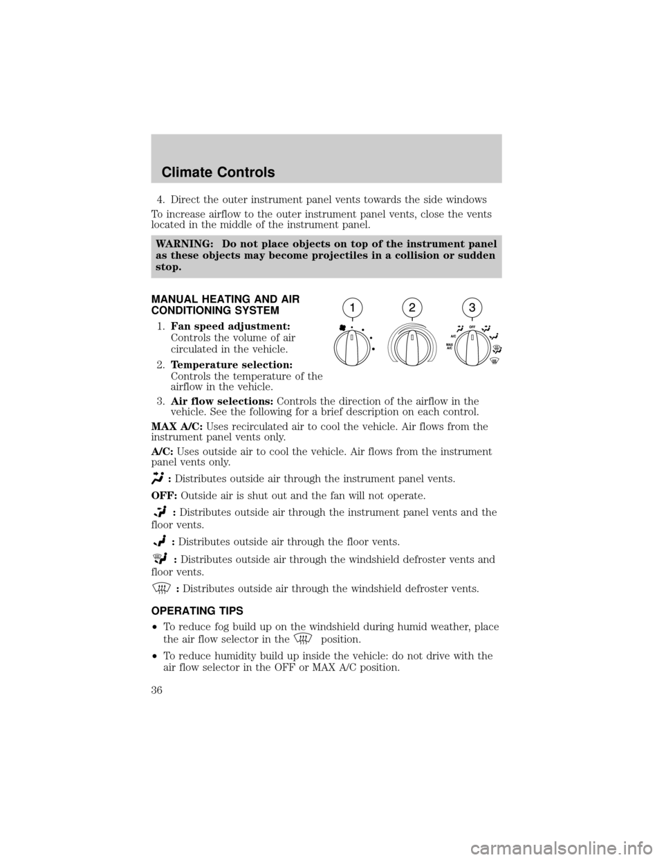
MANUAL HEATING AND AIR
CONDITIONING SYSTEM
1.Fan speed adjustment:
Controls the volume of air
circulated in the vehicle.
2.Temperature selection:
Controls the temperature of the
airflow in the vehicle.
3.Air flow selections:Controls the direction of the airflow in the
vehicle. See the following for a brief description on each control.
MAX A/C:Uses recirculated air to cool the vehicle. Air flows from the
instrument panel vents only.
A/C:Uses outside air to cool the vehicle. Air flows from the instrument
panel vents only.
:Distributes outside air through the instrument panel vents.
OFF:Outside air is shut out and the fan will not operate.
:Distributes outside air through the instrument panel vents and the
floor vents.
:Distributes outside air through the floor vents.
:Distributes outside air through the windshield defroster vents and
floor vents.
:Distributes outside air through the windshield defroster vents.
OPERATING TIPS
²To reduce fog build up on the windshield during humid weather, place
the air flow selector in the
position.
²To reduce humidity build up inside the vehicle: do not drive with the
air flow selector in the OFF or MAX A/C position.
Climate Controls
36
Page 37 of 245
²Under normal weather conditions, do not leave the air flow selector in
MAX A/C or OFF when the vehicle is parked. This allows the vehicle
to ªbreatheº using the outside air inlet vents.
²Do not put objects under the front seats that will interfere with the
airflow to the back seats.
²Remove any snow, ice or leaves from the air intake area at the base of
the windshield.
To aid in side window defogging/demisting in cold weather:
1. Select
2. Select A/C
3. Modulate the temperature control to maintain comfort.
4. Set the fan speed to HI
5. Direct the outer instrument panel vents towards the side windows
To increase airflow to the outer instrument panel vents, close the vents
located in the middle of the instrument panel.
WARNING: Do not place objects on top of the instrument panel
as these objects may become projectiles in a collision or sudden
stop.
Climate Controls
37
Page 39 of 245
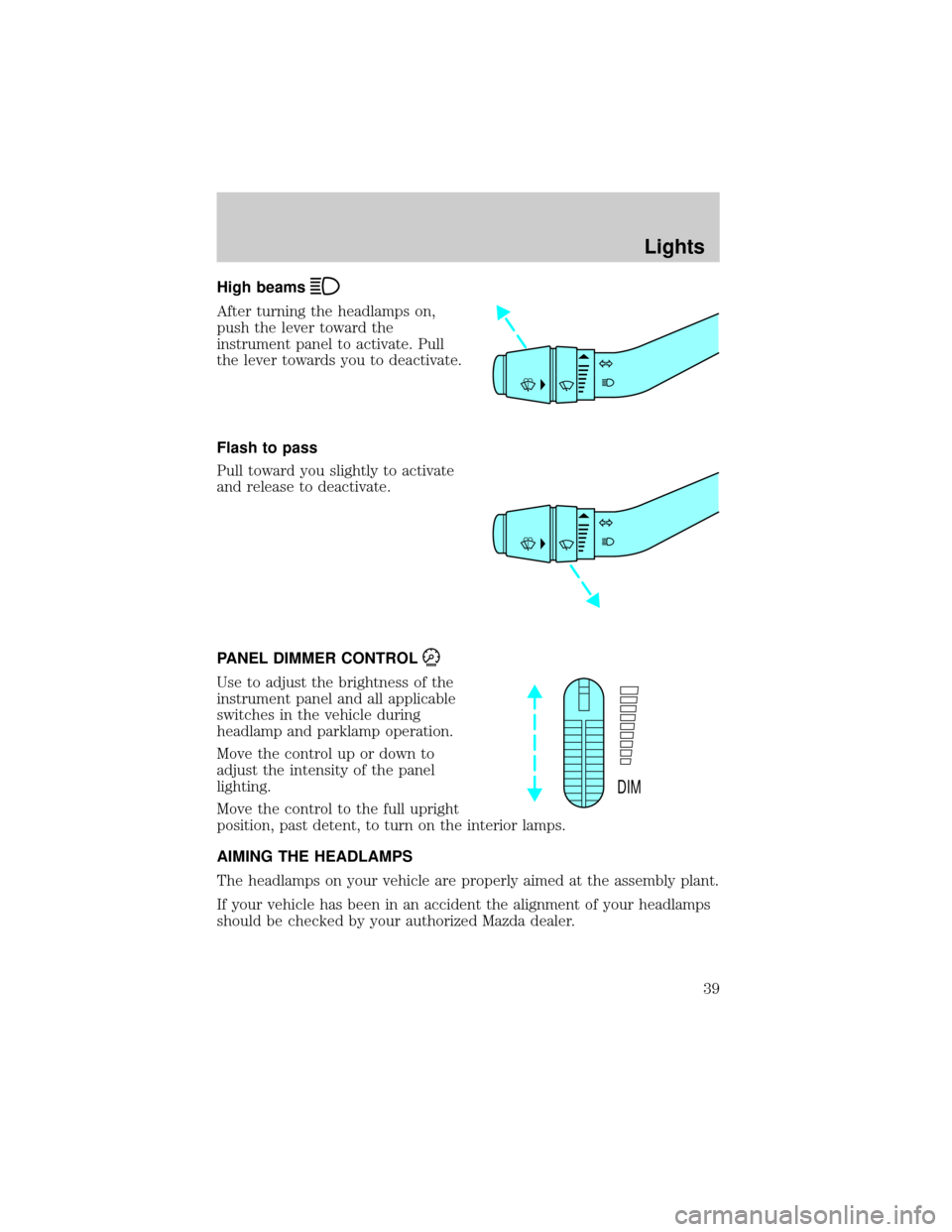
High beams
After turning the headlamps on,
push the lever toward the
instrument panel to activate. Pull
the lever towards you to deactivate.
Flash to pass
Pull toward you slightly to activate
and release to deactivate.
PANEL DIMMER CONTROL
Use to adjust the brightness of the
instrument panel and all applicable
switches in the vehicle during
headlamp and parklamp operation.
Move the control up or down to
adjust the intensity of the panel
lighting.
Move the control to the full upright
position, past detent, to turn on the interior lamps.
AIMING THE HEADLAMPS
The headlamps on your vehicle are properly aimed at the assembly plant.
If your vehicle has been in an accident the alignment of your headlamps
should be checked by your authorized Mazda dealer.
DIM
Lights
39
Page 47 of 245

MULTI-FUNCTION LEVER
Windshield wiper:Rotate the end
of the control away from you to
increase the speed of the wipers;
rotate towards you to decrease the
speed of the wipers.
Windshield washer:Push the end
of the stalk:
²briefly: causes a single swipe of
the wipers without washer fluid.
²a quick push and hold: the wipers
will swipe three times with
washer fluid.
²a long push and hold: the wipers and washer fluid will be activated for
up to ten seconds.
Windshield wiper blades
If the wiper blades do not wipe properly, clean both the windshield and
wiper blades using undiluted windshield wiper solution or a mild
detergent. Rinse thoroughly with clean water. To avoid damaging the
blades, do not use fuel, kerosene, paint thinner or other solvents.
Check the wiper blades for wear at least twice a year or when they seem
less effective. Substances such as tree sap and some hot wax treatments
used by commercial car washes reduce the effectiveness of wiper blades.
Note:There are different wiper blades for cold and warm weather use.
Driver Controls
47
Page 48 of 245

Changing the wiper blades
1. Pull the wiper arm away from
the vehicle. Turn the blade at an
angle from the wiper arm. Push
the lock pin manually to release
the blade and pull the wiper
blade down toward the
windshield to remove it from
the arm.
2. Attach the new wiper to the
wiper arm and press it into
place until a click is heard.
3. Replace wiper blades every 6 months for optimum performance.
TILT STEERING WHEEL (IF EQUIPPED)
To adjust the steering wheel:
1. Pull and hold the steering wheel
release control toward you.
2. Move the steering wheel up or
down until you find the desired
location.
3. Release the steering wheel
release control. This will lock
the steering wheel in position.
WARNING: Never adjust the steering wheel when the vehicle is
moving.
Driver Controls
48
Page 58 of 245

Note: If the red marking on the shaft is visible, the bed extender
is not locked or properly secured.
To stow the bed extender, follow steps one through four in reverse order.
The bed extender may be used to secure a load of up to 46 kg (100 lbs.)
on the tailgate.
The bed extender should always be kept in the stowed position
with the tailgate closed when not in use.
To remove the bed extender:
1. Extend the bed extender.
2. Pull the round knobs on each
side of the extender to unlock
it.
Make sure the locking clip screws
are loose before removing the
extender.
1. Press the locking clips below
the middle bar on each side and
lift the extender out of the bed.
To install the bed extender, follow the removal procedure in reverse
order.
Driver Controls
58