relay MAZDA MODEL B2300 2003 Owners Manual (in English)
[x] Cancel search | Manufacturer: MAZDA, Model Year: 2003, Model line: MODEL B2300, Model: MAZDA MODEL B2300 2003Pages: 248, PDF Size: 2.71 MB
Page 2 of 248

Seating and Safety Restraints 67
Seating 67
Safety restraints 69
Air bags 82
Child restraints 93
Driving 110
Starting 110
Brakes 115
Transmission operation 119
Vehicle loading 129
Trailer towing 131
Recreational towing 138
Roadside Emergencies 140
Hazard flasher switch 140
Fuel pump shut-off switch 140
Fuses and relays 141
Overheating 151
Changing tires 152
Jump starting 158
Wrecker towing 164
Customer Assistance 165
Reporting safety defects (U.S. only) 175
Cleaning 176
Repairing paint chips 177
Underbody preservation 181
Table of Contents
2
Page 119 of 248

WARNING: Loaded vehicles, with a higher center of gravity,
may handle differently than unloaded vehicles. Extra
precautions, such as slower speeds and increased stopping
distance, should be taken when driving a heavily loaded vehicle.
AUTOMATIC TRANSMISSION OPERATION (IF EQUIPPED)
Brake-shift interlock
This vehicle is equipped with a brake-shift interlock feature that prevents
the gearshift lever from being moved from P (Park) when the ignition is
in the ON position unless the brake pedal is depressed.
If you cannot move the gearshift lever out of P (Park) with ignition in
the ON position and the brake pedal depressed:
1. Apply the parking brake, turn
ignition key to LOCK, then
remove the key.
2. Insert the key and turn it to
OFF.Apply the brake pedal
and shift to N (Neutral).
WARNING: In the ignition OFF position, the automatic
transmission shift lever can be moved from the P (Park)
position without the brake pedal depressed. To avoid unwanted
vehicle movement, always set the parking brake.
3. Start the vehicle.
If it is necessary to use the above procedure to move the gearshift lever,
it is possible that a fuse has blown or the vehicle's brakelamps are not
operating properly. Refer toFuses and relaysin theRoadside
emergencieschapter.
WARNING: Do not drive your vehicle until you verify that the
brakelamps are working.
Driving
119
Page 137 of 248

Trailer tow connector
Color Function Comment
3. Tan/White Tail lamp Relay controlled circuit
activated when the park
lamps/headlamps are on.
4. White Ground Matching vehicle circuit
returns to battery's negative
ground.
Driving while you tow
When towing a trailer:
²Turn off the speed control. The speed control may shut off
automatically when you are towing on long, steep grades.
²Consult your local motor vehicle speed regulations for towing a trailer.
²To eliminate excessive shifting, use a lower gear. This will also assist
in transmission cooling. (For additional information, refer to the
Driving with a 5±speed automatic transmissionsection in this
chapter.
²Anticipate stops and brake gradually.
²Do not exceed the GCWR rating or transmission damage may occur.
Servicing after towing
If you tow a trailer for long distances, your vehicle will require more
frequent service intervals. Refer to your service maintenance section for
more information.
Trailer towing tips
²Practice turning, stopping and backing up before starting on a trip to
get the feel of the vehicle trailer combination. When turning, make
wider turns so the trailer wheels will clear curbs and other obstacles.
²Allow more distance for stopping with a trailer attached.
²The trailer tongue weight should be 10±15% of the loaded trailer
weight.
²After you have traveled 80 km (50 miles), thoroughly check your
hitch, electrical connections and trailer wheel lug nuts.
²To aid in engine/transmission cooling and A/C efficiency during hot
weather while stopped in traffic, place the gearshift lever in P (Park)
(automatic transmission) or N (Neutral) (manual transmissions).
Driving
137
Page 141 of 248

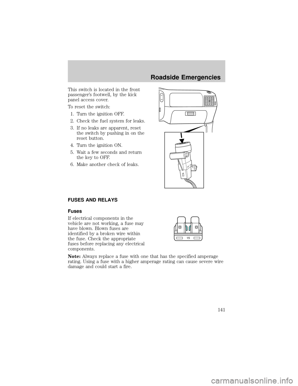
This switch is located in the front
passenger's footwell, by the kick
panel access cover.
To reset the switch:
1. Turn the ignition OFF.
2. Check the fuel system for leaks.
3. If no leaks are apparent, reset
the switch by pushing in on the
reset button.
4. Turn the ignition ON.
5. Wait a few seconds and return
the key to OFF.
6. Make another check of leaks.
FUSES AND RELAYS
Fuses
If electrical components in the
vehicle are not working, a fuse may
have blown. Blown fuses are
identified by a broken wire within
the fuse. Check the appropriate
fuses before replacing any electrical
components.
Note:Always replace a fuse with one that has the specified amperage
rating. Using a fuse with a higher amperage rating can cause severe wire
damage and could start a fire.
15
Roadside Emergencies
141
Page 143 of 248

To remove a fuse use the fuse puller tool provided.
The fuses are coded as follows:
Fuse/Relay
LocationFuse Amp
RatingPassenger Compartment Fuse Panel
Description
1 5A Power mirror switch
2 10A Daytime Running Lights (DRL), Back-up
lamps, Transmission, Passenger air bag
deactivation switch, Blower motor relay
3 7.5A Left stop/turn trailer tow connector
4 Ð Not used
5 15A 4x4 control module
6 2A Brake pressure switch
7 7.5A Right stop/turn trailer tow connector
8 Ð Not used
9 7.5A Brake pedal position switch
Roadside Emergencies
143
Page 144 of 248

Fuse/Relay
LocationFuse Amp
RatingPassenger Compartment Fuse Panel
Description
10 7.5A Speed control servo/amplifier assembly,
Generic Electronic Module (GEM), Shift
lock actuator, Turn signals, 4x4
11 7.5A Instrument cluster, 4x4, Main light switch,
Central Security Module (CSM), Generic
Electronic Module (GEM)
12 Ð Not used
13 20A Brake pedal position switch
14 10A Anti-lock Brake System (ABS) control
module
15 Ð Not used
16 30A Windshield wiper motor, Wiper HI/LO
relay, Wiper run/park relay
17 20A Cigar lighter, Data Link Connector (DLC)
18 Ð Not used
19 25A Powertrain Control Module (PCM) power
diode, Ignition, PATS (Passive Anti-Theft
System)
20 7.5A Generic Electronic Module (GEM), Radio
21 15A Hazard flasher
22 20A Auxiliary power socket
23 Ð Not used
24 7.5A Clutch Pedal Position (CPP) switch,
Starter interrupt relay
25 Ð Not used
26 10A Battery saver relay, Auxiliary relay box,
Restraint Central Module (RCM), Generic
Electronic Module (GEM), Instrument
cluster
27 Ð Not used
28 7.5A Generic Electronic Module (GEM), Radio
29 20A Radio
Roadside Emergencies
144
Page 145 of 248

Fuse/Relay
LocationFuse Amp
RatingPassenger Compartment Fuse Panel
Description
30 Ð Not used
31 Ð Not used
32 Ð Not used
33 15A Headlamps, Daytime Running Lamps
(DRL) module, Instrument cluster
34 Ð Not used
35 15A Horn relay (if not equipped with a Central
Security Module)
36 Ð Not used
Power distribution box
The power distribution box is
located in the engine compartment.
The power distribution box contains
high-current fuses that protect your
vehicle's main electrical systems
from overloads.
WARNING: Always disconnect the battery before servicing high
current fuses.
WARNING: To reduce risk of electrical shock, always replace
the cover to the Power Distribution Box before reconnecting
the battery or refilling fluid reservoirs.
If the battery has been disconnected and reconnected, refer to the
Batterysection of theMaintenance and specificationschapter.
Roadside Emergencies
145
Page 146 of 248

2.3L engine (if equipped)
The high-current fuses are coded as follows:
Fuse/Relay
LocationFuse Amp
RatingPower Distribution Box Description
1 50A** I/P fuse panel
2 Ð Not used
3 Ð Not used
4 Ð Not used
5 Ð Not used
6 50A** Anti-lock Brake System (ABS) pump
motor
7 30A* Powertrain Control Module (PCM)
8 20A* Central security module, Power door locks,
Remote entry
9 Ð Not used
10 Ð Not used
11 50A** Starter relay, Ignition switch
12 20A* Power windows
1234521 22 23 24
25 26 27 28
29 30 31 32
33 34 35 36
37 38 39 40
41 42 43 44
67891055
49 4854 53 52
515656 B
56 A
5050 B
50 A 47 4545 B
45 A
4646 B
46 A 11 12 13 14 15
16 17 18 19 20
Roadside Emergencies
146
Page 147 of 248

Fuse/Relay
LocationFuse Amp
RatingPower Distribution Box Description
13 Ð Not used
14 Ð Not used
15 Ð Not used
16 40A** Blower motor
17 20A** Auxiliary cooling fan
18 Ð Not used
19 Ð Not used
20 Ð Not used
21 10A* PCM memory
22 Ð Not used
23 20A* Fuel pump motor
24 30A* Headlamps
25 10A* A/C clutch relay
26 Ð Not used
27 Ð Not used
28 30A* ABS module
29 Ð Not used
30 15A* Trailer Tow
31 20A* Foglamp, Daytime Running Lamps (DRL)
32 Ð Not used
33 15A* Park lamp, Central security module
34 Ð Not used
35 Ð Not used
36 Ð Not used
37 Ð Not used
38 10A* Left headlamp low beam
39 Ð Not used
40 Ð Not used
41 20A* Heated oxygen sensors
42 10A* Right headlamp low beam
43 Ð (Resistor)
Roadside Emergencies
147
Page 148 of 248

Fuse/Relay
LocationFuse Amp
RatingPower Distribution Box Description
44 Ð Not used
45A Ð Wiper HI/LO relay
45B Ð Wiper park/run relay
46A Ð Fuel pump relay
46B Ð Trailer tow relay
47 Ð Starter relay
48 Ð Auxiliary cooling fan relay
49 Ð Not used
50 Ð Not used
51 Ð Not used
52 Ð Not used
53 Ð PCM Diode
54 Ð PCM Relay
55 Ð Blower motor relay
56A Ð A/C clutch relay
56B Ð Front washer pump relay
* Mini Fuses ** Maxi Fuses
Roadside Emergencies
148