door lock MAZDA MODEL B2300 TRUCK 2007 Owners Manual (in English)
[x] Cancel search | Manufacturer: MAZDA, Model Year: 2007, Model line: MODEL B2300 TRUCK, Model: MAZDA MODEL B2300 TRUCK 2007Pages: 279, PDF Size: 2.4 MB
Page 16 of 279
JOBNAME: No Job Name PAGE: 16 SESS: 1 OUTPUT: Thu Aug 3 11:45:36 2006
/ford_pdm/ford/own2002/mbs/og
NOTE:If the light continues to flash have the system serviced.
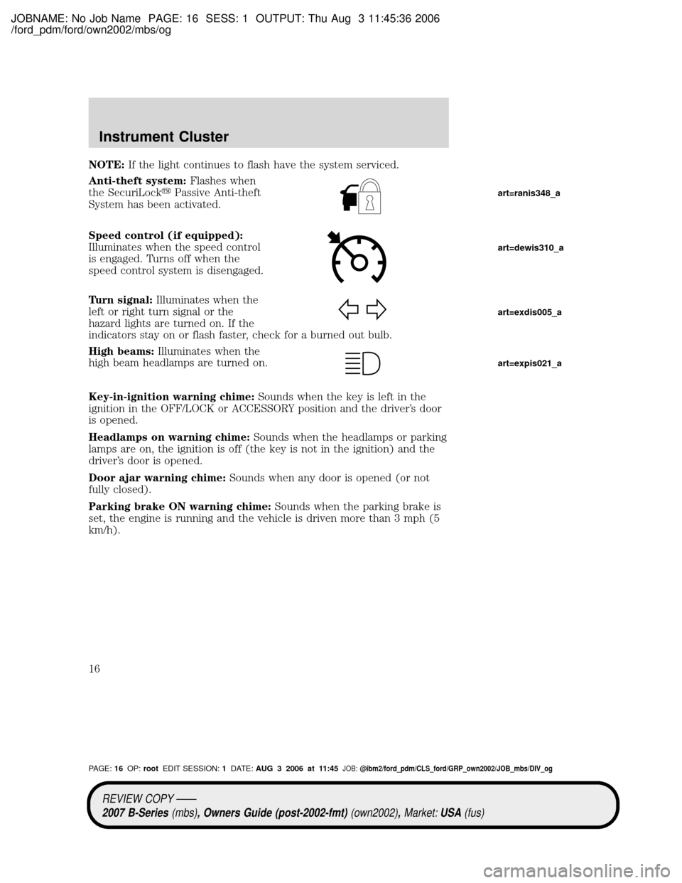
Anti-theft system:Flashes when
the SecuriLockyPassive Anti-theft
System has been activated.
Speed control (if equipped):
Illuminates when the speed control
is engaged. Turns off when the
speed control system is disengaged.
Turn signal:Illuminates when the
left or right turn signal or the
hazard lights are turned on. If the
indicators stay on or flash faster, check for a burned out bulb.
High beams:Illuminates when the
high beam headlamps are turned on.
Key-in-ignition warning chime:Sounds when the key is left in the
ignition in the OFF/LOCK or ACCESSORY position and the driver's door
is opened.
Headlamps on warning chime:Sounds when the headlamps or parking
lamps are on, the ignition is off (the key is not in the ignition) and the
driver's door is opened.
Door ajar warning chime:Sounds when any door is opened (or not
fully closed).
Parking brake ON warning chime:Sounds when the parking brake is
set, the engine is running and the vehicle is driven more than 3 mph (5
km/h).
art=ranis348_a
art=dewis310_a
art=exdis005_a
art=expis021_a
REVIEW COPY ÐÐ
2007 B-Series(mbs), Owners Guide (post-2002-fmt)(own2002),Market:USA(fus)
PAGE:16OP:rootEDIT SESSION:1DATE:AUG 3 2006 at 11:45JOB:@ibm2/ford_pdm/CLS_ford/GRP_own2002/JOB_mbs/DIV_og
Instrument Cluster
16
Page 66 of 279

JOBNAME: No Job Name PAGE: 66 SESS: 1 OUTPUT: Thu Aug 3 11:45:36 2006
/ford_pdm/ford/own2002/mbs/og
KEYS
The key operates all locks on your vehicle. You should always carry a
second key with you in a safe place in case you require it in an
emergency.
If your vehicle is equipped with the SecuriLockyPassive Anti-theft
system, your keys are coded to your vehicle; using a non-coded key will
not permit your vehicle to start. If you lose your dealer supplied keys,
replacement keys are available through your authorized dealer.
POWER DOOR LOCKS (IF EQUIPPED)
Press the top of the control to
unlock all doors and the bottom to
lock all doors.
REMOTE ENTRY SYSTEM (IF EQUIPPED)
This device complies with part 15 of the FCC rules and with RS-210 of
Industry Canada. Operation is subject to the following two conditions:
(1) This device may not cause harmful interference, and (2) This device
must accept any interference received, including interference that may
cause undesired operation.
Changes or modifications not expressly approved by the party
responsible for compliance could void the user's authority to
operate the equipment.
The typical operating range for your remote entry transmitter is
approximately 33 feet (10 meters). A decrease in operating range could
be caused by:
²weather conditions,
²nearby radio towers,
²structures around the vehicle, or
²other vehicles parked next to your vehicle.
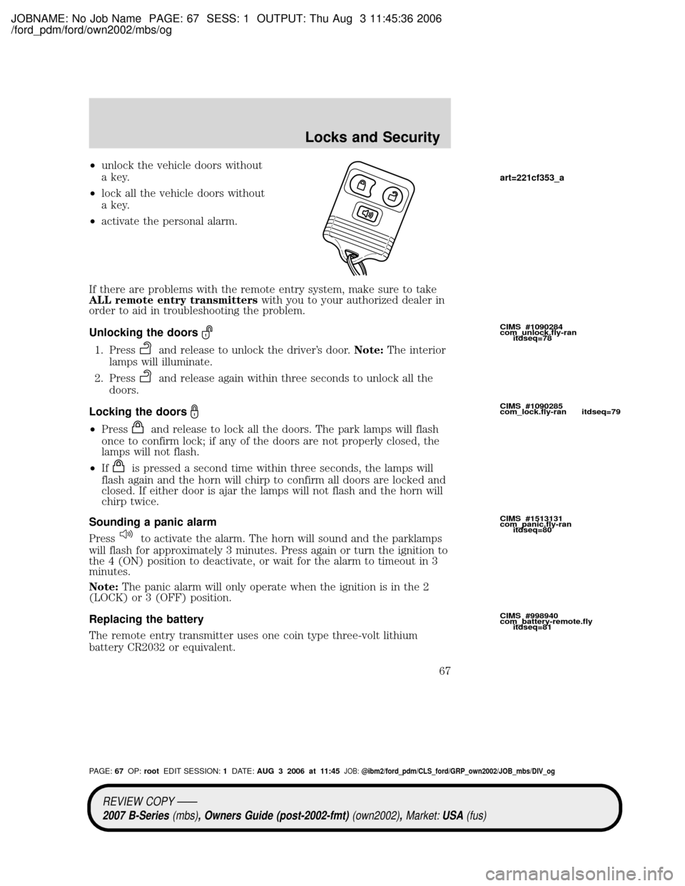
Your vehicle is equipped with a remote entry system which allows you to:
UNLOCK
LOCK
CIMS #1556896
com_keys.ran itdseq=73
CIMS #83545
com_powerdoor-title.ie
itdseq=74
CIMS #101856
com_power-doors.03
itdseq=75
CIMS #1392205
com_remote-title-ie.fly
itdseq=76
CIMS #1031085
com_rem-entry.fly-panic
itdseq=77
art=rancf508_a
REVIEW COPY ÐÐ
2007 B-Series(mbs), Owners Guide (post-2002-fmt)(own2002),Market:USA(fus)
PAGE:66OP:rootEDIT SESSION:1DATE:AUG 3 2006 at 11:45JOB:@ibm2/ford_pdm/CLS_ford/GRP_own2002/JOB_mbs/DIV_og
Locks and Security
66
Page 67 of 279
JOBNAME: No Job Name PAGE: 67 SESS: 1 OUTPUT: Thu Aug 3 11:45:36 2006
/ford_pdm/ford/own2002/mbs/og
²unlock the vehicle doors without
a key.
²lock all the vehicle doors without
a key.
²activate the personal alarm.
If there are problems with the remote entry system, make sure to take
ALL remote entry transmitterswith you to your authorized dealer in
order to aid in troubleshooting the problem.
Unlocking the doors
1. Pressand release to unlock the driver's door.Note:The interior
lamps will illuminate.
2. Press
and release again within three seconds to unlock all the
doors.
Locking the doors
²Pressand release to lock all the doors. The park lamps will flash
once to confirm lock; if any of the doors are not properly closed, the
lamps will not flash.
²If
is pressed a second time within three seconds, the lamps will
flash again and the horn will chirp to confirm all doors are locked and
closed. If either door is ajar the lamps will not flash and the horn will
chirp twice.
Sounding a panic alarm
Press
to activate the alarm. The horn will sound and the parklamps
will flash for approximately 3 minutes. Press again or turn the ignition to
the 4 (ON) position to deactivate, or wait for the alarm to timeout in 3
minutes.
Note:The panic alarm will only operate when the ignition is in the 2
(LOCK) or 3 (OFF) position.
Replacing the battery
The remote entry transmitter uses one coin type three-volt lithium
battery CR2032 or equivalent.
CIMS #1090284
com_unlock.fly-ran
itdseq=78
CIMS #1090285
com_lock.fly-ran itdseq=79
CIMS #1513131
com_panic.fly-ran
itdseq=80
CIMS #998940
com_battery-remote.fly
itdseq=81
art=221cf353_a
REVIEW COPY ÐÐ
2007 B-Series(mbs), Owners Guide (post-2002-fmt)(own2002),Market:USA(fus)
PAGE:67OP:rootEDIT SESSION:1DATE:AUG 3 2006 at 11:45JOB:@ibm2/ford_pdm/CLS_ford/GRP_own2002/JOB_mbs/DIV_og
Locks and Security
67
Page 69 of 279
JOBNAME: No Job Name PAGE: 69 SESS: 1 OUTPUT: Thu Aug 3 11:45:36 2006
/ford_pdm/ford/own2002/mbs/og
Note:Ensure the brake pedal is not
depressed during this sequence.
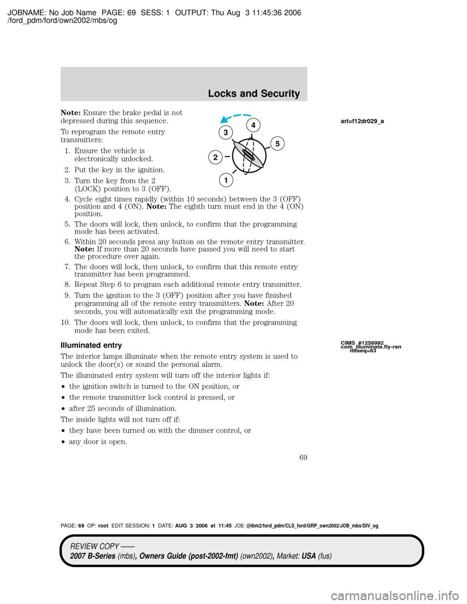
To reprogram the remote entry
transmitters:
1. Ensure the vehicle is
electronically unlocked.
2. Put the key in the ignition.
3. Turn the key from the 2
(LOCK) position to 3 (OFF).
4. Cycle eight times rapidly (within 10 seconds) between the 3 (OFF)
position and 4 (ON).Note:The eighth turn must end in the 4 (ON)
position.
5. The doors will lock, then unlock, to confirm that the programming
mode has been activated.
6. Within 20 seconds press any button on the remote entry transmitter.
Note:If more than 20 seconds have passed you will need to start
the procedure over again.
7. The doors will lock, then unlock, to confirm that this remote entry
transmitter has been programmed.
8. Repeat Step 6 to program each additional remote entry transmitter.
9. Turn the ignition to the 3 (OFF) position after you have finished
programming all of the remote entry transmitters.Note:After 20
seconds, you will automatically exit the programming mode.
10. The doors will lock, then unlock, to confirm that the programming
mode has been exited.
Illuminated entry
The interior lamps illuminate when the remote entry system is used to
unlock the door(s) or sound the personal alarm.
The illuminated entry system will turn off the interior lights if:
²the ignition switch is turned to the ON position, or
²the remote transmitter lock control is pressed, or
²after 25 seconds of illumination.
The inside lights will not turn off if:
²they have been turned on with the dimmer control, or
²any door is open.
3
2
1
5
4
CIMS #1258992
com_illuminate.fly-ran
itdseq=83
art=f12dr029_a
REVIEW COPY ÐÐ
2007 B-Series(mbs), Owners Guide (post-2002-fmt)(own2002),Market:USA(fus)
PAGE:69OP:rootEDIT SESSION:1DATE:AUG 3 2006 at 11:45JOB:@ibm2/ford_pdm/CLS_ford/GRP_own2002/JOB_mbs/DIV_og
Locks and Security
69
Page 75 of 279
JOBNAME: No Job Name PAGE: 75 SESS: 1 OUTPUT: Thu Aug 3 11:45:36 2006
/ford_pdm/ford/own2002/mbs/og
To return seat to original position, slide the seat bottom back, then push
the seatback up to lock it in place. The seat will lock, and you will have
to use the release bar to move the seat back to the original position.
REAR SEATS
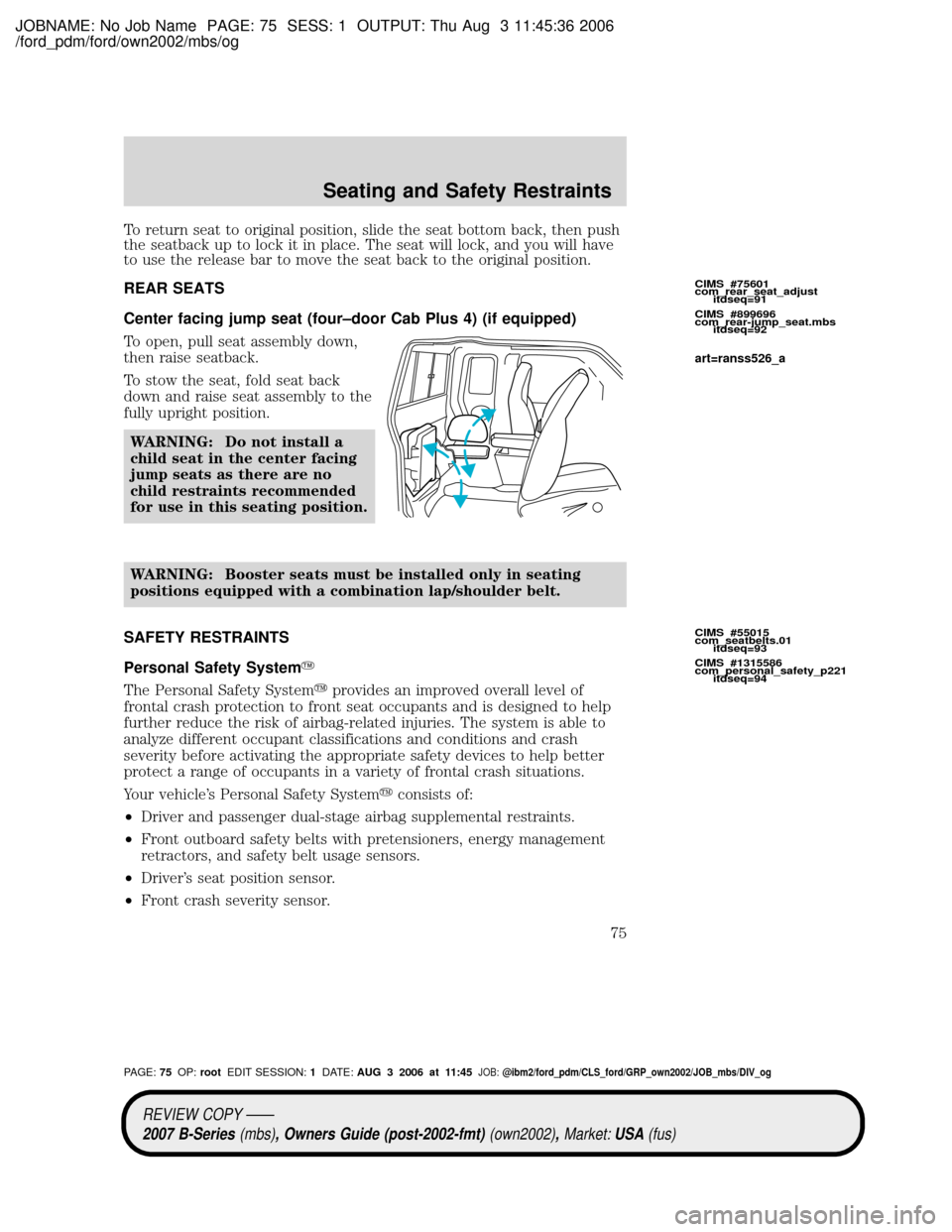
Center facing jump seat (four±door Cab Plus 4) (if equipped)
To open, pull seat assembly down,
then raise seatback.
To stow the seat, fold seat back
down and raise seat assembly to the
fully upright position.
WARNING: Do not install a
child seat in the center facing
jump seats as there are no
child restraints recommended
for use in this seating position.
WARNING: Booster seats must be installed only in seating
positions equipped with a combination lap/shoulder belt.
SAFETY RESTRAINTS
Personal Safety SystemY
The Personal Safety Systemyprovides an improved overall level of
frontal crash protection to front seat occupants and is designed to help
further reduce the risk of airbag-related injuries. The system is able to
analyze different occupant classifications and conditions and crash
severity before activating the appropriate safety devices to help better
protect a range of occupants in a variety of frontal crash situations.
Your vehicle's Personal Safety Systemyconsists of:
²Driver and passenger dual-stage airbag supplemental restraints.
²Front outboard safety belts with pretensioners, energy management
retractors, and safety belt usage sensors.
²Driver's seat position sensor.
²Front crash severity sensor.
CIMS #75601
com_rear_seat_adjust
itdseq=91
CIMS #899696
com_rear-jump_seat.mbs
itdseq=92
CIMS #55015
com_seatbelts.01
itdseq=93
CIMS #1315586
com_personal_safety_p221
itdseq=94
art=ranss526_a
REVIEW COPY ÐÐ
2007 B-Series(mbs), Owners Guide (post-2002-fmt)(own2002),Market:USA(fus)
PAGE:75OP:rootEDIT SESSION:1DATE:AUG 3 2006 at 11:45JOB:@ibm2/ford_pdm/CLS_ford/GRP_own2002/JOB_mbs/DIV_og
Seating and Safety Restraints
75
Page 80 of 279
JOBNAME: No Job Name PAGE: 80 SESS: 1 OUTPUT: Thu Aug 3 11:45:36 2006
/ford_pdm/ford/own2002/mbs/og
WARNING: On Cab Plus 4 vehicles, do not open the rear door
when the rear safety belt is still buckled.
Combination lap and shoulder belts
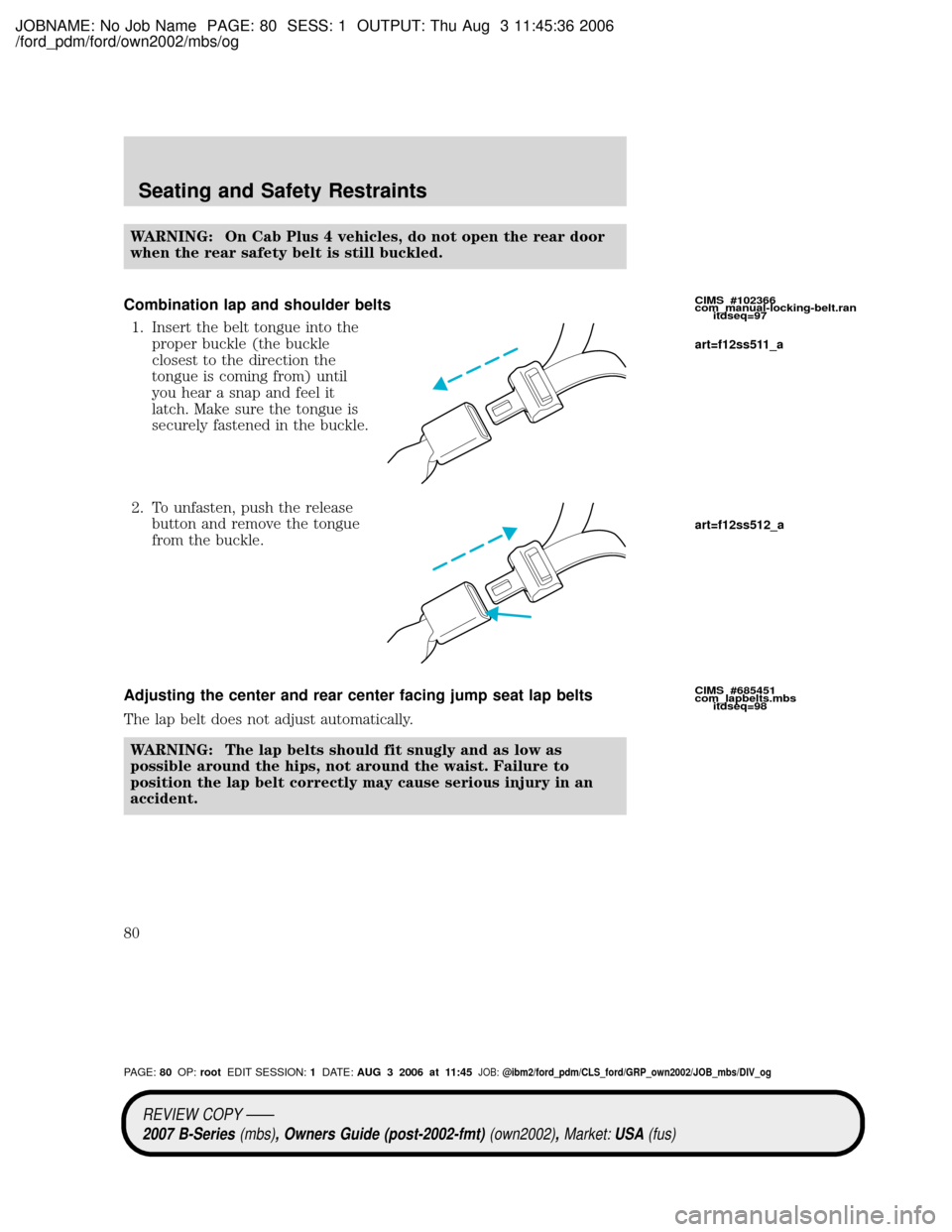
1. Insert the belt tongue into the
proper buckle (the buckle
closest to the direction the
tongue is coming from) until
you hear a snap and feel it
latch. Make sure the tongue is
securely fastened in the buckle.
2. To unfasten, push the release
button and remove the tongue
from the buckle.
Adjusting the center and rear center facing jump seat lap belts
The lap belt does not adjust automatically.
WARNING: The lap belts should fit snugly and as low as
possible around the hips, not around the waist. Failure to
position the lap belt correctly may cause serious injury in an
accident.
CIMS #102366
com_manual-locking-belt.ran
itdseq=97
CIMS #685451
com_lapbelts.mbs
itdseq=98
art=f12ss511_a
art=f12ss512_a
REVIEW COPY ÐÐ
2007 B-Series(mbs), Owners Guide (post-2002-fmt)(own2002),Market:USA(fus)
PAGE:80OP:rootEDIT SESSION:1DATE:AUG 3 2006 at 11:45JOB:@ibm2/ford_pdm/CLS_ford/GRP_own2002/JOB_mbs/DIV_og
Seating and Safety Restraints
80
Page 81 of 279
JOBNAME: No Job Name PAGE: 81 SESS: 1 OUTPUT: Thu Aug 3 11:45:36 2006
/ford_pdm/ford/own2002/mbs/og
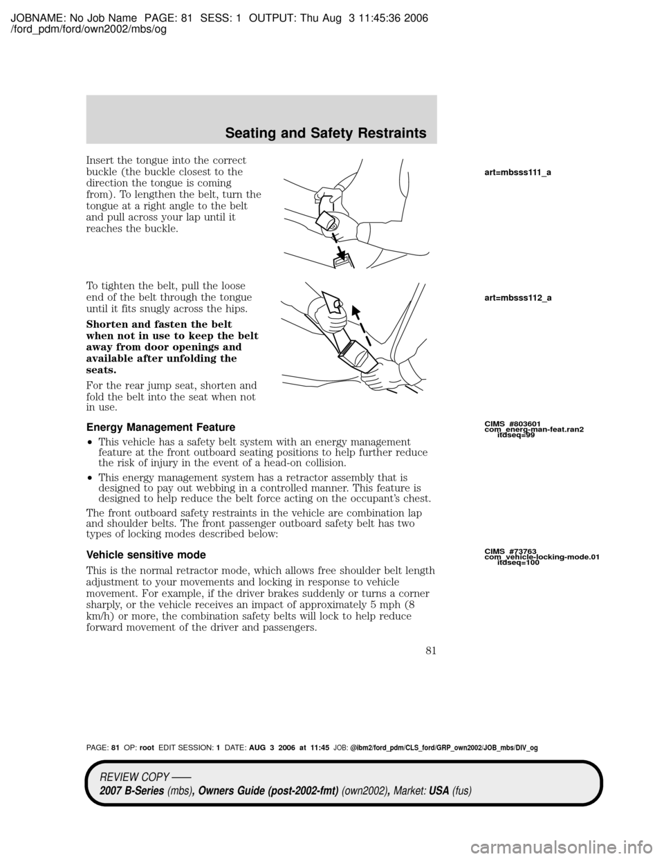
Insert the tongue into the correct
buckle (the buckle closest to the
direction the tongue is coming
from). To lengthen the belt, turn the
tongue at a right angle to the belt
and pull across your lap until it
reaches the buckle.
To tighten the belt, pull the loose
end of the belt through the tongue
until it fits snugly across the hips.
Shorten and fasten the belt
when not in use to keep the belt
away from door openings and
available after unfolding the
seats.
For the rear jump seat, shorten and
fold the belt into the seat when not
in use.
Energy Management Feature
²This vehicle has a safety belt system with an energy management
feature at the front outboard seating positions to help further reduce
the risk of injury in the event of a head-on collision.
²This energy management system has a retractor assembly that is
designed to pay out webbing in a controlled manner. This feature is
designed to help reduce the belt force acting on the occupant's chest.
The front outboard safety restraints in the vehicle are combination lap
and shoulder belts. The front passenger outboard safety belt has two
types of locking modes described below:
Vehicle sensitive mode
This is the normal retractor mode, which allows free shoulder belt length
adjustment to your movements and locking in response to vehicle
movement. For example, if the driver brakes suddenly or turns a corner
sharply, or the vehicle receives an impact of approximately 5 mph (8
km/h) or more, the combination safety belts will lock to help reduce
forward movement of the driver and passengers.
CIMS #803601
com_energ-man-feat.ran2
itdseq=99
CIMS #73763
com_vehicle-locking-mode.01
itdseq=100
art=mbsss111_a
art=mbsss112_a
REVIEW COPY ÐÐ
2007 B-Series(mbs), Owners Guide (post-2002-fmt)(own2002),Market:USA(fus)
PAGE:81OP:rootEDIT SESSION:1DATE:AUG 3 2006 at 11:45JOB:@ibm2/ford_pdm/CLS_ford/GRP_own2002/JOB_mbs/DIV_og
Seating and Safety Restraints
81
Page 84 of 279
JOBNAME: No Job Name PAGE: 84 SESS: 1 OUTPUT: Thu Aug 3 11:45:36 2006
/ford_pdm/ford/own2002/mbs/og
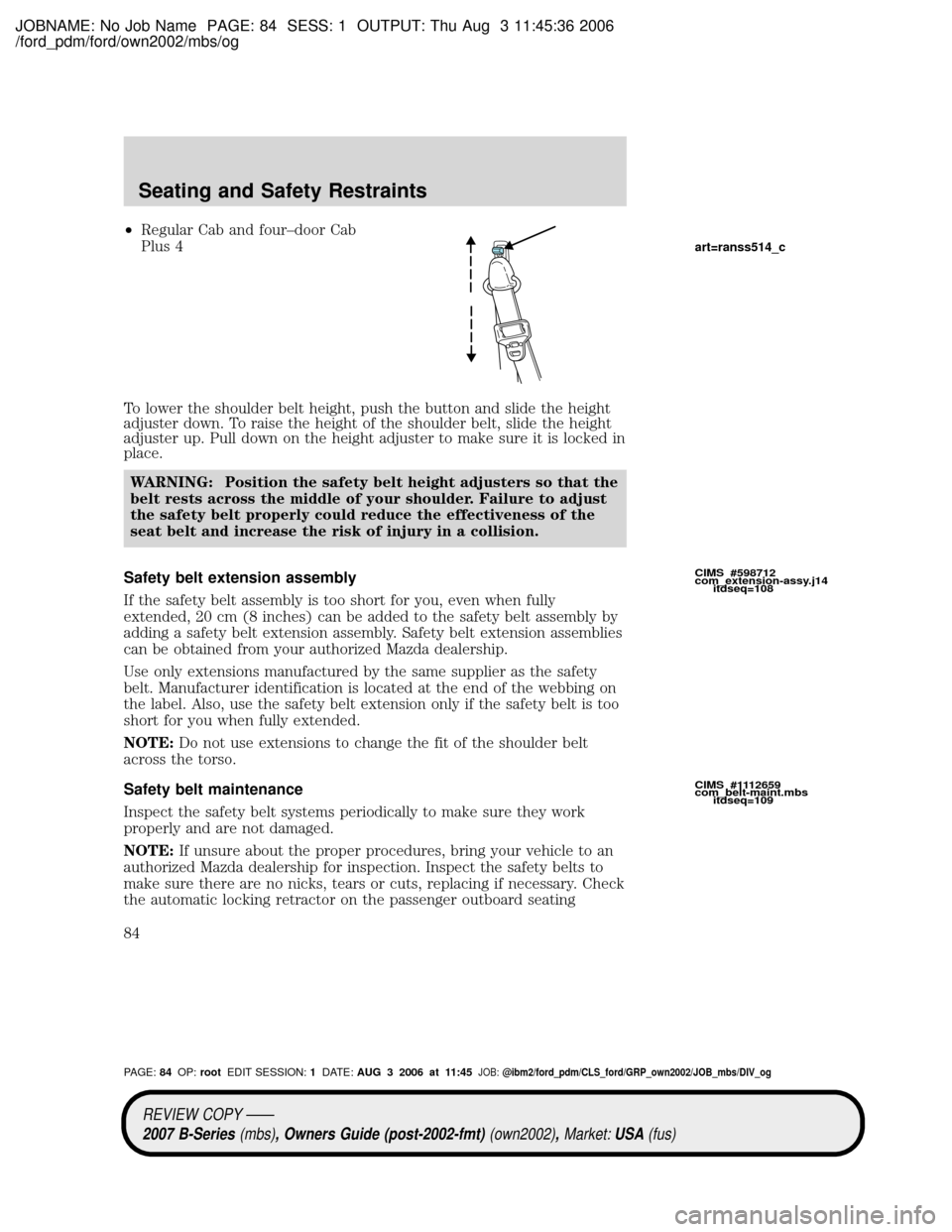
²Regular Cab and four±door Cab
Plus 4
To lower the shoulder belt height, push the button and slide the height
adjuster down. To raise the height of the shoulder belt, slide the height
adjuster up. Pull down on the height adjuster to make sure it is locked in
place.
WARNING: Position the safety belt height adjusters so that the
belt rests across the middle of your shoulder. Failure to adjust
the safety belt properly could reduce the effectiveness of the
seat belt and increase the risk of injury in a collision.
Safety belt extension assembly
If the safety belt assembly is too short for you, even when fully
extended, 20 cm (8 inches) can be added to the safety belt assembly by
adding a safety belt extension assembly. Safety belt extension assemblies
can be obtained from your authorized Mazda dealership.
Use only extensions manufactured by the same supplier as the safety
belt. Manufacturer identification is located at the end of the webbing on
the label. Also, use the safety belt extension only if the safety belt is too
short for you when fully extended.
NOTE:Do not use extensions to change the fit of the shoulder belt
across the torso.
Safety belt maintenance
Inspect the safety belt systems periodically to make sure they work
properly and are not damaged.
NOTE:If unsure about the proper procedures, bring your vehicle to an
authorized Mazda dealership for inspection. Inspect the safety belts to
make sure there are no nicks, tears or cuts, replacing if necessary. Check
the automatic locking retractor on the passenger outboard seating
CIMS #598712
com_extension-assy.j14
itdseq=108
CIMS #1112659
com_belt-maint.mbs
itdseq=109
art=ranss514_c
REVIEW COPY ÐÐ
2007 B-Series(mbs), Owners Guide (post-2002-fmt)(own2002),Market:USA(fus)
PAGE:84OP:rootEDIT SESSION:1DATE:AUG 3 2006 at 11:45JOB:@ibm2/ford_pdm/CLS_ford/GRP_own2002/JOB_mbs/DIV_og
Seating and Safety Restraints
84
Page 179 of 279
JOBNAME: No Job Name PAGE: 179 SESS: 1 OUTPUT: Thu Aug 3 11:45:36 2006
/ford_pdm/ford/own2002/mbs/og
Fuse/Relay
LocationFuse Amp
RatingPassenger Compartment Fuse
Panel Description
10 10A Cluster (RUN/START), 4x4
module (RUN/START)
11 10A Smart Junction Box (SJB) (Logic
power)
12 15A Audiophile subwoofer amplifier,
Satellite radio
13 15A Horn, Interior lamps
14 15A High beam headlamp, High beam
indicator (cluster)
15 Ð One-touch down relay
16 30A cartridge
fusePower windows
17 15A Turn signals/Hazards
18 Ð Not used
19 20A Center High-Mounted Stop Lamp
(CHMSL)/Stop lamps
20 10A Anti-lock Brake System (ABS)
module, Brake-shift interlock,
Speed control module, Back-up
lamps, Overdrive cancel switch,
Electronic flasher (turn/hazard)
21 5A Starter relay coil
22 5A Radio (START)
23 30A Headlamps (low and high beam)
24 20A Radio battery feed (B+)
25 Ð Accessory relay
26 2A Redundant cruise switch
27 10A Climate control blower relay/blend
doors
28 15A 4x4 module battery feed (B+)
29 20A Cigar lighter, Diagnostic connector
(OBD II)
REVIEW COPY ÐÐ
2007 B-Series(mbs), Owners Guide (post-2002-fmt)(own2002),Market:USA(fus)
PAGE:179OP:rootEDIT SESSION:1DATE:AUG 3 2006 at 11:45JOB:@ibm2/ford_pdm/CLS_ford/GRP_own2002/JOB_mbs/DIV_og
Roadside Emergencies
179
Page 189 of 279
JOBNAME: No Job Name PAGE: 189 SESS: 1 OUTPUT: Thu Aug 3 11:45:36 2006
/ford_pdm/ford/own2002/mbs/og
²Towing a trailer
²Driving vehicles equipped with a camper body
²Driving vehicles with a load on the cargo rack
Drive cautiously when using a full-size dissimilar spare tire/wheel and
seek service as soon as possible.
Full-size Matching Spare Tire/Wheel Information
This spare tire/wheel will match the road tire/wheel. When driving with
the full size matching spare tire/wheel, do not exceed 70 mph (113
km/h). It is intended for temporary use only. This means if you need to
use it, you should replace it as soon as possible.
Location of the spare tire and tools
Note:The tire pressure monitoring system (TPMS) indicator light will
illuminate when the spare is in use. To restore the full functionality of
the TPMS system, all road wheels equipped with the tire pressure
monitoring sensors must be mounted on the vehicle.
Have a flat tire serviced by an authorized dealer in order to prevent
damage to the TPMS sensor, refer toTire Pressure Monitoring System
(TPMS)in theTires, Wheel and Loadingchapter. Replace the spare
tire with a road tire as soon as possible.
The spare tire and tools for your vehicle are stowed in the following
locations:
Tool Location
Spare tire Under the vehicle, just forward of
the rear bumper
Jack, jack handle, wheel nut
wrenchRegular Cab: behind seats and
underneath the jack and tools
cover
Cab Plus 4±Door: stowed behind
the front seats, between jump
seats and underneath jack and
tools cover. The lug wrench is held
in place with a wingnut.
Key, spare tire lock (if equipped) In the glove box
Removing the spare tire
1. Assemble the jack handle to the lug wrench as shown in the
illustrations.
CIMS #1516741
com_full-size-spare
itdseq=224
CIMS #1125281
com_spare-tire.mbs
itdseq=225
REVIEW COPY ÐÐ
2007 B-Series(mbs), Owners Guide (post-2002-fmt)(own2002),Market:USA(fus)
PAGE:189OP:rootEDIT SESSION:1DATE:AUG 3 2006 at 11:45JOB:@ibm2/ford_pdm/CLS_ford/GRP_own2002/JOB_mbs/DIV_og
Roadside Emergencies
189