ABS MAZDA MODEL B4000 2003 Owners Manual
[x] Cancel search | Manufacturer: MAZDA, Model Year: 2003, Model line: MODEL B4000, Model: MAZDA MODEL B4000 2003Pages: 250, PDF Size: 2.85 MB
Page 10 of 250

C012
3
4
5
6
RPMx1000
ABS!BRAKE
CHECK
ENGINE
CHECK FUEL CAP
E FH
H
HP
RN D 2 1THEFT
SPEED
CONT
4WD
HIGH 4WD
LOW
O/D
OFFL
L
10MPH
20 50
60
70
30 40
80
90
km/h
0 0 0
101
00
1
20
10 0 0 0 0 040 60
80
100
120
140
160180
20
DOOR
AJAR
CHECK
GAGE
DIM
OFF
SET
ACC
COAST
OFF
ON
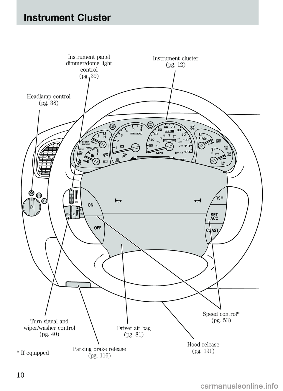
Headlamp control
(pg. 38) Instrument panel
dimmer/dome light control
(pg. 39) Instrument cluster
(pg. 12)
Speed control*(pg. 53)
Hood release (pg. 191)
Driver air bag
(pg. 81)
Parking brake release (pg. 116)
Turn signal and
wiper/washer control (pg. 40)
* If equipped
Instrument Cluster
10
Page 14 of 250

position. If the brake system warning light does not illuminate at this
time, seek service immediately from your dealership. Illumination after
releasing the parking brake indicates low brake fluid level and the brake
system should be inspected immediately by your servicing dealership.WARNING: Driving a vehicle with the brake system warning
light on is dangerous. A significant decrease in braking
performance may occur. It will take you longer to stop the
vehicle. Have the vehicle checked by your dealer immediately.
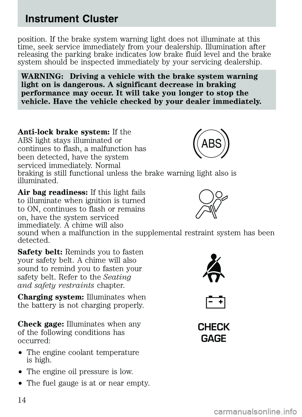
Anti-lock brake system: If the
ABS light stays illuminated or
continues to flash, a malfunction has
been detected, have the system
serviced immediately. Normal
braking is still functional unless the brake warning light also is
illuminated.
Air bag readiness: If this light fails
to illuminate when ignition is turned
to ON, continues to flash or remains
on, have the system serviced
immediately. A chime will also
sound when a malfunction in the supplemental restraint system has been
detected.
Safety belt: Reminds you to fasten
your safety belt. A chime will also
sound to remind you to fasten your
safety belt. Refer to the Seating
and safety restraints chapter.
Charging system: Illuminates when
the battery is not charging properly.
Check gage: Illuminates when any
of the following conditions has
occurred:
• The engine coolant temperature
is high.
• The engine oil pressure is low.
• The fuel gauge is at or near empty.
ABS
CHECK
GAGE
Instrument Cluster
14
Page 43 of 250

To install the new bulb:
Handle a halogen headlamp bulb carefully and keep out of
children’s reach. Grasp the bulb only by its plastic base and do
not touch the glass. The oil from your hands could cause the bulb
to break the next time the headlamps are operated. Always wear
safety glasses while handling bulbs.
NOTE: If the bulb is accidentally touched, it should be cleaned with
rubbing alcohol before being used.1. With the flat side of the bulb’s plastic base facing upward, insert the glass end of the bulb into the lamp assembly. You may need to turn
the bulb left or right to align the grooves in the plastic base with the
tabs in the lamp assembly. When the grooves are aligned, push the
bulb into the lamp assembly until the plastic base contacts the rear
of the lamp assembly.
2. Install the bulb retaining ring over the plastic base until it contacts the rear of the socket by rotating clockwise until you feel a “stop.”
3. Install the electrical connector into the plastic base until it snaps, locking it into position.
4. Install the headlamp on vehicle, push rearward and secure with two retainer pins.
5. Turn the headlamps on and make sure they work properly. If the headlamp was correctly aligned before you changed the bulb, you
should not need to align it again.
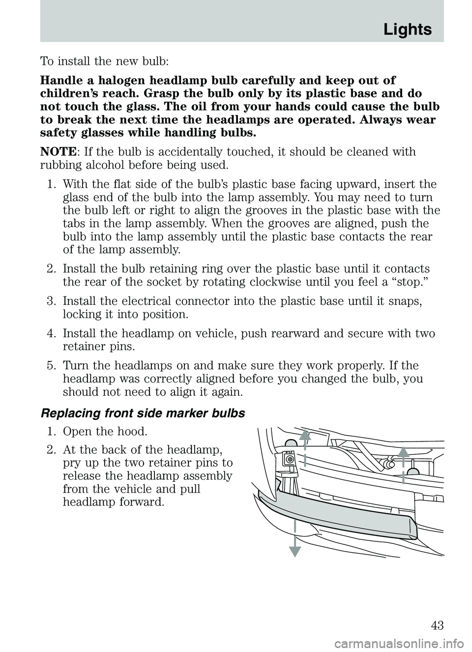
Replacing front side marker bulbs 1. Open the hood.
2. At the back of the headlamp, pry up the two retainer pins to
release the headlamp assembly
from the vehicle and pull
headlamp forward.
Lights
43
Page 81 of 250

The energy absorbing functions may have been activated in a collision so
the restraints should be examined; if the front air bags have deployed,
the pretensioners have also deployed and must be replaced — regardless
of whether there was an occupant in the passenger seat or not.WARNING: Failure to inspect and if necessary replace the
safety belt assembly under the above conditions could result in
severe personal injuries in the event of a collision.
Refer to Interior in theCleaning chapter.
AIR BAG SUPPLEMENTAL RESTRAINT SYSTEM (SRS)
Important supplemental restraint system (SRS) precautions
The supplemental restraint system is designed to work with the safety
belt to help protect the driver and right front passenger from certain
upper body injuries.
WARNING: Air bags DO NOT
inflate slowly or gently and the
risk of injury from a deploying
air bag is greatest close to the
trim covering the air bag
module. Always wear your
safety belt.
Seating and Safety Restraints
81
Page 113 of 250

•steering wheel is turned when getting in or out of the vehicle
Make sure the corresponding lights illuminate or illuminate briefly. If a
light fails to illuminate, have the vehicle serviced.
• If the driver’s safety belt is fastened, the
light may not illuminate.
Refer to the Instrument Cluster chapter for more information.
Starting the engine
Note: Whenever you start your vehicle, release the key as soon as the
engine starts. Excessive cranking could damage the starter.
1. Turn the key to 4 (ON) without turning the key to 5 (START). If
there is difficulty in turning the
key, rotate the steering wheel
until the key turns freely. This
condition may occur when:
• the front wheels are turned
• a front wheel is against the curb
Turn the key to 5 (START), then
release the key as soon as the
engine starts. Excessive cranking could damage the starter.
Note: If the engine does not start within five seconds on the first try,
turn the key to 3 (OFF), wait 10 seconds and try again.
Cold weather starting (flexible fuel vehicles only)
In cold weather, ethanol fuel distributors should supply winter grade
(E
d85) ethanol. If summer grade (Ed85) ethanol is used in cold weather,
you may experience increased cranking times, rough idle or hesitation
C
012
3
4
5
6
RPMx1000
ABS!
BRAKE
CHECK
ENGINE
CHECK FUEL CAP
E FH
H
H
P
RN D 2 1THEFT
SPEED
CONT
4WD
HIGH 4WD
LOW
O/D
OFFL
L
10MPH
20 50
60
70
30 40
80
90
km/h
0 0 0
101
00
1
20
1
0 0 0 0 0 040 60
80
100
120
140
160180
20
DOOR
AJAR
CHECK
GAGE
3
2
1
5
4
Driving
113
Page 115 of 250

WARNING: If you smell exhaust fumes inside your vehicle,
have your dealer inspect your vehicle immediately. Do not drive
if you smell exhaust fumes.
Important ventilating information
If the engine is idling while the vehicle is stopped for a long period of
time, open the windows at least 2.5 cm (one inch) or adjust the heating
or air conditioning to bring in fresh air.
BRAKES
Occasional brake noise is normal. If a metal-to-metal, continuous grinding
or continuous squeal sound is present, the brake linings may be worn-out
and should be inspected by a qualified service technician. If the vehicle
has continuous vibration or shudder in the steering wheel while braking,
the vehicle should be inspected by a qualified service technician.
Four-wheel anti-lock brake system (ABS)
This vehicle is equipped with an anti-lock braking system (ABS), a noise
from the hydraulic pump motor and pulsation in the pedal may be
observed during ABS braking events. Pedal pulsation coupled with noise
while braking under panic conditions or on loose gravel, bumps, wet or
snowy roads is normal and indicates proper functioning of the vehicle’s
anti-lock brake system.
NOTE: The ABS performs a self-check after you start the engine and
begin to drive away.
A brief mechanical noise may be heard during this test. This is normal. If
a malfunction is found, the ABS warning light will come on. If the vehicle
has continuous vibration or shudder in the steering wheel while braking,
the vehicle should be inspected by an authorized Mazda dealership.
The ABS operates by detecting the
onset of wheel lockup during brake
applications and compensates for
this tendency. The wheels are
prevented from locking even when
the brakes are firmly applied. The
accompanying illustration depicts
the advantage of an ABS equipped
vehicle (on bottom) to a non-ABS
equipped vehicle (on top) during hard braking with loss of front braking
traction.
Driving
115
Page 116 of 250

WARNING: The Anti-Lock system does not decrease the time
necessary to apply the brakes or always reduce stopping
distance. Always leave enough room between your vehicle and
the vehicle in front of you to stop.
Using ABS
When hard braking is required, apply continuous force on the brake
pedal; do not pump the brake pedal since this will reduce the
effectiveness of the ABS and will increase your vehicle’s stopping
distance. The ABS will be activated immediately, allowing you to retain
full steering control during hard braking and on slippery surfaces.
However, the ABS does not decrease stopping distance.
ABS warning lamp
ABS
TheABSlamp in the instrument cluster momentarily illuminates when
the ignition is turned to ON. If the light does not illuminate during start
up, remains on or flashes, the ABS may be disabled and may need to be
serviced.
Even when the ABS is disabled,
normal braking is still effective. (If
your BRAKE warning lamp
illuminates with the parking brake
released, have your brake system
serviced immediately.)
Parking brake
Apply the parking brake whenever
the vehicle is parked. To set the
parking brake, press the parking
brake pedal down until the pedal
stops.
!
BRAKE
BRAKE
RELEASE
Driving
116
Page 128 of 250

Driving on snow and ice
A 4WD vehicle has advantages over 2WD vehicles in snow and ice but
can skid like any other vehicle.
Avoid sudden applications of power and quick changes of direction on
snow and ice. Apply the accelerator slowly and steadily when starting
from a full stop.
When braking, apply the brakes as you normally would. In order to allow
the anti-lock brake system (ABS) to operate properly, keep steady
pressure on the brake pedal.
Make sure you allow sufficient distance between you and other vehicles
for stopping. Drive slower than usual and consider using one of the lower
gears.
DRIVING THROUGH WATER
If driving through deep or standing water is unavoidable, proceed very
slowly especially if the depth is not known. Never drive through water
that is higher than the bottom of the hubs (for trucks) or the bottom of
the wheel rims (for cars). Traction or brake capability may be limited
and your vehicle may stall. Water may also enter your engine’s air intake
and severely damage your engine.
Once through the water, always dry the brakes by moving your vehicle
slowly while applying light pressure on the brake pedal. Wet brakes do
not stop the vehicle as quickly as dry brakes.Driving through deep
water where the transmission vent tube is submerged may allow
water into the transmission and cause internal transmission
damage.
SPECIAL LOADING INSTRUCTIONS FOR OWNERS OF PICKUP
TRUCKS AND UTILITY-TYPE VEHICLES
WARNING: For important information regarding safe operation
of this type of vehicle, see the Preparing to drive your vehicle
section in this chapter.
WARNING: Loaded vehicles may handle differently than
unloaded vehicles. Extra precautions, such as slower speeds and
increased stopping distance, should be taken when driving a
heavily loaded vehicle.
Your vehicle can haul more cargo and people than most passenger cars.
Depending upon the type and placement of the load, hauling cargo and
people may raise the center of gravity of the vehicle.
Driving
128
Page 143 of 250

Fuse/RelayLocation Fuse Amp
Rating Passenger Compartment Fuse
Panel Description
8 — Not used
9 7.5A Brake pedal position switch
10 7.5A Speed control servo/amplifier assembly, Generic Electronic
Module (GEM), Shift lock
actuator, Turn signals, 4x4
11 7.5A Instrument cluster, 4x4, Main light switch, Central Security Module
(CSM), Generic Electronic Module
(GEM)
12 — Not used
13 20A Brake pedal position switch
14 10A Anti-lock Brake System (ABS) control module
15 — Not used
16 30A Windshield wiper motor, Wiper HI/LO relay, Wiper run/park relay
17 20A Cigar lighter, Data Link Connector (DLC)
18 — Not used
19 25A Powertrain Control Module (PCM) power diode, Ignition, PATS
(Passive Anti-Theft System)
20 7.5A Generic Electronic Module (GEM), Radio
21 15A Hazard flasher
22 20A Auxiliary power socket
23 — Not used
24 7.5A Clutch Pedal Position (CPP) switch, Starter interrupt relay
25 — Not used
Roadside Emergencies
143
Page 145 of 250

WARNING: To reduce risk of electrical shock, always replace
the cover to the Power Distribution Box before reconnecting
the battery or refilling fluid reservoirs.
If the battery has been disconnected and reconnected, refer to the
Battery section of the Maintenance and specifications chapter.
2.3L engine (if equipped)
The high-current fuses are coded as follows:
Fuse/Relay Location Fuse Amp
Rating Power Distribution Box
Description
1 50A** I/P fuse panel
2 — Not used
3 — Not used
4 — Not used
5 — Not used
6 50A** Anti-lock Brake System (ABS)
pump motor
7 30A* Powertrain Control Module (PCM)
1234521 22 23 24
25 26 27 28
29 30 31 32
33 34 35 36
37 38 39 40
41 42 43 44
678910 55
49
48 54
5352
51 56
56 B
56 A
50 50 B
50 A
47
45 45 B
45 A
4646 B
46 A
11 12 13 14 15
16 17 18 19 20
Roadside Emergencies
145