air condition MAZDA MODEL B4000 2003 Owners Manual
[x] Cancel search | Manufacturer: MAZDA, Model Year: 2003, Model line: MODEL B4000, Model: MAZDA MODEL B4000 2003Pages: 250, PDF Size: 2.85 MB
Page 1 of 250
Introduction4
Instrument Cluster 10
Warning and control lights 12
Gauges 16
Entertainment Systems19
AM/FM stereo 19
AM/FM stereo with CD 21
AM/FM stereo with in-dash six CD 24
AM/FM stereo with CD/MP3 27
Climate Controls35
Manual heating and air conditioning 35
Lights38
Headlamps 38
Turn signal control 40
Bulb replacement 40
Driver Controls47
Windshield wiper/washer control 47
Steering wheel adjustment 48
Power windows 49
Speed control 53
Locks and Security59
Keys 59
Locks 59
Anti-theft system 59
Table of Contents
1
Page 12 of 250
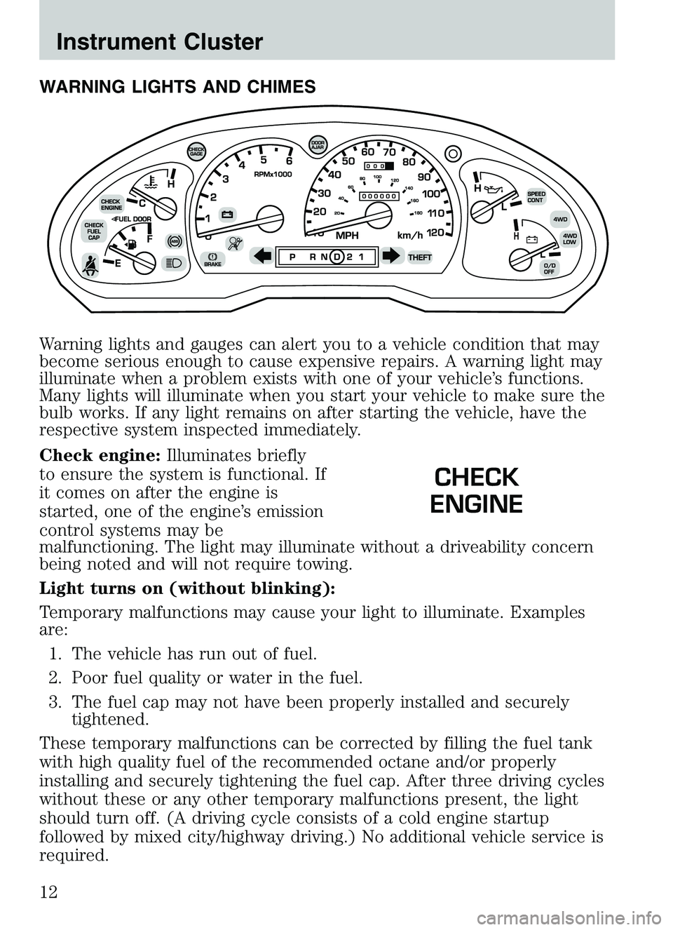
WARNING LIGHTS AND CHIMES
Warning lights and gauges can alert you to a vehicle condition that may
become serious enough to cause expensive repairs. A warning light may
illuminate when a problem exists with one of your vehicle’s functions.
Many lights will illuminate when you start your vehicle to make sure the
bulb works. If any light remains on after starting the vehicle, have the
respective system inspected immediately.
Check engine:Illuminates briefly
to ensure the system is functional. If
it comes on after the engine is
started, one of the engine’s emission
control systems may be
malfunctioning. The light may illuminate without a driveability concern
being noted and will not require towing.
Light turns on (without blinking):
Temporary malfunctions may cause your light to illuminate. Examples
are:
1. The vehicle has run out of fuel.
2. Poor fuel quality or water in the fuel.
3. The fuel cap may not have been properly installed and securely tightened.
These temporary malfunctions can be corrected by filling the fuel tank
with high quality fuel of the recommended octane and/or properly
installing and securely tightening the fuel cap. After three driving cycles
without these or any other temporary malfunctions present, the light
should turn off. (A driving cycle consists of a cold engine startup
followed by mixed city/highway driving.) No additional vehicle service is
required.
CHECK
ENGINE
Instrument Cluster
12
Page 14 of 250
position. If the brake system warning light does not illuminate at this
time, seek service immediately from your dealership. Illumination after
releasing the parking brake indicates low brake fluid level and the brake
system should be inspected immediately by your servicing dealership.WARNING: Driving a vehicle with the brake system warning
light on is dangerous. A significant decrease in braking
performance may occur. It will take you longer to stop the
vehicle. Have the vehicle checked by your dealer immediately.
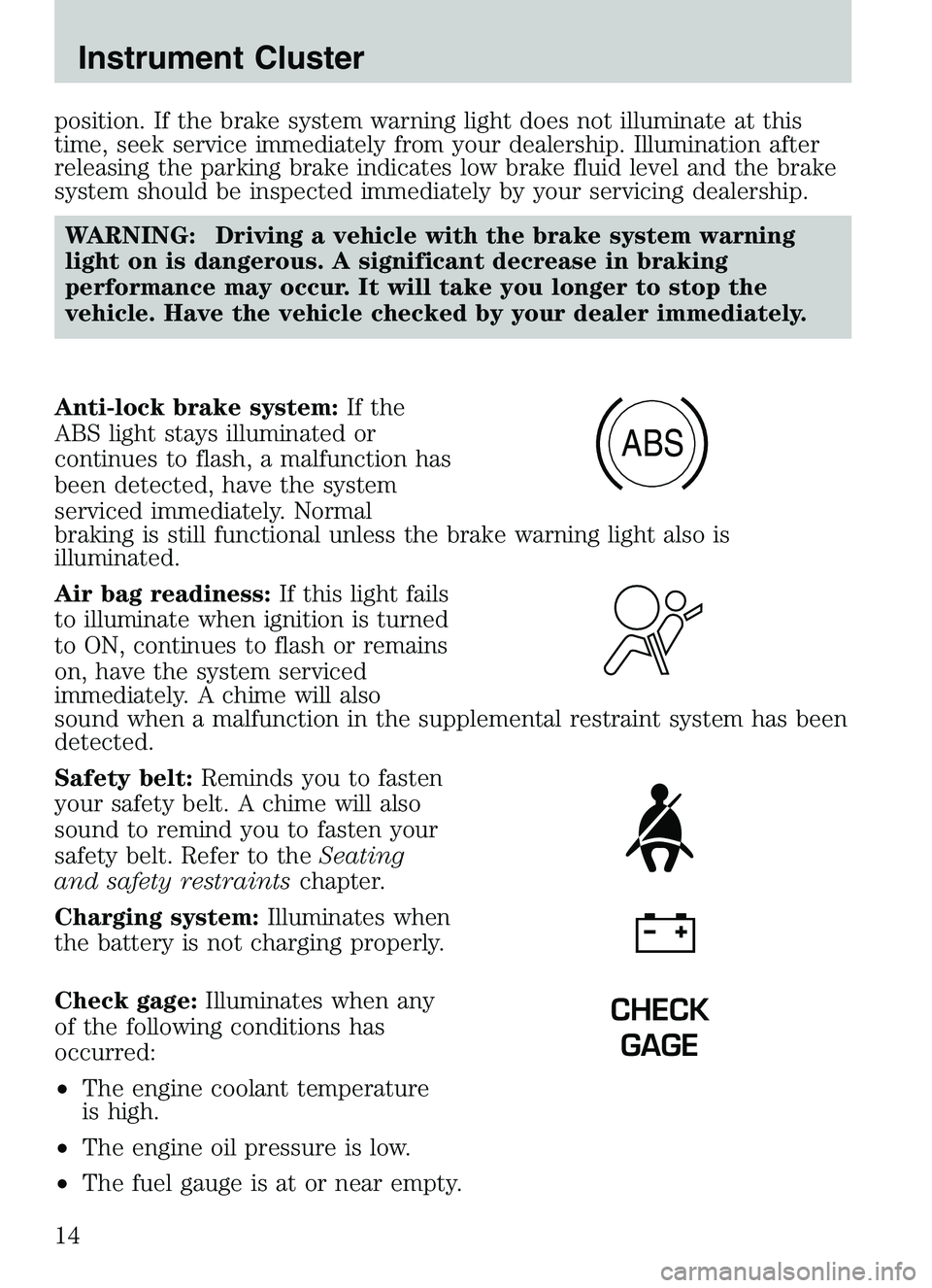
Anti-lock brake system: If the
ABS light stays illuminated or
continues to flash, a malfunction has
been detected, have the system
serviced immediately. Normal
braking is still functional unless the brake warning light also is
illuminated.
Air bag readiness: If this light fails
to illuminate when ignition is turned
to ON, continues to flash or remains
on, have the system serviced
immediately. A chime will also
sound when a malfunction in the supplemental restraint system has been
detected.
Safety belt: Reminds you to fasten
your safety belt. A chime will also
sound to remind you to fasten your
safety belt. Refer to the Seating
and safety restraints chapter.
Charging system: Illuminates when
the battery is not charging properly.
Check gage: Illuminates when any
of the following conditions has
occurred:
• The engine coolant temperature
is high.
• The engine oil pressure is low.
• The fuel gauge is at or near empty.
ABS
CHECK
GAGE
Instrument Cluster
14
Page 35 of 250
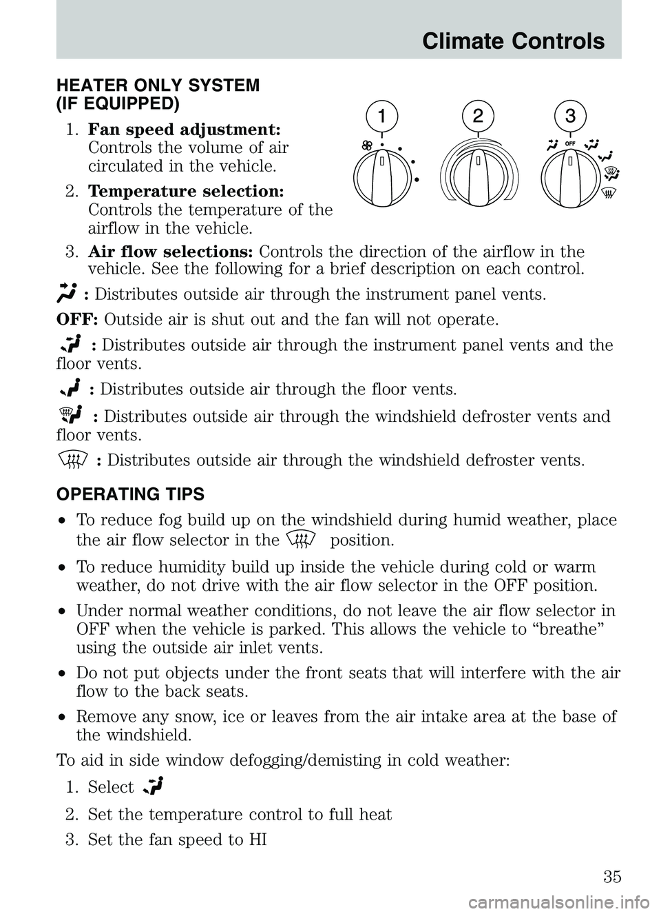
HEATER ONLY SYSTEM
(IF EQUIPPED)1. Fan speed adjustment:
Controls the volume of air
circulated in the vehicle.
2. Temperature selection:
Controls the temperature of the
airflow in the vehicle.
3. Air flow selections: Controls the direction of the airflow in the
vehicle. See the following for a brief description on each control.
: Distributes outside air through the instrument panel vents.
OFF: Outside air is shut out and the fan will not operate.
:Distributes outside air through the instrument panel vents and the
floor vents.
: Distributes outside air through the floor vents.
:Distributes outside air through the windshield defroster vents and
floor vents.
: Distributes outside air through the windshield defroster vents.
OPERATING TIPS
• To reduce fog build up on the windshield during humid weather, place
the air flow selector in the
position.
• To reduce humidity build up inside the vehicle during cold or warm
weather, do not drive with the air flow selector in the OFF position.
• Under normal weather conditions, do not leave the air flow selector in
OFF when the vehicle is parked. This allows the vehicle to “breathe”
using the outside air inlet vents.
• Do not put objects under the front seats that will interfere with the air
flow to the back seats.
• Remove any snow, ice or leaves from the air intake area at the base of
the windshield.
To aid in side window defogging/demisting in cold weather:
1. Select
2. Set the temperature control to full heat
3. Set the fan speed to HI
Climate Controls
35
Page 36 of 250
4. Direct the outer instrument panel vents towards the side windows
To increase airflow to the outer instrument panel vents, close the vents
located in the middle of the instrument panel.
WARNING: Do not place objects on top of the instrument panel
as these objects may become projectiles in a collision or sudden
stop.
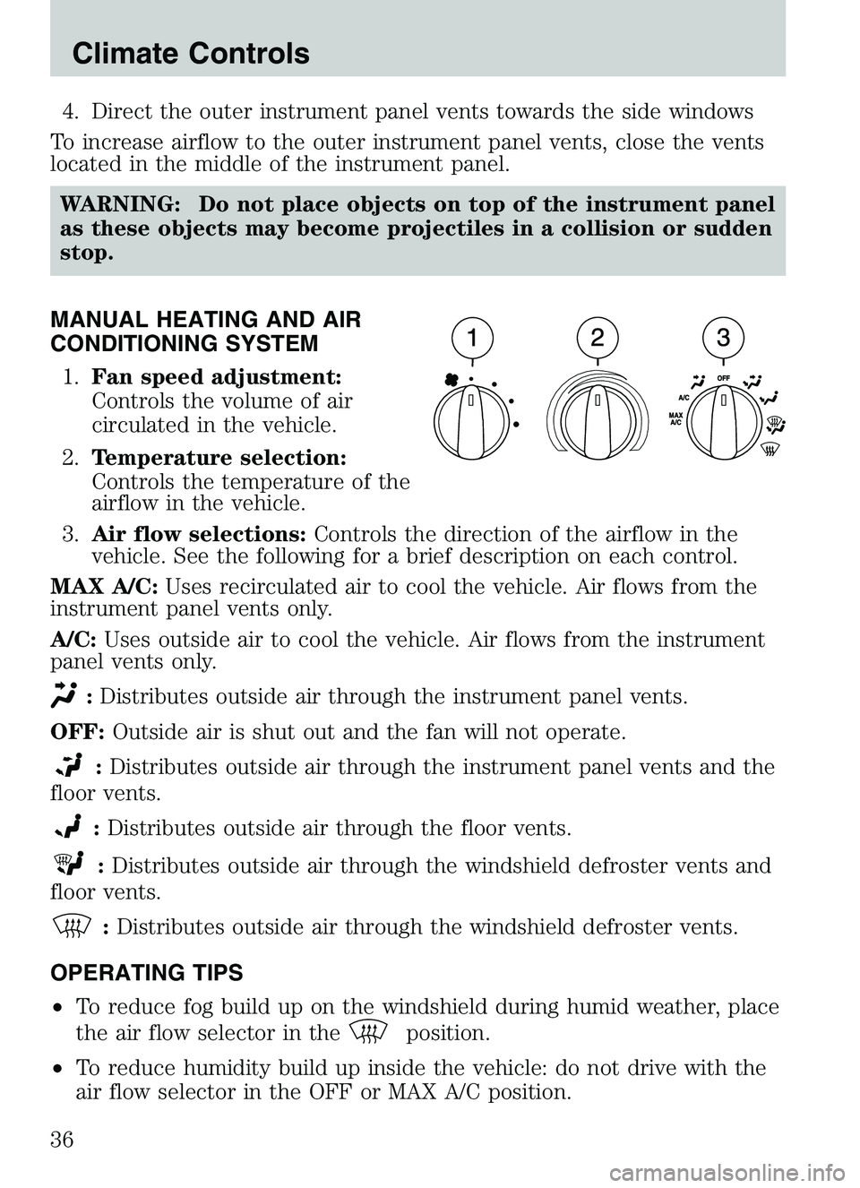
MANUAL HEATING AND AIR
CONDITIONING SYSTEM 1. Fan speed adjustment:
Controls the volume of air
circulated in the vehicle.
2. Temperature selection:
Controls the temperature of the
airflow in the vehicle.
3. Air flow selections: Controls the direction of the airflow in the
vehicle. See the following for a brief description on each control.
MAX A/C: Uses recirculated air to cool the vehicle. Air flows from the
instrument panel vents only.
A/C: Uses outside air to cool the vehicle. Air flows from the instrument
panel vents only.
: Distributes outside air through the instrument panel vents.
OFF: Outside air is shut out and the fan will not operate.
:Distributes outside air through the instrument panel vents and the
floor vents.
: Distributes outside air through the floor vents.
:Distributes outside air through the windshield defroster vents and
floor vents.
: Distributes outside air through the windshield defroster vents.
OPERATING TIPS
• To reduce fog build up on the windshield during humid weather, place
the air flow selector in the
position.
• To reduce humidity build up inside the vehicle: do not drive with the
air flow selector in the OFF or MAX A/C position.
Climate Controls
36
Page 37 of 250
•Under normal weather conditions, do not leave the air flow selector in
MAX A/C or OFF when the vehicle is parked. This allows the vehicle
to “breathe” using the outside air inlet vents.
• Do not put objects under the front seats that will interfere with the
airflow to the back seats.
• Remove any snow, ice or leaves from the air intake area at the base of
the windshield.
To aid in side window defogging/demisting in cold weather:
1. Select
2. Select A/C
3. Modulate the temperature control to maintain comfort.
4. Set the fan speed to HI
5. Direct the outer instrument panel vents towards the side windows
To increase airflow to the outer instrument panel vents, close the vents
located in the middle of the instrument panel.
WARNING: Do not place objects on top of the instrument panel
as these objects may become projectiles in a collision or sudden
stop.
Climate Controls
37
Page 50 of 250

One touch down
Allows the driver’s window to open
fully without holding the control
down. Press completely down on
AUTO and release quickly. Press
again to stop.
AUTOMATIC DIMMING REAR VIEW MIRRORS (IF EQUIPPED)
The electronic day/night mirror will change from the normal state to the
non-glare state when bright lights (glare) reach the inside rear view
mirror. When the inside rear view mirror detects bright light from behind
the vehicle, the inside rear view mirror will automatically adjust (darken)
to minimize glare.
Do not block the sensor on the backside of the inside rear view mirror
since this may impair proper system performance.
Press the left button on the mirror
to turn the auto dimming ON or
OFF. The green indicator light left
of the display will illuminate when
this feature is ON.
COMPASS/TEMPERATURE EC MIRROR (IF EQUIPPED)
The compass reading may be affected when you drive near large
buildings, bridges, power lines and powerful broadcast antennas.
Magnetic or metallic objects placed in, on or near the vehicle may also
affect compass accuracy.
Usually, when something affects the compass readings, the compass will
correct itself after a few days of operating your vehicle in normal
conditions. If the compass still appears to be inaccurate, a manual
calibration may be necessary. Refer toCompass calibration
adjustment.
Most geographic areas (zones) have a magnetic north compass point that
varies slightly from the northerly direction on maps. This variation is four
Driver Controls
50
Page 73 of 250
WARNING: BELT AND RETRACTOR ASSEMBLY MUST BE
REPLACED if the seat belt assembly “automatic locking
retractor” feature or any other seat belt function is not
operating properly when checked according to the procedures in
Workshop Manual.
WARNING: Failure to replace the Belt and Retractor assembly
could increase the risk of injury in collisions.
Safety belt pretensioner
Your vehicle is equipped with safety belt pretensioners at the driver and
front outboard passenger seating positions. Both pretensioners will fire if
the front airbags fire, whether or not there is a belted occupant in either
front outboard seat.
The safety belt pretensioners are designed to activate during certain
frontal or near-frontal collisions with sufficient longitudinal deceleration.
A safety belt pretensioner is a device which tightens the webbing of the
lap and shoulder belts in such a way that they fit more snugly against
the body.
The driver and front outboard passenger safety belt system (including
retractors, buckle assembly, pretensioner assembly with seat and height
adjusters) must be replaced if the vehicle is involved in a collision that
results in the activation of the safety belt pretensioners. Refer to the
Safety belt maintenance section in this chapter.
WARNING: Failure to replace the safety belt assembly under
the above conditions could result in severe personal injuries in
the event of a collision.
Front safety belt height adjustment
Your vehicle has safety belt height adjustments for the driver and front
passenger. Adjust the height of the shoulder belt so the belt rests across
the middle of your shoulder.
Seating and Safety Restraints
73
Page 81 of 250

The energy absorbing functions may have been activated in a collision so
the restraints should be examined; if the front air bags have deployed,
the pretensioners have also deployed and must be replaced — regardless
of whether there was an occupant in the passenger seat or not.WARNING: Failure to inspect and if necessary replace the
safety belt assembly under the above conditions could result in
severe personal injuries in the event of a collision.
Refer to Interior in theCleaning chapter.
AIR BAG SUPPLEMENTAL RESTRAINT SYSTEM (SRS)
Important supplemental restraint system (SRS) precautions
The supplemental restraint system is designed to work with the safety
belt to help protect the driver and right front passenger from certain
upper body injuries.
WARNING: Air bags DO NOT
inflate slowly or gently and the
risk of injury from a deploying
air bag is greatest close to the
trim covering the air bag
module. Always wear your
safety belt.
Seating and Safety Restraints
81
Page 87 of 250

•and the electrical wiring which connects the components.
The RCM (restraints control module) monitors its own internal circuits
and the supplemental air bag electrical system warning (including the
passenger air bag deactivation switch, the system wiring, the air bag
system readiness light, the air bag back up power and the air bag
ignitors).
Determining if the system is operational
The SRS uses readiness lights in the instrument cluster and the
passenger air bag deactivate switch or a tone to indicate the condition of
the system. Refer to the Air bag readinesssection in the
Instrumentation chapter orPassenger air bag deactivate switch
section in this chapter. Routine maintenance of the air bag is not
required.
A difficulty with the system is indicated by one or more of the following:
• The readiness lights will either
flash or stay lit.
• The readiness lights will not
illuminate immediately after
ignition is turned on.
• A series of five beeps will be heard. The tone pattern will repeat
periodically until the problem and/or light are repaired.
If any of these things happen, even intermittently, have the SRS serviced
at your authorized Mazda dealership immediately.
WARNING: Unless serviced, the system may not function
properly in the event of a collision.
Disposal of air bags and air bag equipped vehicles (including
safety belt pretensioners)
For disposal of safety belt pretensioners, air bags, or air bag equipped
vehicles, see your authorized Mazda dealership or qualified technician.
Air bags MUST BE disposed of by qualified personnel.
Seating and Safety Restraints
87