AUX MAZDA MODEL B4000 4WD 2002 Owners Manual
[x] Cancel search | Manufacturer: MAZDA, Model Year: 2002, Model line: MODEL B4000 4WD, Model: MAZDA MODEL B4000 4WD 2002Pages: 288, PDF Size: 1.87 MB
Page 11 of 288

4X4
HIGH
2WD 4X4
LOW
OFF
ON
OFF
OFF
PASSENGER AIRBAG
1234AM/FM
SEEKTONECLKTUNETONE VOL
12 FMSTDXVOL
PUSH ON
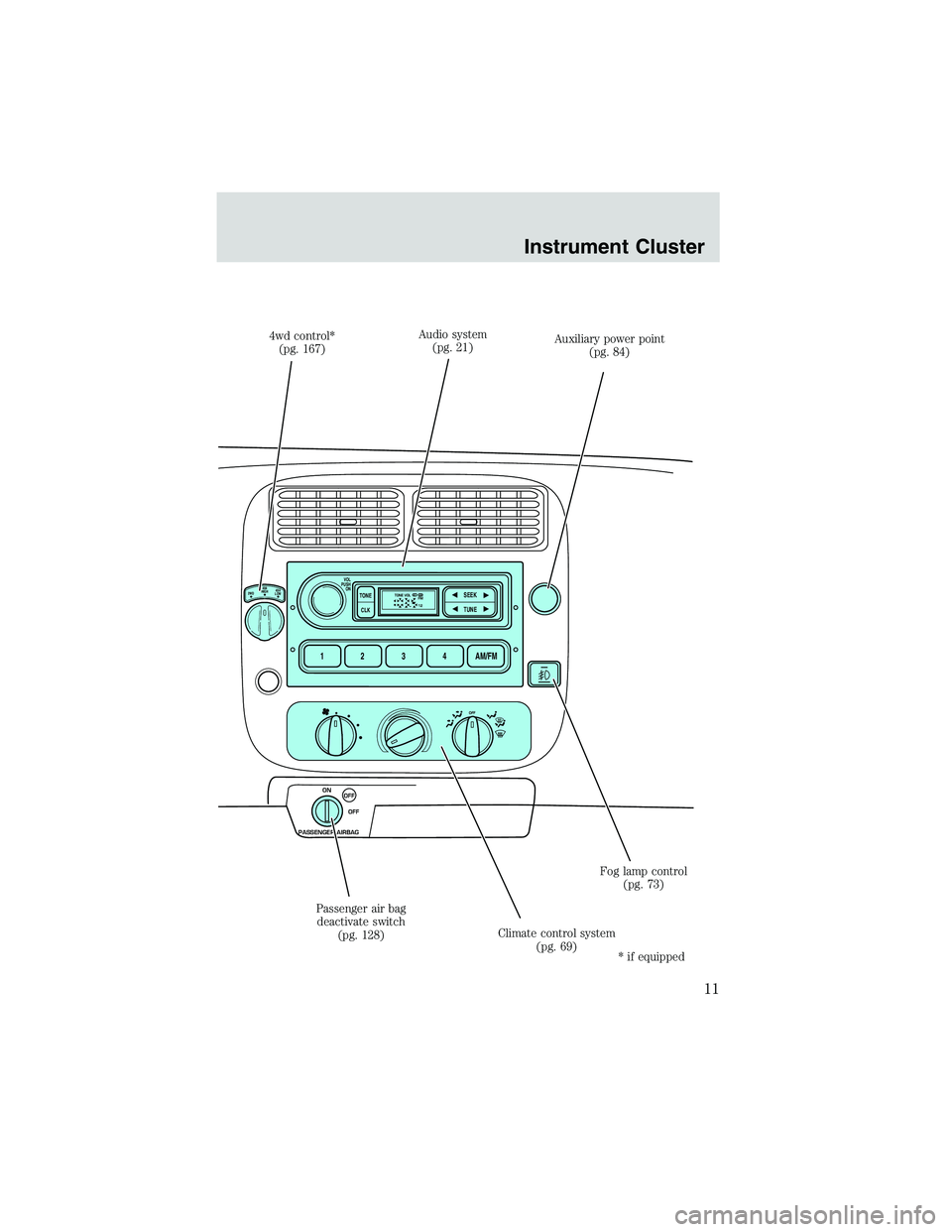
4wd control*
(pg. 167) Audio system
(pg. 21) Auxiliary power point
(pg. 84)
Fog lamp control (pg. 73)
Climate control system (pg. 69)
Passenger air bag
deactivate switch (pg. 128)
* if equipped
Instrument Cluster
11
Page 84 of 288

WARNING: Never adjust the steering wheel when the vehicle is
moving. You could lose control of the vehicle.
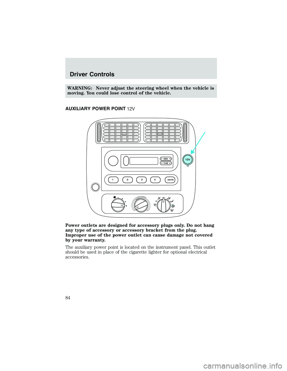
AUXILIARY POWER POINT
Power outlets are designed for accessory plugs only. Do not hang
any type of accessory or accessory bracket from the plug.
Improper use of the power outlet can cause damage not covered
by your warranty.
The auxiliary power point is located on the instrument panel. This outlet
should be used in place of the cigarette lighter for optional electrical
accessories.
OFFA/CMAX A/C
TUNESEEK12V
1
2
34AM-FM
Driver Controls
84
Page 187 of 288

Fuse/RelayLocation Fuse Amp
Rating Passenger Compartment Fuse
Panel Description
18 — Not used
19 25A Powertrain Control Module (PCM)
power diode, Ignition, PATS
20 7.5A GEM, Radio
21 15A Hazard flasher
22 20A Auxiliary power socket
23 — Not used
24 7.5A Clutch Pedal Position (CPP)
switch, Starter interrupt relay
25 — Not used
26 10A Battery saver relay, Auxiliary relay
box, Restraint Central Module
(RCM), GEM, Instrument cluster
27 — Not used
28 7.5A GEM, Radio
29 20A Radio
30 — Not used
31 — Not used
32 — Not used
33 15A Headlamps, Daytime Running
Lamps (DRL) module, Instrument
cluster
34 — Not used
35 15A Horn relay (if not equipped with a
CSM)
36 — Not used
Roadside Emergencies
187
Page 190 of 288

Fuse/RelayLocation Fuse Amp
Rating Power Distribution Box
Description
13 — Not used
14 — Not used
15 — Not used
16 40A** Blower motor
17 20A** Auxiliary cooling fan
18 — Not used
19 — Not used
20 — Not used
21 10A* PCM memory
22 — Not used
23 20A* Fuel pump motor
24 30A* Headlamps
25 10A* A/C clutch relay
26 — Not used
27 — Not used
28 30A* ABS module
29 — Not used
30 15A* Trailer Tow
31 20A* Foglamp, Daytime Running Lamps
(DRL)
32 — Not used
33 15A* Park lamp, Central security
module
34 — Not used
35 — Not used
36 — Not used
37 — Not used
38 10A* Left headlamp low beam
39 — Not used
40 — Not used
41 20A* Heated oxygen sensors
Roadside Emergencies
190
Page 191 of 288

Fuse/RelayLocation Fuse Amp
Rating Power Distribution Box
Description
42 10A* Right headlamp low beam
43 — (Resistor)
44 — Not used
45A — Wiper HI/LO relay
45B — Wiper park/run relay
46A — Fuel pump relay
46B — Trailer tow relay
47 — Starter relay
48 — Auxiliary cooling fan
49 — Not used
50 — Not used
51 — Not used
52 — Not used
53 — PCM Diode
54 — PCM Relay
55 — Blower motor relay
56A — A/C clutch relay
56B — Front washer pump relay
* Mini Fuses ** Maxi Fuses
Roadside Emergencies
191
Page 233 of 288

•Manual transmission:
1. Set the parking brake.
2. Depress the clutch and place the gearshift in 1 (First).
3. Turn off the engine and remove the key.
4. Block the wheels to prevent the vehicle from moving unexpectedly.
Working with the engine on
• Automatic transmission:
1. Set the parking brake and ensure the gearshift is securely latched in P (Park).
2. Block the wheels to prevent the vehicle from moving unexpectedly.
Note: Do not start your engine with the air cleaner removed and do not
remove it while the engine is running.
• Manual transmission:
1. Set the parking brake, depress the clutch and place the gearshift in neutral.
2. Block the wheels to prevent the vehicle from moving unexpectedly.
Note: Do not start your engine with the air cleaner removed and do not
remove it while the engine is running.
WARNING: The cooling fan is automatic and may come on at
any time. Always disconnect the negative terminal of the
battery before working near the fan.
OPENING THE HOOD
1. Inside the vehicle, pull the hood release handle located under
the bottom of the instrument
panel near the steering column.
2. Go to the front of the vehicle and release the auxiliary latch
that is located under the front
center of the hood.
3. Lift the hood and support it with the prop rod.
Maintenance and Specifications
233
Page 280 of 288

A
ABS (see Brakes) .....................154
Air bag supplemental restraint
system ................................119–120and child safety seats ............122
description ..............................120
disposal ....................................126
driver air bag ..........................124
indicator light .............14–15, 125
operation .................................124
passenger air bag ...................124
passenger deactivation
switch ......................................126
Air conditioning manual heating and air
conditioning system .................69
Ambulance packages ....................7
Antifreeze (see Engine
coolant) .....................................245
Anti-lock brake system
(see Brakes) ......................154–155
Anti-theft system warning light .............................16
Audio system
(see Radio) ......................21, 45, 53
Automatic transmission ............158 driving an automatic
overdrive .................................159
fluid, adding ............................263
fluid, checking ........................263
fluid, refill capacities ..............272
fluid, specification ..................276
Auxiliary power point .................84
Axle lubricant specifications ..275–276
refill capacities ........................272
traction lok ..............................157
B
Battery .......................................243 acid, treating emergencies .....243
charging system warning
light ............................................15
jumping a disabled battery ....201
maintenance-free ....................243
servicing ..................................243
voltage gauge ............................19
Bed extender ..............................95
BeltMinder .................................115
Brakes ........................................153 anti-lock ...........................154–155
anti-lock brake system (ABS)
warning light .....................14, 155
brake warning light ..................13
fluid, checking and adding ....262
fluid, refill capacities ..............272
fluid, specifications .........275–276
lubricant specifications ..275–276
parking ....................................155
shift interlock ..........................158
Break-in period .............................5
Bulbs ............................................75
C
Capacities for refilling fluids ....272
Cargo area shade ........................95
Cargo net .....................................95
CD-6 disc .....................................53
CD-single .....................................25
CD-single premium .....................45
Cell phone warning ...................279
Certification Label ....................278
Changing a tire .........................194
Child safety restraints ..............132 child safety belts ....................132
Child safety seats ......................135
Index
280