instrument panel MAZDA MODEL MX-30 EV 2022 Owners Manual
[x] Cancel search | Manufacturer: MAZDA, Model Year: 2022, Model line: MODEL MX-30 EV, Model: MAZDA MODEL MX-30 EV 2022Pages: 547, PDF Size: 79.35 MB
Page 69 of 547

Supplemental Restraint
System (SRS) Precautions
▼ Supplemental Restraint System
(SRS) Precautions
The front and side supplemental
restraint systems (SRS) include
different
types of air bags. Please verify the
di fferent types of air bags which are
equipped on your vehicle by locating
the “SRS AIRBAG” location indicators.
These indicators are visible in the area
where the air bags are installed.
The air bags are installed in the
following locations:
The steering wheel hub (driver air
bag)
The front passenger dashboard (front
passenger air bag)
Under the instrument panel (driver
and front passenger knee air bags)
The outboard sides of the front
seatbacks (side air bags)
The front and rear window pillars,
and the roof edge along both sides
(curtain air bags)
The air bag supplemental restraint
systems are designed to provide
supplemental protection in certain
situations so seat belts are always
important in the following ways:
Without seat belt usage, the air bags
cannot provide adequate protection
during an accident. Seat belt usage is
necessary to:
Keep the occupant from being
thrown into an inflating air bag.
Reduce the possibility of injuries
during an accident that is not
designed for air bag in
flation, such as
rear impact.
Reduce the possibility of injuries in
frontal, near frontal or side collisions
or roll-over accidents that are not
severe enough to activate the air
bags.
Reduce the possibility of being
thrown from your vehicle.
Reduce the possibility of injuries to
lower body and legs during an
accident.
Hold the driver in a position which
allows better control of the vehicle.
Refer to the Front Passenger Occupant
Classi fication System (page 2-64) for
details.
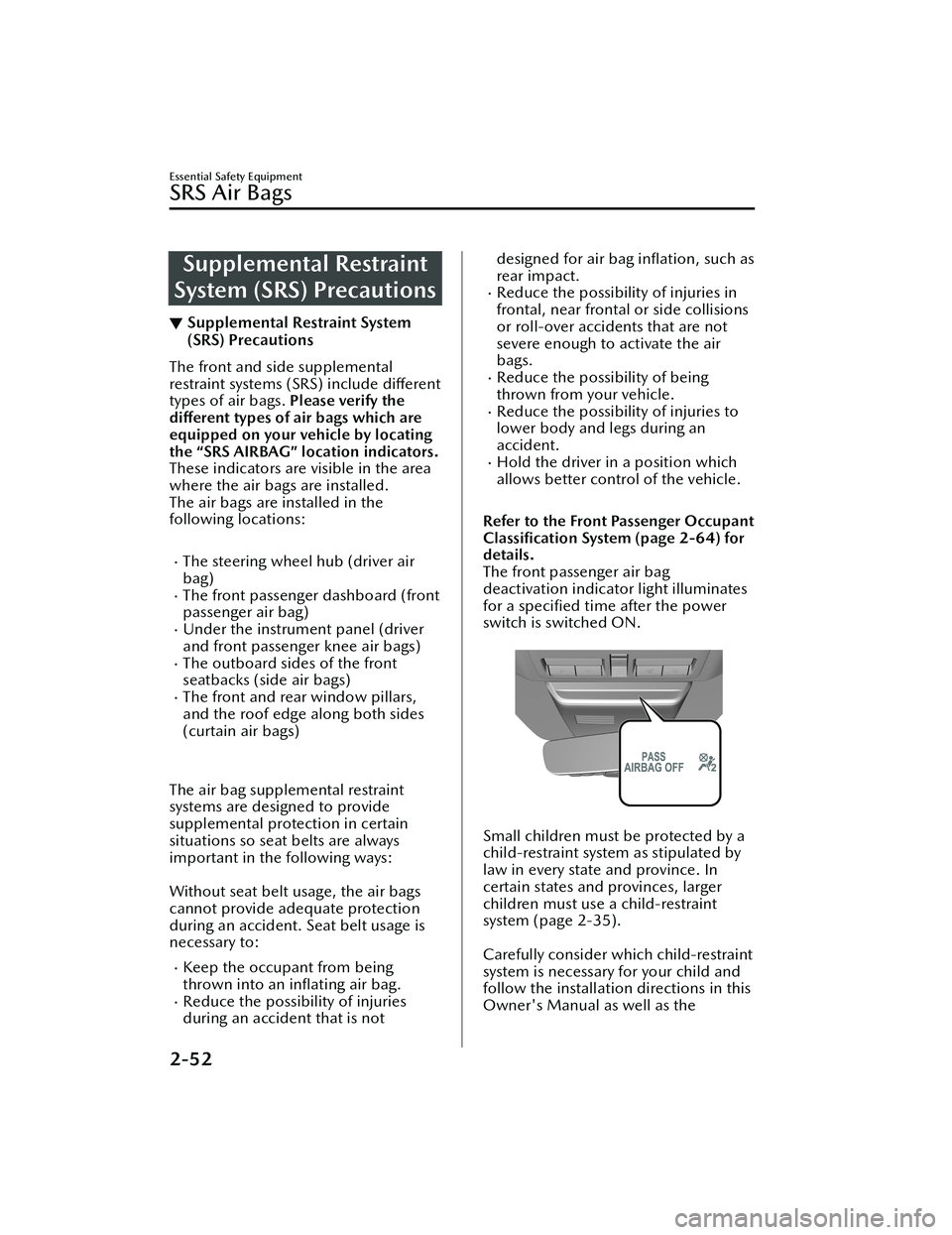
The front passenger air bag
deactivation indicator light illuminates
for a speci fied time after the power
switch is switched ON.
Small children must be protected by a
child-restraint system as stipulated by
law in every state and province. In
certain states and provinces, larger
children must use a child-restraint
system (page 2-35).
Carefully consider which child-restraint
system is necessary for your child and
follow the installation directions in this
Owner's Manual as well as the
Essential Safety Equipment
SRS Air Bags
2-52
MX -30_8JD4-EA -21G_Edition2_new 2021-5-18 14:38:07
Page 71 of 547

Sit in the center of the seat and wear
seat belts properly:
Sitting too close to the side air bag
modules or placing hands on them, or
sleeping up against the door or
hanging out the windows is extremely
dangerous. The side and curtain air
bags inflate with great force and speed
directly expanding along the door on
the side the car is hit. Serious injury
could occur if someone is sitting too
close to the door or leaning against a
window, or if rear seat occupants grab
the sides of the front seatbacks. Give
the side and curtain air bags room to
work by sitting in the center of the seat
while the vehicle is moving with seat
belts worn properly.
Do not attach objects on or around
the area where air bags deploy:
Attaching objects to the air bags or
placing something in the area where
the air bags deploy is dangerous. In an
accident, an object could interfere with
air bag in flation and injure the
occupants. Furthermore, the bag could
be damaged causing gases to release.
Always keep the deployment area of
the air bag modules free of any
obstructions.
For example, you should not do any of
the following as it may interfere with
air bag deployment.
Do not put a covering on or lean
anything against areas such as the
dashboard and lower portion of the
instrument panel that blocks the
passenger front air bag and knee air
bags.
Do not use seat covers on the front
seats and rear seats equipped with
in-seat side air bags.
Do not hang any backpacks, bags or
pouches that cover the sides of the
seats that block the side air bags.Do not place any objects on the
assist grips. Only hang clothes
directly on the coat hooks.
Do not touch the components of the
supplemental restraint system after
the air bags have in flated:
Touching the components of the
supplemental restraint system after the
air bags have in flated is dangerous.
Immediately after inflation, they are
very hot. You could get burned.
Never install any front-end equipment
to your vehicle:
Installation of front-end equipment,
such as frontal protection bar
(kangaroo bar, bull bar, push bar, or
other similar devices), snowplow, or
winches, is dangerous. The air bag
crash sensor system could be a ffected.
This could cause air bags to inflate
unexpectedly, or it could prevent the
air bags from inflating during an
accident. Front occupants could be
seriously injured.
Do not modify the suspension:
Modifying the vehicle suspension is
dangerous. If the vehicle's height or
the suspension is modi fied, the vehicle
will be unable to accurately detect a
collision or roll-over accident resulting
in incorrect or unexpected air bag
deployment and the possibility of
serious injuries.
To prevent false detection by the air
bag sensor system, heed the
following:
Do not use tires or wheels other than
those
specified for your Mazda:
Essential Safety Equipment
SRS Air Bags
2-54
MX
-30_8JD4-EA -21G_Edition2_new 2021-5-18 14:38:07
Page 75 of 547

How the SRS Air BagsWork
▼How the SRS Air Bags Work
Your Mazda is equipped with the
following types of SRS air bags. SRS air
bags are designed to work together
with the seat belts to help to reduce
injuries during an accident.
The SRS air bags are designed to
provide further protection for
passengers in addition to the seat belt
functions. Be sure to wear seat belts
properly.
▼Front Seat Belt Pretensioners
The front seat belt pretensioners are
designed to deploy in moderate or
severe frontal, near frontal collisions.
In addition, the pretensioners operate
when a side collision or a roll-over
accident is detected. The pretensioners
operate
differently depending on what
types of air bags are equipped. For
more details about seat belt
pretensioner operation, refer to the
SRS Air Bag Deployment Criteria (page
2-61).
▼ Driver Air Bag
The driver's air bag is mounted in the
steering wheel.
When air bag crash sensors detect a
frontal impact of greater than
moderate force, the driver's air bag
in
flates quickly helping to reduce injury
mainly to the driver's head or chest
caused by directly hitting the steering
wheel.
For more details about air bag
deployment, refer to "SRS Air Bag
Deployment Criteria" (page 2-61).
The driver's dual-stage air bag controls
air bag in flation in two energy stages.
During an impact of moderate severity,
the driver's air bag deploys with lesser
energy, whereas during more severe
impacts, it deploys with more energy.
▼ Front Passenger Air Bag
The front passenger air bag is mounted
in the front passenger dashboard.
The
inflation mechanism for the front
passenger air bag is the same as the
driver's air bag.
For more details about air bag
deployment, refer to "SRS Air Bag
Deployment Criteria" (page 2-61).
In addition, the front passenger air bag
is designed to only deploy in
accordance with the total seated
weight on the front passenger seat. For
details, refer to the driver and front
passenger occupant classi fication
system (page 2-64).
▼ Driver and Front Passenger Knee
Air Bags
The knee air bags are equipped under
the instrument panel.
Essential Safety Equipment
SRS Air Bags
2-58
MX
-30_8JD4-EA -21G_Edition2_new 2021-5-18 14:38:07
Page 163 of 547

NOTE
When the high voltage battery
temperature is high or low, the output
may be restricted to protect the EV
system.
▼High Voltage Battery Power Gauge
The remaining power of the high
voltage battery is indicated when the
power switch is switched ON.
When the high voltage battery is fully
charged, F is indicated. As the level
lowers, the needle approaches E.
When the high voltage battery charge
decreases to 1/4 or lower, we
recommend charging the battery.
1. F (Fully charged)
2. 1/4 charged
3. E (Fully discharged)
When the remaining charge of the high
voltage battery is low, output may be
restricted. If the output is restricted,
charge the battery as soon as possible.
NOTE
After charging, it may require some
time for the needle to stabilize.
The arrow indicates that the
charging port is on the right side.
▼ Dashboard Illumination
When the lights are turned on with the
power switch switched ON, the
brightness of the dashboard
illumination is dimmed. However,
when the light sensor detects that the
surrounding area is bright such as
when the lights are turned on in the
daytime, the dashboard illumination
does not dim.
NOTE
When the power switch is switched
ON in the early evening or at dusk,
the dashboard illumination is
dimmed for several seconds until the
light sensor detects the brightness of
the surrounding area, however, the
dimming may cancel after the
brightness is detected.
When the lights are turned on, the
lights-on indicator light in the
instrument cluster turns on.
Refer to Headlights on page 4-35.
The brightness of the instrument panel
and dashboard illuminations can be
adjusted by pressing the dashboard
illumination switch while the
dashboard illumination is dimmed.
The brightness increases by pressing
the + switch.
The brightness decreases by pressing
the - switch. If you press the - switch
while the instrument cluster is at
maximum dimness, a sound is
activated to notify you that the
When Driving
Instrument Cluster and Display
4-14
MX -30_8JD4-EA -21G_Edition2_new 2021-5-18 14:38:07
Page 405 of 547

Scheduled Maintenance
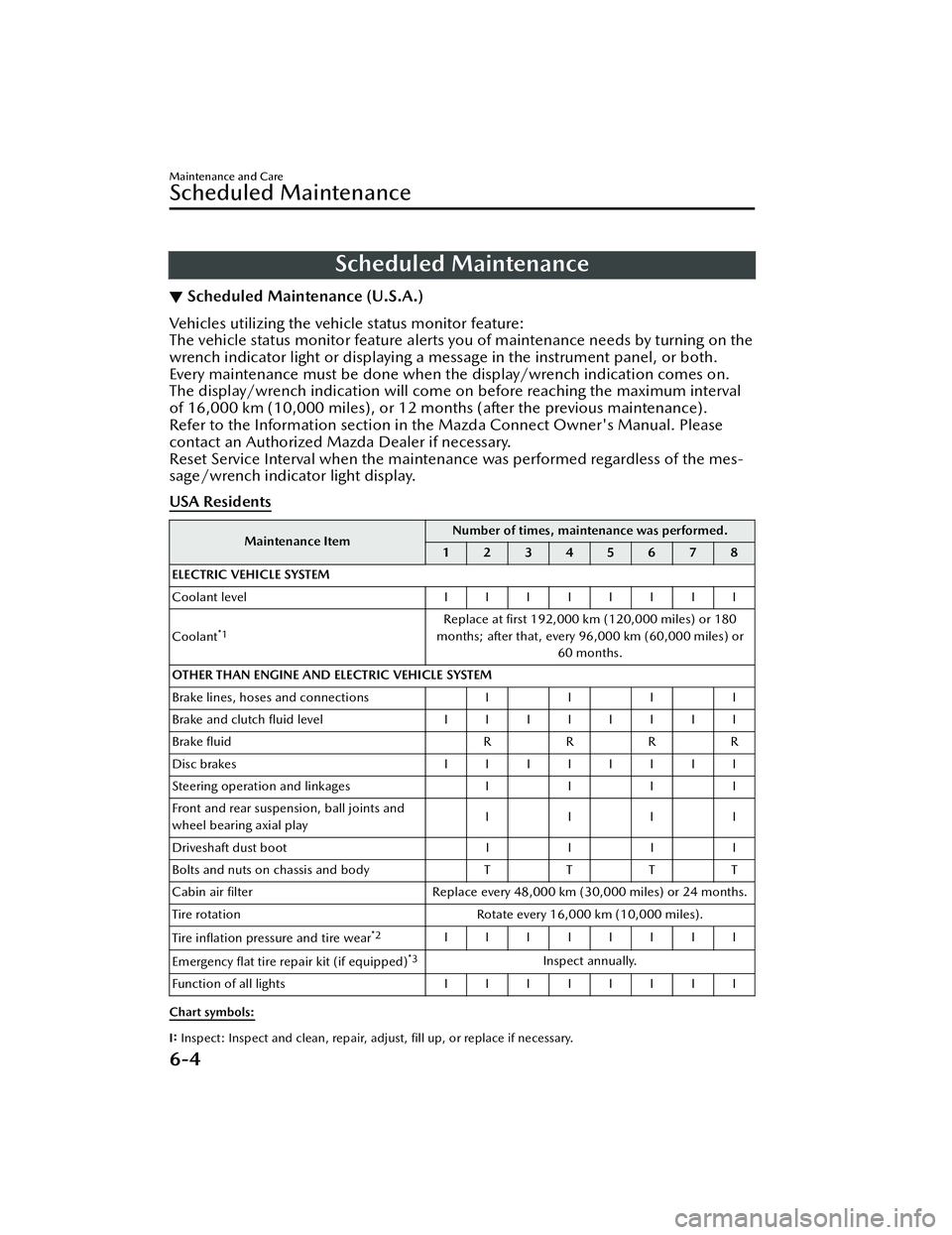
▼Scheduled Maintenance (U.S.A.)
Vehicles utilizing the vehicle status monitor feature:
The vehicle status monitor feature alerts you of maintenance needs by turning on the
wrench indicator light or displaying a message in the instrument panel, or both.
Every maintenance must be done when the display/wrench indication comes on.
The display/wrench indication will come
on before reaching the maximum interval
of 16,000 km (10,000 miles), or 12 mont hs (after the previous maintenance).
Refer to the Information section in the Mazda Connect Owner's Manual. Please
contact an Authorized Mazda Dealer if necessary.
Reset Service Interval when the maintenance was performed regardless of the mes-
sage/wrench indicator light display.
USA Residents
Maintenance Item Number of times, maintenance was performed.
12345678
ELECTRIC VEHICLE SYSTEM
Coolant level IIIIIIII
Coolant
*1Replace at first 192,000 km (120,000 miles) or 180
months; after that, every 96,000 km (60,000 miles) or 60 months.
OTHER THAN ENGINE AND ELECTRIC VEHICLE SYSTEM
Brake lines, hoses and connections I I I I
Brake and clutch fl uid level IIIIIIII
Brake fluid RRR R
Disc brakes IIIIIIII
Steering operation and linkages III I
Front and rear suspension, ball joints and
wheel bearing axial play IIII
Driveshaft dust boot III I
Bolts and nuts on chassis and body TT TT
Cabin air filter Replace every 48,000 km (30,000 miles) or 24 months.
Tire rotation Rotate every 16,000 km (10,000 miles).
Tire in flation pressure and tire wear
*2IIIIIIII
Emergency flat tire repair kit (if equipped)
*3Inspect annually.
Function of all lights IIIIIIII
Chart symbols:
I: Inspect: Inspect and clean, repair, adjust, fill up, or replace if necessary.
Maintenance and Care
Scheduled Maintenance
6-4
MX -30_8JD4-EA -21G_Edition2_new 2021-5-18 14:38:07
Page 406 of 547

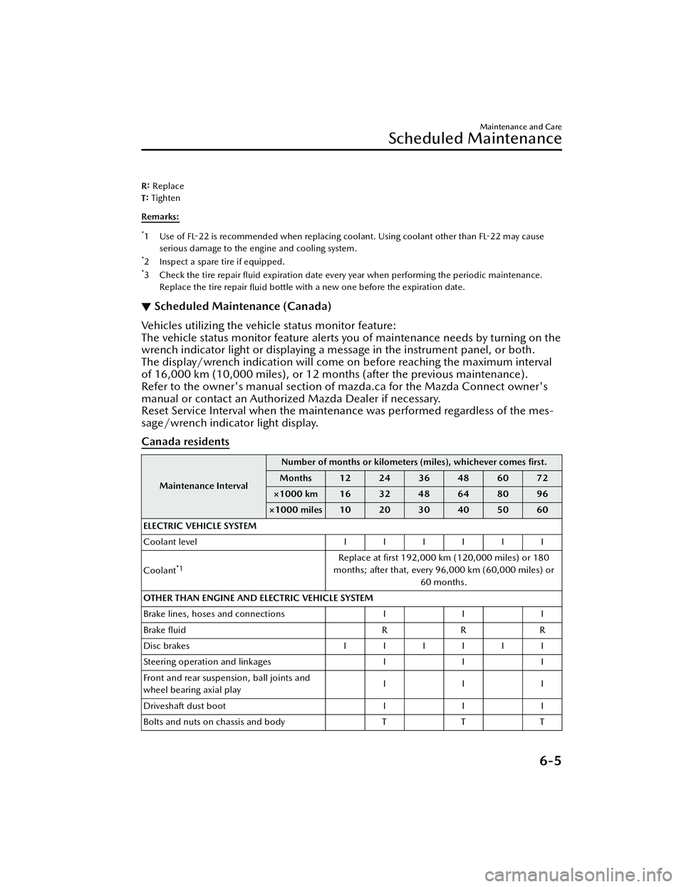
R: Replace
T: Tighten
Remarks:
*1Use of FL-22 is recommended when replacing coolant. Using coolant other than
FL-22 may cause
serious damage to the engine and cooling system.
*2 Inspect a spare tire if equipped.*3Check the tire repair fl uid expiration date every year when performing the periodic maintenance.
Replace the tire repair fluid bottle with a new one before the expiration date.
▼Scheduled Maintenance (Canada)
Vehicles utilizing the vehicle status monitor feature:
The vehicle status monitor feature alerts you of maintenance needs by turning on the
wrench indicator light or displaying a message in the instrument panel, or both.
The display/wrench indication will come on before reaching the maximum interval
of 16,000 km (10,000 miles), or 12 mont
hs (after the previous maintenance).
Refer to the owner's manual section of mazda.ca for the Mazda Connect owner's
manual or contact an Authorized Mazda Dealer if necessary.
Reset Service Interval when the maintena nce was performed regardless of the mes-
sage/wrench indicator light display.
Canada residents
Maintenance Interval Number of months or kilomete
rs (miles), whichever comes first.
Months 12 24 36 48 60 72
×1000 km 16 32 48 64 80 96
×1000 miles 10 20 30 40 50 60
ELECTRIC VEHICLE SYSTEM
Coolant level IIIIII
Coolant
*1Replace at first 192,000 km (120,000 miles) or 180
months; after that, every 96,000 km (60,000 miles) or 60 months.
OTHER THAN ENGINE AND ELECTRIC VEHICLE SYSTEM
Brake lines, hoses and connections I I I
Brake fluid RRR
Disc brakes IIIIII
Steering operation and linkages I I I
Front and rear suspension, ball joints and
wheel bearing axial play III
Driveshaft dust boot I I I
Bolts and nuts on chassis and body T T T
Maintenance and Care
Scheduled Maintenance
6-5
MX -30_8JD4-EA -21G_Edition2_new 2021-5-18 14:38:07
Page 442 of 547

2. Wipe off the remaining detergent
using a cloth soaked in clean water
and wrung out well.
Synthetic leather
1. Remove dust and sand using a vacuum cleaner.
2. Wipe the soiled area with a soft cloth soaked in a mild detergent
(approx. 5%) diluted with water.
3. Wipe off the remaining detergent
using a cloth soaked in clean water
and wrung out well.
▼ Leather Upholstery Maintenance*
1. Remove dust and sand using a
vacuum cleaner.
2. Wipe off the soiled area with a soft
cloth and a suitable, special cleaner
or a soft cloth soaked in a mild
detergent (about 5%) diluted with
water.
3. Wipe off the remaining detergent
using a cloth soaked in clean water
and wrung out well.
4. Remove moisture with a dry, soft cloth and allow the leather to
further dry in a well-ventilated,
shaded area. If the leather gets wet
such as from rain, remove the
moisture and dry it as soon as
possible.
NOTE
Because genuine leather is a natural
material, its surface is not uniform
and it may have natural scars,
scratches, and wrinkles.
To maintain the quality for as long as
possible, periodical maintenance,
about twice a year, is recommended.
If the leather upholstery comes into
contact with any of the following,
clean it immediately.
Leaving it uncleaned could cause
premature wear, mold, or stains.
Sand or dirtGrease or oil, such as hand creamAlcohol, such as in cosmetic or
hair dressing items
If the leather upholstery gets wet,
promptly remove moisture with a dry
cloth. Remaining moisture on the
surface may cause deterioration such
as hardening and shrinkage.
Exposure to direct sunlight for long
periods may cause deterioration and
shrinkage. When parking the car
under direct sunlight for long
periods, shade the interior using
sunshades.
Do not leave vinyl products on the
leather upholstery for long periods.
They may a ffect the leather quality
and coloring. If the cabin
temperature becomes hot, the vinyl
may deteriorate and adhere to the
genuine leather.
▼ Plastic Part Maintenance
CAUTION
Do not use polishing agents.
Depending on the product ingredients,
they could cause discoloration, stains,
cracks or peeling of the coating.
▼
Instrument Panel Top (Soft pad)
Maintenance
Extremely soft materi
al is used for the
soft pad surface. If the soft pad surface
is rubbed harshly with a dry cloth, it
could result in the surface being
damaged and leaving white scratch
marks.
1. Wipe the soiled area with a soft cloth soaked in a mild detergent
(approx. 5%) diluted with water.
2. Wipe o ff the remaining detergent
using a cloth soaked in clean water
and wrung out well.
Maintenance and Care
Appearance Care
*Some models.6-41
MX -30_8JD4-EA -21G_Edition2_new 2021-5-18 14:38:07
Page 541 of 547

Index
Starting the EV System............ 4-5
Starting the EV System When the
Key Battery is Dead................ 4-6
When Stopping the EV
System................................... 4-8
Excessive Speed Warning........... 7-40
Exterior Care............................. 6-34 Aluminum wheel
maintenance........................ 6-39
Bright-metal maintenance..... 6-38
Camera and Lens
Maintenance........................ 6-38
Maintaining the finish........... 6-35
Plastic part maintenance....... 6-39
F
Flasher Hazard warning.................... 4-47
Headlights............................4-35
Flat Tire...................................... 7-3
Floor Mat................................. 3-57
Fluids Brake................................... 6-12
Classi fication.......................... 9-4
Washer................................ 6-13
Foot Brake................................ 4-52
Forward Sensing Camera (FSC)... 4-71
Front Camera/Side Cameras/Rear
Camera.................................... 4-81
Front Cross Tra ffic Alert (FCTA) ..........
.............................................. 4-104
Front Cross Tra ffic Alert (FCTA)
Warning Beep........................... 7-40
Front Radar Sensor.................... 4-75
Front Side Radar Sensor............. 4-77
Fully Discharged High Voltage Battery Actions to take if the remaining
high voltage battery power is
completely depleted............. 7-16
Fuses........................................ 6-27
Panel description.................. 6-29
Replacement........................ 6-27
G
Gauges....................................... 4-9
Glove Compartment..................5-45
H
Hazardous Driving.....................3-56
Hazard Warning Flasher............. 4-47
Headlights Coming home light...............4-37
Flashing................................4-37
High-low beam.................... 4-37
Leaving home light............... 4-37
Leveling................................4-38
Head Restraint.......................... 2-18
High Beam Control System
(HBC)....................................... 4-83 High Beam Control System (HBC)
indicator light (green)........... 4-83
High Voltage Battery.................... 9-3
Hill Launch Assist (HLA)............. 4-61
HomeLink Wireless Control
System...................................... 4-47
Hood Release............................. 6-8
Horn........................................ 4-46
I
If a Warning Light Turns On or
Flashes......................................7-21
If the Active Driving Display Does Not
Operate.................................... 7-43
Illuminated Entry System............ 5-38
Immobilizer System................... 3-54
Inspecting Brake Fl uid Level........6-12
Inspecting Coolan t Level............ 6-11
Inspecting Washer Fluid Level..... 6-13
Instrument Cluster.......................4-9 Average Energy E fficiency.......4-16
10-4
MX -30_8JD4-EA -21G_Edition2_new 2021-5-18 14:38:07
Page 542 of 547

Index
Compass display.................. 4-18
Dashboard illumination........ 4-14
Distance-to-full Discharge..... 4-16
High Voltage Battery Power
Gauge..................................4-14
High Voltage Battery Temperature
Gauge..................................4-13
Indication/indicator lights..... 4-21
Instantaneous Energy Efficiency .....
........................................... 4-17
i-ACTIVSENSE display........... 4-17
Message Display................... 4-18
Message indicated on multi-
information display............... 7-33
Multi-information display...... 4-11
Odometer............................ 4-13
Outside temperature
display................................. 4-15
Power Meter.......................... 4-9
Remaining High Voltage Battery
Power Indication.................. 4-16
Speedometer......................... 4-9
Trip meter............................ 4-13
Warning indication/warning
lights....................................4-19
Interior Care............................. 6-40 Active driving display
maintenance........................ 6-42
Cleaning the floor mats......... 6-42
Glass and Mirror
Maintenance........................ 6-42
Instrument panel top (Soft pad)
maintenance........................ 6-41
Leather upholstery
maintenance........................ 6-41
Panel and Cork Area
Maintenance........................ 6-42
Plastic part maintenance....... 6-41
Seat belt maintenance.......... 6-40
Upholstery and synthetic leather
maintenance........................ 6-40Vinyl upholstery
maintenance........................ 6-40
Interior Lights............................ 5-37 Luggage compartment light... 5-37
Map lights............................5-37
Overhead lights.................... 5-37
i-ACTIVSENSE........................... 4-68 Active safety technology........ 4-68
Adaptive Front Lighting System
(AFS)................................... 4-82
Blind Spot Monitoring
(BSM).................................. 4-87
Camera and sensors............. 4-69
Cruising & Traffic Support
(CTS)................................. 4-118
Distance & Speed Alert
(DSA).................................. 4-99
Driver Attention Alert
(DAA)................................ 4-100
Driver monitoring camera..... 4-81
Driver Monitoring (DM)...... 4-102
Emergency Lane Keeping
(ELK).................................. 4-129
Forward Sensing Camera
(FSC)................................... 4-71
Front camera/side cameras/rear
camera................................ 4-81
Front Cross Traffic Alert
(FCTA)............................... 4-104
Front radar sensor.................4-75
Front side radar sensor.......... 4-77
High Beam Control System
(HBC).................................. 4-83
i-ACTIVSENSE OFF Switch..... 4-70
i-ACTIVSENSE status symbol
(warning/risk avoidance support
system)................................ 4-69
Lane Departure Warning System
(LDWS)................................ 4-84
Lane-keep Assist System
(LAS)..................................4-127
10-5
MX -30_8JD4-EA -21G_Edition2_new 2021-5-18 14:38:07