ECU MAZDA MODEL RX 8 2010 (in English) Workshop Manual
[x] Cancel search | Manufacturer: MAZDA, Model Year: 2010, Model line: MODEL RX 8, Model: MAZDA MODEL RX 8 2010Pages: 438, PDF Size: 7.02 MB
Page 317 of 438

Black plate (317,1)
3. Install the lug nuts with the beveled
edge inward; tighten them by hand.
WARNING
Do not apply oil or grease to lug nuts
and bolts and do not tighten the lug
nuts beyond the recommended
tightening torque:
Applying oil or grease to lug nuts and
bolts is dangerous. The lug nuts
could loosen while driving and cause
the tire to come off, resulting in an
accident. In addition, lug nuts and
bolts could be damaged if tightened
more than necessary.
4. Turn the jack handle counterclockwise
and lower the vehicle. Use the lug
wrench to tighten the nuts in the order
shown.
If you're unsure of how tight the nuts
should be, have them inspected at an
Authorized Mazda Dealer.
Nut tightening torque
N·m (kgf·m, ft·lbf)88―118
(9―12, 65―87)
WARNING
Always securely and correctly tighten
the lug nuts:
Improperly or loosely tightened lug
nuts are dangerous. The wheel could
wobble or come off. This could result
in loss of vehicle control and cause a
serious accident.
Be sure to reinstall the same nuts you
removed or replace them with metric
nuts of the same configuration:
Because the wheel studs and lug nuts
on your Mazda have metric threads,
using a non-metric nut is dangerous.
On a metric stud, it would not secure
the wheel and would damage the
stud, which could cause the wheel to
slip off and cause an accident.
5. Check the inflation pressure. Refer to
the specification charts on page 10-6.
WARNING
Do not drive with any tires that have
incorrect air pressure:
Driving on tires with incorrect air
pressure is dangerous. Tires with
incorrect pressure could affect
handling and result in an accident.
In Case of an Emergency
Flat Tire
7-15
RX-8_8AT5-EA-09E_Edition1 Page317
Wednesday, April 15 2009 10:34 AM
Form No.8AT5-EA-09E
Page 324 of 438

Black plate (324,1)
3. Remove the battery cover from its rear
side.
4. Make sure the booster battery is 12 V
and that its negative terminal is
grounded.
5. If the booster battery is in another
vehicle, don't allow the vehicles to
touch. Turn off the engine of the
vehicle with the booster battery and all
unnecessary electrical loads in both
vehicles.
6. Connect the jumper cables in the exact
sequence as in the illustration.
lConnect one end of a cable to the
positive terminal on the discharged
battery (1).
lAttach the other end to the positive
terminal on the booster battery (2).
lConnect one end of the other cable
to the negative terminal of the
booster battery (3).
lConnect the other end to a solid,
stationary, exposed metallic point
(for example, the tightening bolt)
away from the discharged battery
(4).
Booster battery
Connect cables
in numerical
order and
disconnect in
reverse order.
Discharged
battery
7. Start the engine of the booster vehicle
and run it a few minutes. Then start the
engine of the other vehicle.
8. When finished, carefully disconnect the
cables in the reverse order described in
Step 6.
NOTE
Verify that the engine cover is securely
installed.
7-22
In Case of an Emergency
Emergency Starting
RX-8_8AT5-EA-09E_Edition1 Page324
Wednesday, April 15 2009 10:34 AM
Form No.8AT5-EA-09E
Page 327 of 438

Black plate (327,1)
Tiedown Hooks
CAUTION
Do not use the front and rear
tiedown eyelets for towing the
vehicle.
The have been designed only for
securing the vehicle to a transport
vessel during shipping.
Using the eyelets for any other
purpose could result in the vehicle
being damaged.
qTiedown Hooks
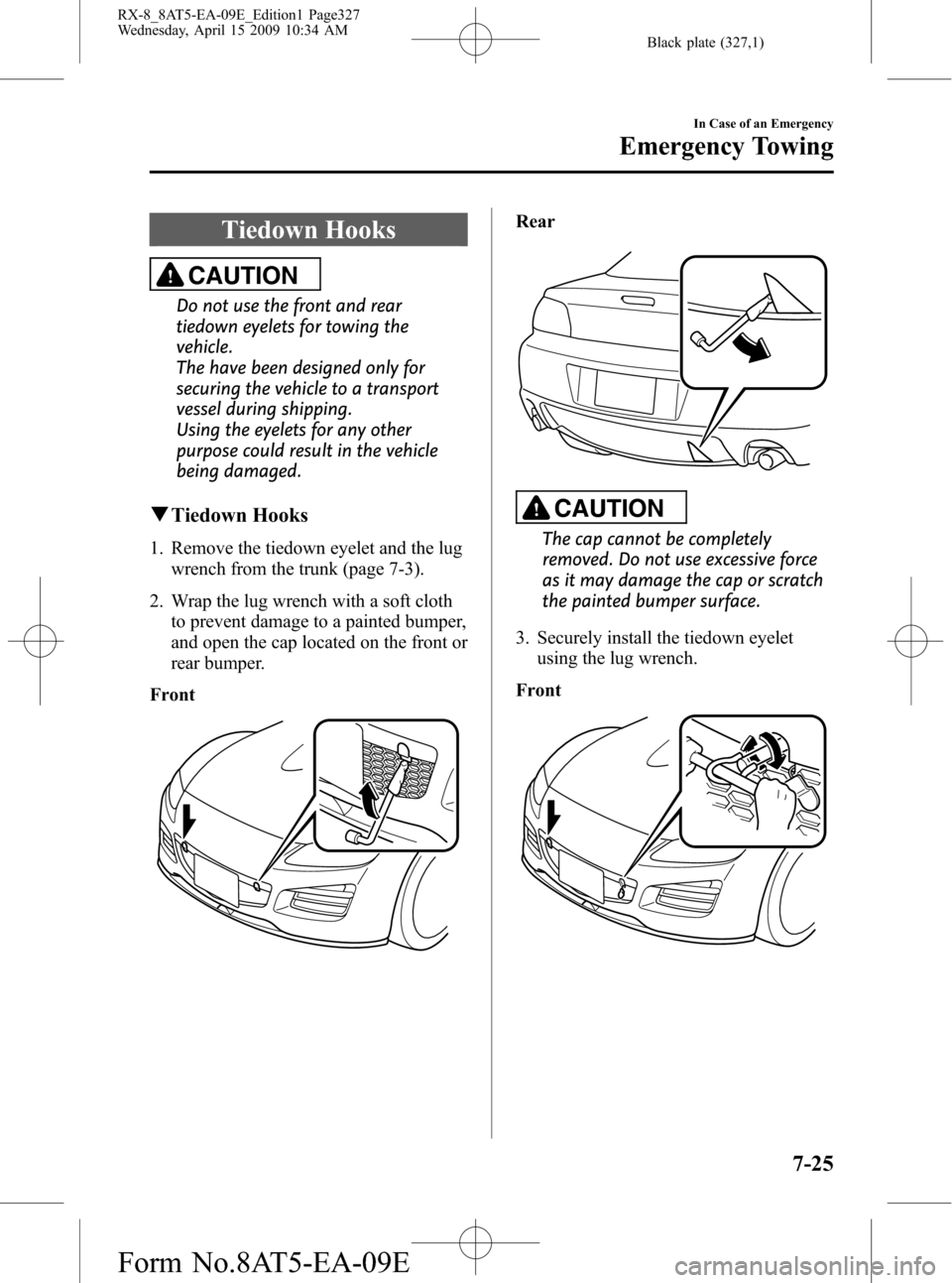
1. Remove the tiedown eyelet and the lug
wrench from the trunk (page 7-3).
2. Wrap the lug wrench with a soft cloth
to prevent damage to a painted bumper,
and open the cap located on the front or
rear bumper.
Front
Rear
CAUTION
The cap cannot be completely
removed. Do not use excessive force
as it may damage the cap or scratch
the painted bumper surface.
3. Securely install the tiedown eyelet
using the lug wrench.
Front
In Case of an Emergency
Emergency Towing
7-25
RX-8_8AT5-EA-09E_Edition1 Page327
Wednesday, April 15 2009 10:34 AM
Form No.8AT5-EA-09E
Page 328 of 438

Black plate (328,1)
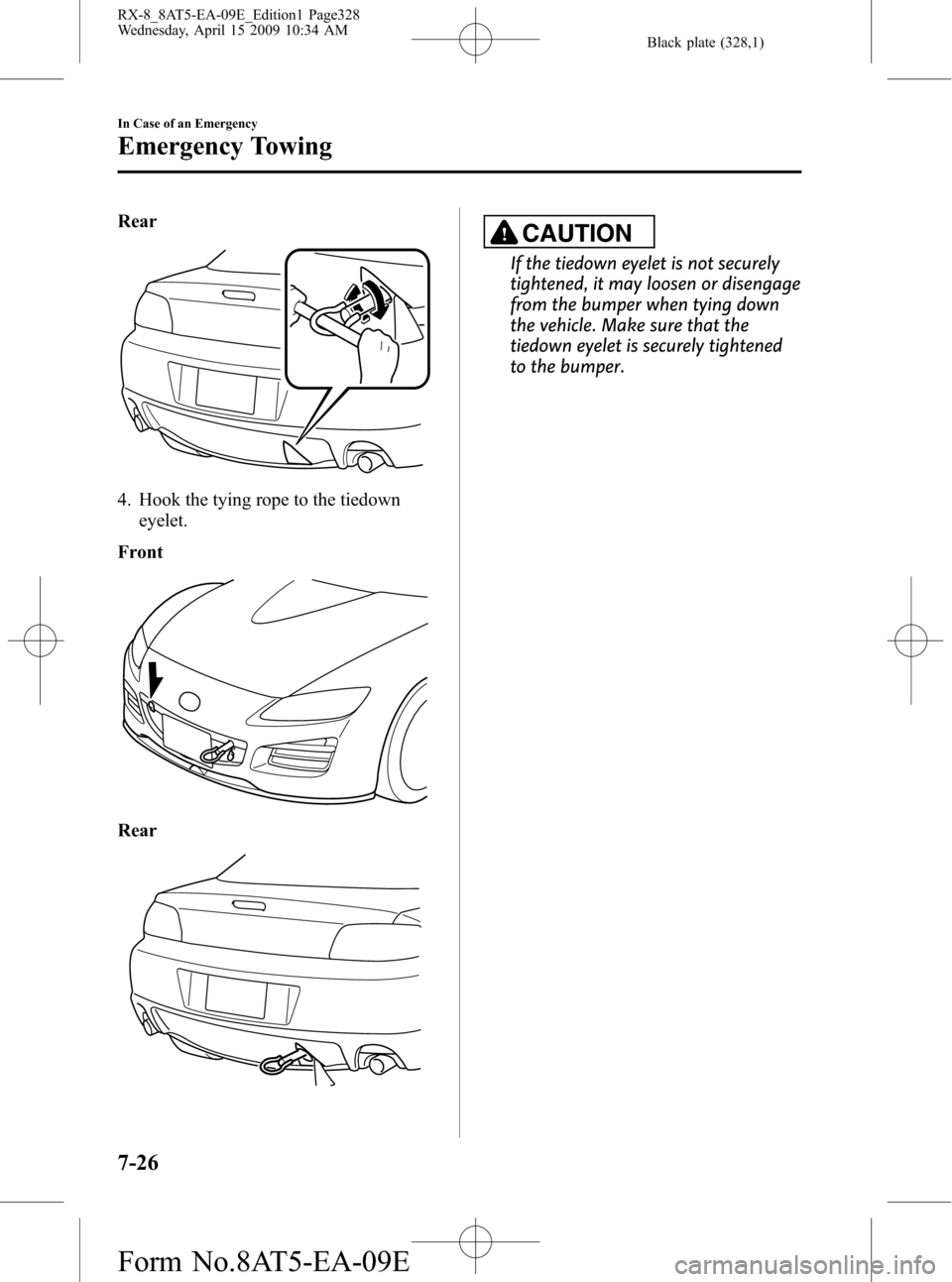
Rear
4. Hook the tying rope to the tiedown
eyelet.
Front
Rear
CAUTION
If the tiedown eyelet is not securely
tightened, it may loosen or disengage
from the bumper when tying down
the vehicle. Make sure that the
tiedown eyelet is securely tightened
to the bumper.
7-26
In Case of an Emergency
Emergency Towing
RX-8_8AT5-EA-09E_Edition1 Page328
Wednesday, April 15 2009 10:34 AM
Form No.8AT5-EA-09E
Page 344 of 438

Black plate (344,1)
NOTElEach mark from the Full mark equates to
about 0.5 L (0.5 US qt, 0.4 Imp qt).
There are 3 marks between Low and Full.
Full
Low
0.5 L (0.5 US qt, 0.4 Imp qt)
1.0 L (1.1 US qt, 0.9 Imp qt)
1.5 L (1.6 US qt, 1.3 Imp qt)
2.0 L (2.1 US qt, 1.8 Imp qt)
lVerify that the engine cover is securely
installed.
Engine Coolant
qInspecting Coolant Level
WARNING
Do not use a match or live flame in the
engine compartment. DO NOT ADD
COOLANT WHEN THE ENGINE IS HOT:
A hot engine is dangerous. If the
engine has been running, parts of the
engine compartment can become
very hot. You could be burned.
Carefully inspect the engine coolant
in the coolant reservoir, but do not
open it.
Turn off the ignition switch and
make sure the fan is not running before
attempting to work near the cooling
fan:
Working near the cooling fan when it
is running is dangerous. The fan
could continue running indefinitely
even if the engine has stopped and
the engine compartment temperature
is high. You could be hit by the fan
and seriously injured.
Do not remove the cooling
system cap when the engine and
radiator are hot:
When the engine and radiator are
hot, scalding coolant and steam may
shoot out under pressure and cause
serious injury.
8-14
Maintenance and Care
Owner Maintenance
RX-8_8AT5-EA-09E_Edition1 Page344
Wednesday, April 15 2009 10:34 AM
Form No.8AT5-EA-09E
Page 353 of 438

Black plate (353,1)
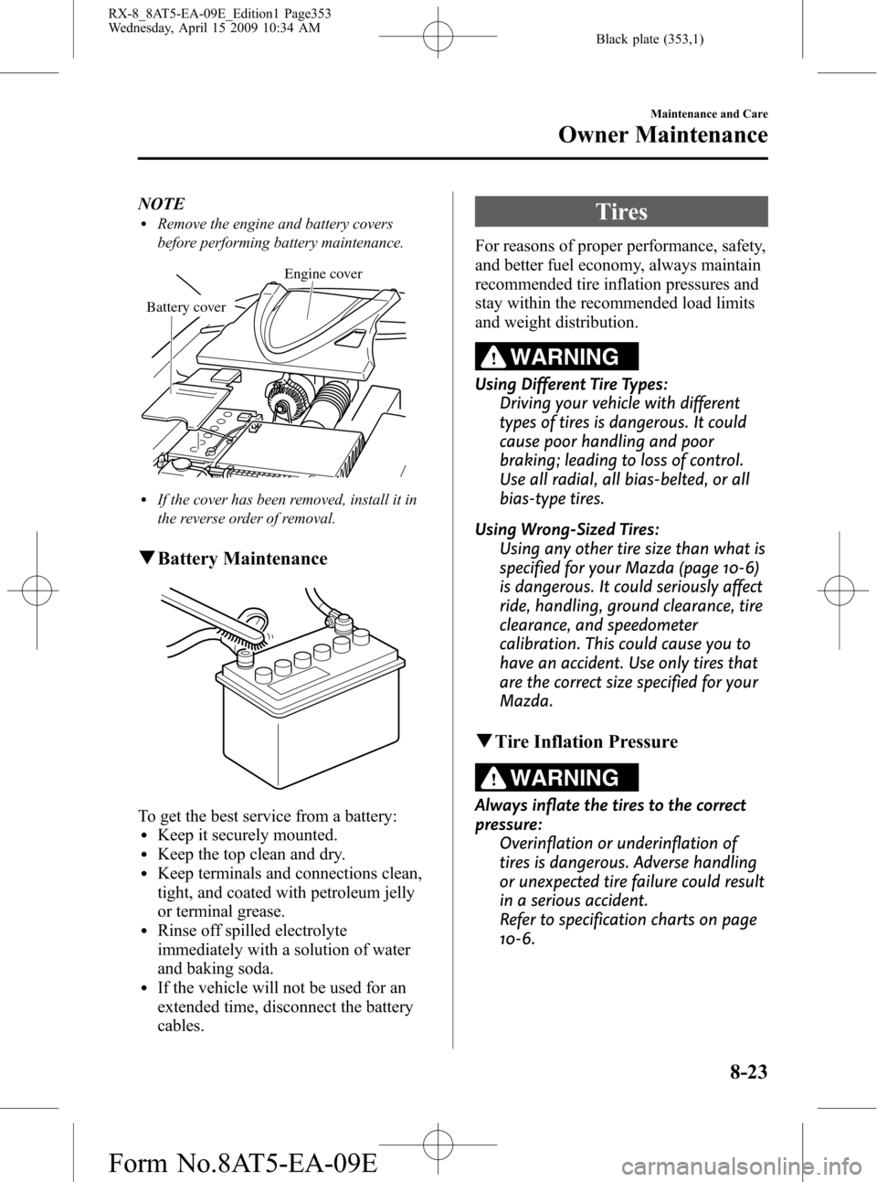
NOTElRemove the engine and battery covers
before performing battery maintenance.
Engine cover
Battery cover
lIf the cover has been removed, install it in
the reverse order of removal.
qBattery Maintenance
To get the best service from a battery:lKeep it securely mounted.lKeep the top clean and dry.lKeep terminals and connections clean,
tight, and coated with petroleum jelly
or terminal grease.
lRinse off spilled electrolyte
immediately with a solution of water
and baking soda.
lIf the vehicle will not be used for an
extended time, disconnect the battery
cables.
Tires
For reasons of proper performance, safety,
and better fuel economy, always maintain
recommended tire inflation pressures and
stay within the recommended load limits
and weight distribution.
WARNING
Using Different Tire Types:
Driving your vehicle with different
types of tires is dangerous. It could
cause poor handling and poor
braking; leading to loss of control.
Use all radial, all bias-belted, or all
bias-type tires.
Using Wrong-Sized Tires:
Using any other tire size than what is
specified for your Mazda (page 10-6)
is dangerous. It could seriously affect
ride, handling, ground clearance, tire
clearance, and speedometer
calibration. This could cause you to
have an accident. Use only tires that
are the correct size specified for your
Mazda.
qTire Inflation Pressure
WARNING
Always inflate the tires to the correct
pressure:
Overinflation or underinflation of
tires is dangerous. Adverse handling
or unexpected tire failure could result
in a serious accident.
Refer to specification charts on page
10-6.
Maintenance and Care
Owner Maintenance
8-23
RX-8_8AT5-EA-09E_Edition1 Page353
Wednesday, April 15 2009 10:34 AM
Form No.8AT5-EA-09E
Page 360 of 438

Black plate (360,1)
5. Turn the socket and bulb assembly to
remove it. Carefully remove the bulb
from its socket in the reflector by
gently pulling it straight backward out
of the socket.
6. Install the new bulb in the reverse order
of the removal procedure.
NOTE
lTo replace the bulb, contact an Authorized
Mazda Dealer.
lIf the halogen bulb is accidentally touched,
it should be cleaned with rubbing alcohol
before being used.
lUse the protective cover and carton of the
replacement bulb to dispose of the old bulb
promptly out of the reach of children.
Replacing a Fog Light Bulb
1. Remove the fog light cover by pulling
it outward using both hands.
2. Loosen the screws securing the fog
light unit.
8-30
Maintenance and Care
Owner Maintenance
RX-8_8AT5-EA-09E_Edition1 Page360
Wednesday, April 15 2009 10:34 AM
Form No.8AT5-EA-09E
Page 363 of 438

Black plate (363,1)
Reverse lights
Rear side marker lights
4. Install the new bulb in the reverse order
of the removal procedure.
High-mount brake light
1. Wrap the end of a flathead screwdriver
in a soft cloth and remove the trunk
handle by inserting the flathead
screwdriver in the position shown in
the figure and carefully prying the
handle off.
2. Disengage the pin in each clip securing
the trunk trim using a (
) screwdriver,
remove the screws and clips, and then
remove the trunk trim.
Removal
Installation
Maintenance and Care
Owner Maintenance
8-33
RX-8_8AT5-EA-09E_Edition1 Page363
Wednesday, April 15 2009 10:34 AM
Form No.8AT5-EA-09E
Page 368 of 438

Black plate (368,1)
3. If any fuse but the MAIN fuse is
blown, replace it with a new oneof the
same amperage rating.
Normal
Blown
WARNING
Do not replace the main fuse by
yourself. Have an Authorized Mazda
Dealer perform the replacement:
Replacing the fuse by yourself is
dangerous because the MAIN fuse is
a high current fuse. Incorrect
replacement could cause an electrical
shock or a short circuit resulting in a
fire.
NOTE
Verify that the engine cover is securely
installed.
8-38
Maintenance and Care
Owner Maintenance
RX-8_8AT5-EA-09E_Edition1 Page368
Wednesday, April 15 2009 10:34 AM
Form No.8AT5-EA-09E
Page 434 of 438

Black plate (434,1)
F
Flasher
Hazard warning .......................... 5-67
Flat Tire ............................................... 7-3
Changing .................................... 7-11
Instant Mobility System
(IMS) Emergency Flat Tire Repair
Kit ................................................ 7-5
Spare tire and tool storage ............ 7-3
Fluids
Classification .............................. 10-4
Owner maintenance ..................... 8-8
Fog Lights ......................................... 5-61
Foot Brake .......................................... 5-5
Front Seats
(Electrically Operated Seats) ............... 2-6
Front Seats
(Manually Operated Seats) ................. 2-2
Fuel
Filler lid and cap ........................ 3-43
Gauge ......................................... 5-38
Requirements ............................... 4-2
Tank capacity ............................. 10-5
Fuses ................................................. 8-36
Panel description ........................ 8-39
Replacement ............................... 8-36
G
Gauges .............................................. 5-35
Glove Box ......................................... 6-84
H
Hazard Warning Flasher .................... 5-67
Hazardous Driving .............................. 4-7
Headlight Washer .............................. 5-65
H
Headlights
Control ....................................... 5-57
Flashing ...................................... 5-59
High-low beam .......................... 5-59
Leveling ..................................... 5-59
On reminder ............................... 5-59
HomeLink Wireless Control
System .............................................. 5-68
Hood Release .................................... 3-45
Horn .................................................. 5-67
I
Ignition
Keys ........................................... 3-22
Switch .......................................... 5-2
Illuminated Entry System ................. 6-77
Immobilizer System
(with Advanced Key) ........................ 3-48
Immobilizer System
(without Advanced Key) ................... 3-51
Indicator Lights ................................. 5-40
Cruise ......................................... 5-54
DSC OFF .................................... 5-53
Headlight auto-leveling
malfunction ................................ 5-55
Headlight high-beam .................. 5-52
Power steering malfunction ........ 5-54
Security ...................................... 5-52
Shift position .............................. 5-53
TCS/DSC ................................... 5-53
Turn-signal/hazard warning ....... 5-55
Information Display .......................... 6-79
Ambient temperature display ..... 6-80
Audio display ............................. 6-81
Climate control display .............. 6-81
Clock .......................................... 6-80
Information display functions .... 6-79
11-4
Index
RX-8_8AT5-EA-09E_Edition1 Page434
Wednesday, April 15 2009 10:34 AM
Form No.8AT5-EA-09E