check engine light MAZDA MX-5 1994 Workshop Manual
[x] Cancel search | Manufacturer: MAZDA, Model Year: 1994, Model line: MX-5, Model: MAZDA MX-5 1994Pages: 1708, PDF Size: 82.34 MB
Page 23 of 1708
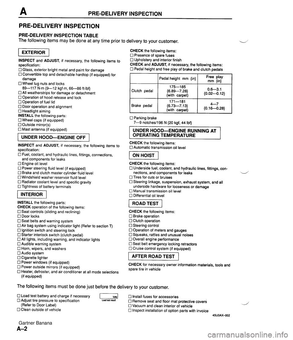
PRE-DELIVERY INSPECTION PRE-DELIVERY INSPECTION PRE-DELIVERY INSPECTION TABLE The following items may be done at any time prior to delivery to your customer. INSPECT and ADJUST, if necessary, the following items to specification: 0 Glass, exterior bright metal and paint for damage 0 Convertible top and detachable hardtop (if equipped) for damage 0 Wheel lug nuts and locks 89-117 N.m (9-1 2 kgf.m, 66-86 ft4bf) 0 All weatherstrips for damage or detachment Operation of hood release and lock Operation of fuel lid 0 Door operation and alignment Headlight aiming INSTALL the following parts: Wheel caps (if equipped) 0 Outside mirror(s) 0 Mast antenna (if equipped) UNDER HOOD-ENGINE OFF INSPECT and ADJUST, if necessary, the following items to specification : Fuel, coolant, and hydraulic lines, fittings, connections, and components for leaks Engine oil level 0 Power steering fluid level (if equipped) Brake and clutch master cylinder fluid level 0 Windshield washer reservoir fluid level 0 Radiator coolant level and specific gravity 0 Tightness of battery terminals pKiq INSTALL the following parts: CHECK operation of the following items: 0 Seat controls (sliding and reclining) 0 Door locks 0 Seat belts and warning system 0 Air bag system using indicator light (Refer to section T) Ignition switch and steering lock 0 Starter interlock switch (clutch pedal) All lights, including warning, and indicator lights 0 Audible warning system 0 Horn, wipers, and washers Audio system 0 Cigarette lighter Power windows (if equipped) 0 Power outside mirrors (if equipped) 0 Heater, defroster, and air conditioner at all mode selections (if equipped) CHECK the following items: Presence of spare fuses 0 Upholstery and interior finish CHECK and ADJUST, if necessary, the following items: 0 Pedal height and free play of brake and clutch pedals I Pedal height mm {in} I Ft: $iy I Clutch pedal {6.89--7.28) (with carpet) Parking brake 7-9 notchesil96 N (20 kgf, 44 Ibf) 0.63.1 (0.024. 12) Brake pedal RUNNING AT OPERATING TEMPERATURE CHECK the following items: 0 Automatic transmission oil level 171-181 (6.73--7.13) (with carpet) I ON HOIST I 4--7 {0.16-0.28} CHECK the following items: 0 Underside fuel, coolant, and hydraulic lines, fittings, con- nections, and components for leaks 4 Tires for cuts or bruises 0 Steering linkage, suspension, exhaust system, and all underside hardware for looseness or damage Manual transmission oil level Differential oil level I ROAD TEST I CHECK the following items: Brake operation Clutch operation 0 Steering control 0 Operation of meters and gauges Squeaks, rattles and unusual noises 0 Overall engine performance Seat belt emergency locking retractors 0 Cruise control system (if equipped) I AFTER ROAD TEST I CHECK for necessary owner information materials, tools and spare tire in vehicle The following items must be done just before the delivery to your customer. 0 Load test battery and charge if necessary -1 Install fuses for accessories Adjust tire pressure to specification Load test fesuk 0 Remove seat and floor mat protective covers (Refer to Door Label) 0 Vacuum and clean interior of vehicle Clean outside of vehicle Inspect installation of option parts with invoice 45UOAX-002 Gartner Banana
Page 45 of 1708
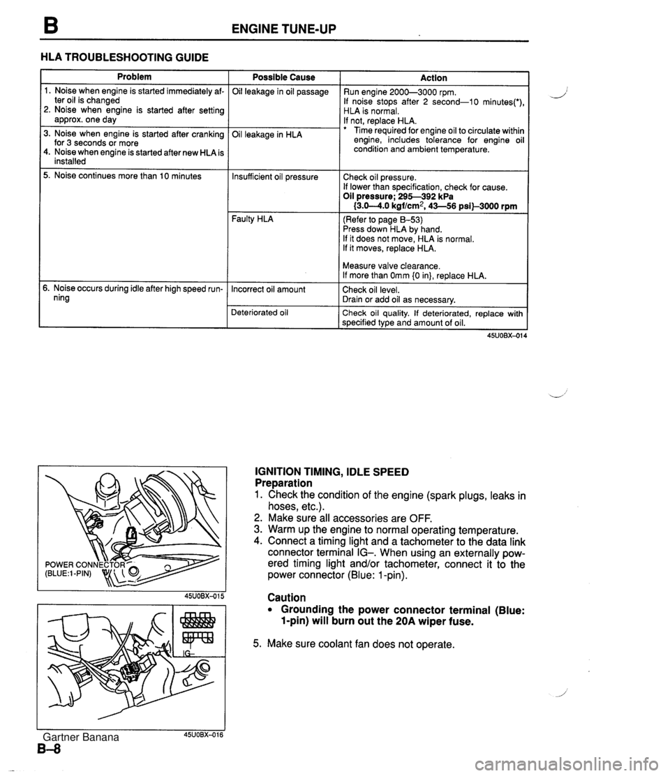
ENGINE TUNE-UP HLA TROUBLESHOOTING GUIDE Problem 1. Noise when engine is started immediately af- ter oil is changed 2. Noise when engine is started after setting approx. one day 3. Noise when engine is started after cranking for 3 seconds or more 4. Noise when engine is started after new HLA is installed 5. Noise continues more than 10 minutes 5. Noise occurs during idle after high speed run- ning Possible Cause Oil leakage in oil passage Oil leakage in HLA Faulty HLA Action Run engine 2000-3000 rpm. If noise stops after 2 second-10 minutes(') HLA is normal. If not, replace HLA. Time required for engine oil to circulate withir engine, includes tolerance for engine oi condition and ambient temperature. Insufficient oil pressure (Refer to page 8-53) Press down HLA by hand. If it does not move, HLA is normal. If it moves, replace HLA. Check oil pressure. If lower than specification, check for cause. Oil pressure; 295-392 kPa I3.0-4.0 kgf/cm2, 43-56 psil-3000 rpm Deteriorated oil Check oil quality. If deteriorated, replace with specified type and amount of oil. Incorrect oil amount IGNITION TIMING, IDLE SPEED Preparation 1. Check the condition of the engine (spark plugs, leaks in hoses, etc.). 2. Make sure all accessories are OFF. 3. Warm up the engine to normal operating temperature. 4. Connect a timing light and a tachometer to the data link connector terminal IG-. When using an externally pow- ered timing light and/or tachometer, connect it to the power connector (Blue: 1 -pin). Measure valve clearance. If more than Omm {0 in}, replace HLA. Check oil level. Drain or add oil as necessary. Caution Grounding the power connector terminal (Blue: 1-pin) will burn out the 20A wiper fuse. 5. Make sure coolant fan does not operate. Gartner Banana
Page 62 of 1708

ON-VEHICLE MAINTENANCE B Steps After Installation 1. Connect the neaative batterv cable. Oil seal 1. Cut the oil seal lip with a razor knife. 2. Remove the oil seal with a screwdriver protected with a rag. Installation Note Oil seal 1. Apply a small amount of clean engine oil to the lip of a new oil seal. 2. Push the oil seal slightly in by hand. 3. Tap the oil seal in evenly with a pipe and a hammer until it is flush with the edge of the oil pump body. Note Oil seal outer diameter: 50.5mm (1.99 in} Oil seal inner diameter: 36.5mm (1.44 in} Timing belt pulley 1. Install the timing belt pulley. 2. Install the pulley woodruff key with the tapered side to- ward the oil pump body. 2. Start the enginsand check, and if necessary, adjust the ignition timing. 3. Connect the negative battery cable. 4. Start the engine and check follows: (1) Engine coolant leakage (2) Ignition timing (Refer to page B-9.) 5. Recheck the engine coolant levels. Gartner Banana
Page 154 of 1708
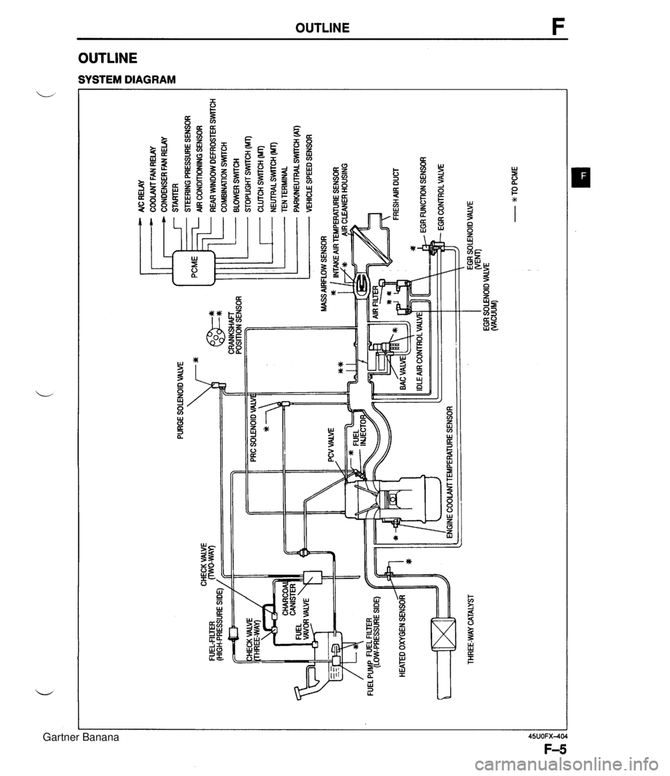
PURGE SOLENOID VALVE 7* AlC RELAY COOLANT FAN RELAY CONDENSER FAN RELAY STARTER STEERING PRESSURE SENSOR AIR CONDITIONING SENSOR ... CHECK VALVE FUEL-FILTER (HIGH-PRESSURE SIDE) / CRANKSHAFT POSITION SENSOR HEATED OXYGEN SENSOR ltT=I THREE-WAY CATALYST - REAR WINDOW DEFROSTER SWITCH COMBINATION SrmCH BLOWER SWlTCH STOPLIGHT SWITCH (MT) CLUTCH SWITCH (MT) - NEUTRALSWrrCH (MT) TEN TERMINAL PARWEUTRAL SWITCH (AT) VEHICLE SPEED SENSOR ENGINE COOLAMTEMPERATURE SENSOR EGR SOLENOID VALVE WEM) EGR SOLENOID VALVE (VACUUM) - w TO PCME Gartner Banana
Page 159 of 1708
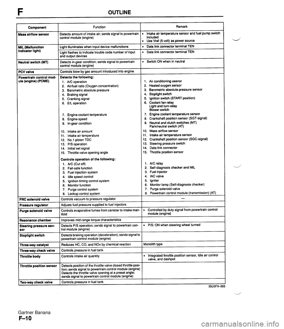
Neutral swltch (MT) 7 PCV valve Powertrain control mod- ule (engine) (PCME) Purge solenoid valve Resonance chamber Steering pressure sen- Stoplight swltch I Throttle posltion sensor r [Two-way check valve Function jetects amount of intake air; sends signal to powertrain :ontrol module (engine) Li~ht illuminates when input device malfunctions - Light flashes to indicate trouble code number of input and output devices Detects in-gear condition; sends signal to powertrain :ontrol module (engine) - Controls blow by aas amount introduced into engine Detects the followlng: 1. A/C operation 2. Airlfuel ratio (Oxygen concentration) 3. Barometric absolute pressure 4. Braking signal 5. Cranking signal 6. EIL operation 7. Engine coolant temperature 8. Engine speed 9. In-gear condition 10. lntake air amount 11, lntake air temperature 12. No.1 piston TDC 13. PIS operation 14. Initial set signal 15. Throttle valve opening angle Controls operatlon of the followlng: 1. AIC (Cut off) 2. Fail-safe function 3. Fuel injection system 4. ldle speed control 5. Ignition timing control system 6. Monitor function 7. Purge control system 8. Lockup control svstem Controls vacuum to pressure regulator -- Adjusts fuel pressure supplied to fuel injectors Controls evaporative fumes from canister to intake man- ifold -- lm~roves mid-ranae torque characteristics -. Detects PIS operation; sends signal to powertrain con- trol module (engine) -- Detects braking operation (deceleration); sends signal to powertrain control module (engine) Reduces HC, CO, and NOx by chemical reaction Controls pressurein fuel tank Controls intake air quantity Detects position of the throttle valve closed throttle posi- tion; sends signal to powertrain control module (engine) Detects the throttle valve opening at a preset angle; sends si~nal to powertrain control module (engine) controls pressure in fuel tank Remark lntake air temperature sensor and fuel pump switch included Use Vref (5 volt) as power source ' Data link connector terminal TEN ' Data link connector terminal TEN Switch ON when in neutral 1, Air conditioning sesnor 2. Heated oxygen sensor 3. Barometric absolute pressure sensor 4. Stoplight switch 5. Ignition switch (START position) 6. Coolant fan relay Light and turn relay Blower switch 7. Engine coolant temperature sensor 8. Crankshaft position sensor (SGT-signal) 9. Neutral and dutch switches (MT) Parklneutral switch (AT) 10. Mass airflow sensor 11, lntake air temperature sensor 12. Crankshaft position sensor (SGC-signal) 13. Steering pressure switch 14. Data link connector 15. Throttle position sensor 1. NC relay 2. Self-diagnosis checker and MIL 3. Fuel injector 4. IAC valve 5. Igniter 6. Monitor lamp (Self-diagnosis checker) 7. Purge solenoid valve 8. Powertrain control module (transmission) (AT) D Controlled by duty signal from powertrain control module (engine) D PIS: ON when steering wheel turned Monolith type D Integrated throttle position sensor, Idle air control valve, and dashpol Gartner Banana
Page 165 of 1708

TROUBLESHOOTING GUIDE Warning Fuel vapor is hazardous. It can very easily ignite, causing serious injury and damage. Always keep sparks and flames away from fuel. Fuel in the fuel system is under high pressure when the engine is not running. 4 Warning Fuel line spills and leaks are dangerous. Fuel can ignite and cause serious injuries or death and damage. Fuel can also irritate skin and eyes. To prevent this, always complete the following "Fuel Line Safety Procedures". 35UOFX-008 F-73 F-73 F-74 Fuel Line Safety Procedures A. Release the fuel pressure before disconnecting a fuel line. 1. Start the engine. u 2. Disconnect the fuel pump relay connector. 3. After the engine stalls, turn the ignition switch to OFF. 4. Reconnect the fuel pump relay connector. B. Avoid leakage. 1. When disconnecting a fuel line hose, wrap a rag around it to protect against fuel leakage. 2. Plug the hose after removal. C. Install hose clamps to secure the fuel pressure gauge connections. Self-Diagnosis Checker does not indicate Diagnostic Trouble Code No. but MIL comes on Self-Diagnosis Checker indicates Diagnostic Trouble Code No, of input device but MIL never comes ON Blower fan operates but no cool air is discharged 32 33 34 Pinching Hose When pinching an air hose or fuel hose with pliers, wrap the hose with a rag to prevent damage. MIL always ON MIL never ON NC does not work Checking ignition spark When checking ignition spark condition, hold the high- tension lead with insulated pliers. Note If a timing light is used to check for spark, some lights do not light at the number 2 and 4 cylinders even if the ignition system is normal. J Gartner Banana
Page 185 of 1708

TROUBLESHOOTING GUIDE ldle speed control malfunction Engine speed feedback control malfunction ldle air control valve stuck 12 INSPECTION LOW IDLE SPEED - WHEN AIC, PIS, OR EIL ON Check if "00" is displayed on Self-Diagnosis Check- er with ignition switch ON @? page F-79 SELECT SWA SYSTEM SELECT 1 I Check switches for correct operation with Self- Diagnosis Checker Monitor Lamp and ignition switch ON page F-95 SELECT SW A DESCRIPTIOH MONITOR [LAMP &\L SYSTEM SELECT 1 : Engine speed decreases at idle when NC, PIS, or EIL ON NC, PIS, headlights, blower fan and electric coolant fan operate normally Check if continuity exists between data link con- nector terminal TEN and ground --., rrROUBLESHOOTlNG HINTS] Disconnect idle air control valve connector at idle and check if engine condition is changed IAC VALYE CONNECTOR /' Yes - No Yes Yes No - Yes - No - ACTION Go to next step Diagnostic Trouble Code No. displayed Check for cause (Refer to specified check sequence) US= page F-81 "88" flashes Check PCME terminal 1 E voltage * page F-145 Specification: Battery positive voltage (Ignition switch ON) 6 If OK, replace PCME page F-143 G If not OK, check wiring between PCME and Self-Diagno- sis Checker page F-7 Go to next step Lamp not ONIOFF with specified switch Check for cause (Refer to specified check sequence) as page F-96 Lamp always ON Check wiring between PCME terminal I D and Self-Diag- nosis Checker @T page F-7 Check for short circuit in wiring between data link connec- tor terminal TEN and ground as page F-7 Go to next step Try known good PCME page F-144 Check idle air control valve @? page F-106 Gartner Banana
Page 199 of 1708
![MAZDA MX-5 1994 Workshop Manual TROUBLESHOOTING GUIDE DESCRIPTION I : Engine unexpectedly stops running at idle when AIC, PIS, or EIL ON AX, PIS, headlight, blower fan and electric coolant fan OK 20 [TROUBLESHOOTING HINTS] O ldle sp MAZDA MX-5 1994 Workshop Manual TROUBLESHOOTING GUIDE DESCRIPTION I : Engine unexpectedly stops running at idle when AIC, PIS, or EIL ON AX, PIS, headlight, blower fan and electric coolant fan OK 20 [TROUBLESHOOTING HINTS] O ldle sp](/img/28/57072/w960_57072-198.png)
TROUBLESHOOTING GUIDE DESCRIPTION I : Engine unexpectedly stops running at idle when AIC, PIS, or EIL ON AX, PIS, headlight, blower fan and electric coolant fan OK 20 [TROUBLESHOOTING HINTS] O ldle speed control malfunction No input signal from switch ldle speed misadjustment ldle air control valve stuck ENGINE STALLS AT IDLE - WHEN AIC, PIS, OR EIL ON INSPECTION Check if "00" is displayed on Self-Diagnosis Check- er with ignition switch ON * page F-79 SELECT SW A SYSTEM SELECT 1 Check switches for correct operation with Self- Diagnosis Checker Monitor Lamp and ignition switch ON tw page F-95 SELECT SW A Check if PCME terminal voltages are OK (IG, 1 P, 1 U, 2D,2Q and 2W) page F-146 Check for correct idle speed page F-77 ldle speed: 850 2 50 rpm (MT) 800 2 50 rpm (AT) GND TEN 1 AIR ADJUSTING SCREW CONNECT TERMINAL - Yes - No Yes - No Yes - No Yes - No Go to next step ACTION Diagnostic Trouble Code No. displayed Check for cause (Refer to specified check sequence) page F-81 "88" flashes Check PCME terminal 1 E voltage page F-145 Specification: Battery positive voltage (Ignition switch ON) 0 If OK, replace PCME page F-143 s If not OK, check wiring between PCME and Self-Diagno- sis Checker page F-7 Go to next step Lamp not ONlOFF with specified switch Check for cause (Refer to specified check sequence) page F-96 Lamp always ON Check wiring between PCME terminal 1 D and Self-Diag- nosis Checker IS page F-7 Go to next step Check for cause (Refer to "Check Point for Each Termi- nal") page F-148 Go to next step Adjust page F-77 Gartner Banana
Page 225 of 1708
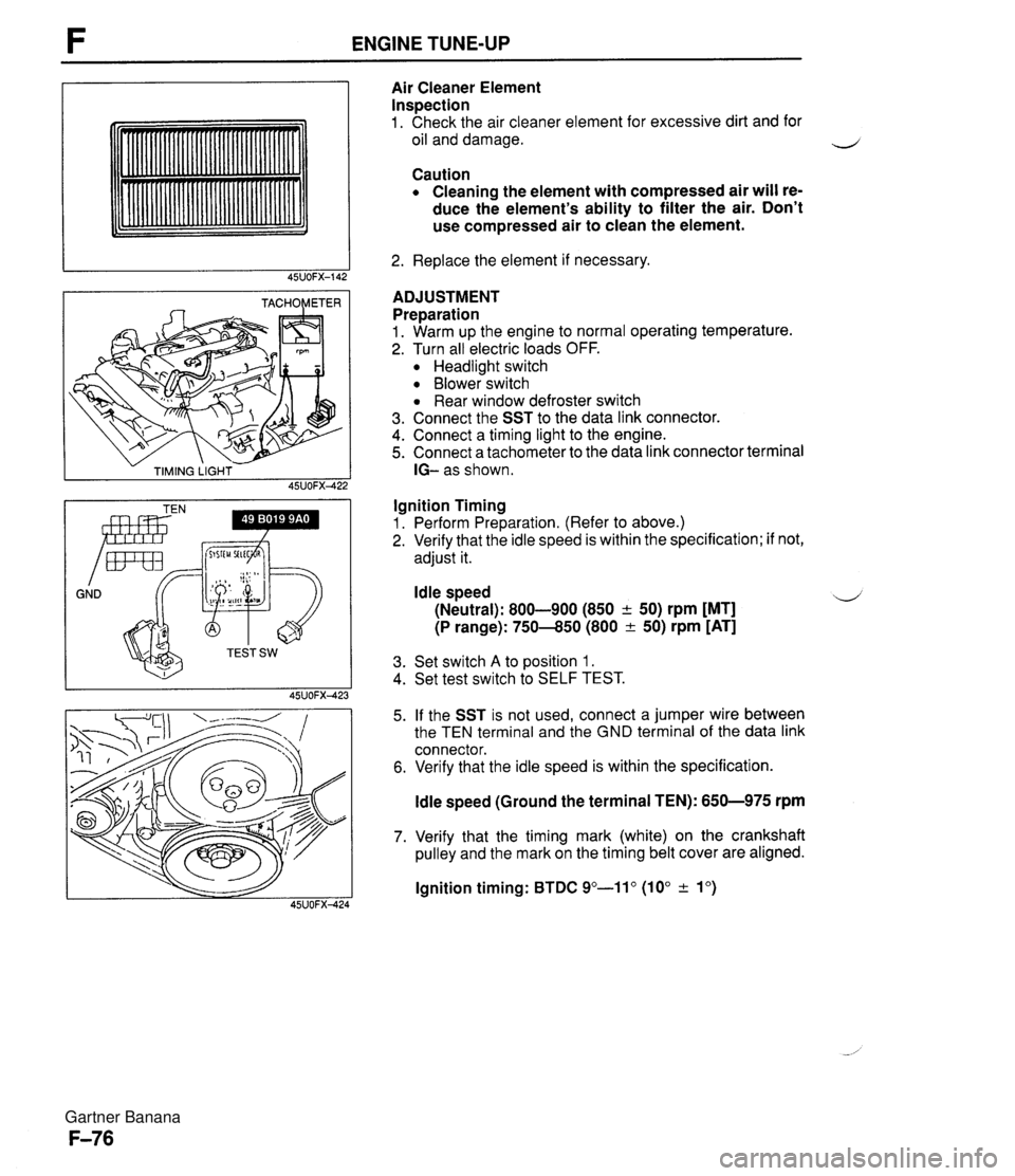
ENGINE TUNE-UP - TIMING LIGHT - 45UOFX422 GND Irnr Air Cleaner Element Inspection 1. Check the air cleaner element for excessive dirt and for oil and damage. Caution Cleaning the element with compressed air will re- duce the element's ability to filter the air. Don't use compressed air to clean the element. 2. Replace the element if necessary. ADJUSTMENT Preparation 1. Warm up the engine to normal operating temperature. 2. Turn all electric loads OFF. Headlight switch Blower switch Rear window defroster switch 3. Connect the SST to the data link connector. 4. Connect a timing light to the engine. 5. Connect a tachometer to the data link connector terminal IG- as shown. Ignition Timing 1. Perform Preparation. (Refer to above.) 2. Verify that the idle speed is within the specification; if not, adjust it. Idle speed 4 (Neutral): 800-900 (850 + 50) rpm [MT] (P range): 750-850 (800 & 50) rpm [AT] 3. Set switch A to position 1. 4. Set test switch to SELF TEST. 5. If the SST is not used, connect a jumper wire between the TEN terminal and the GND terminal of the data link connector. 6. Verify that the idle speed is within the specification. ldle speed (Ground the terminal TEN): 650-975 rpm 7. Verify that the timing mark (white) on the crankshaft pulley and the mark on the timing belt cover are aligned. lgnition timing: BTDC 9"-11" (10" & lo) Gartner Banana
Page 244 of 1708
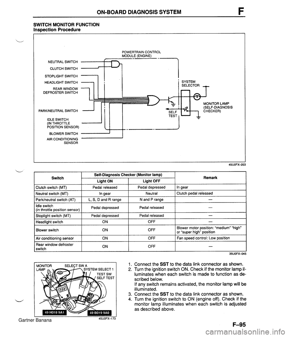
ON-BOARD DIAGNOSIS SYSTEM SWITCH MONITOR FUNCTION Inspection Procedure POWERTRAIN CONTROL MODULE (ENGINE) NEUTRAL SWITCH CLUTCH SWITCH 1 STOPLIGHT SWITCH HEADLIGHT SWITCH REAR WINDOW DEFROSTER SWITCH PARKINEUTRAL SWITCH IDLE SWITCH (IN THROTTLE POSITION SENSOR) BLOWER SWITCH AIR CONDITIONING SENSOR I ' SYSTEM MONITOR LAMP (SELF-DIAGNOSIS 1 Clutch switch (MT) 1 Pedal released I Pedal depressed I In gear I Switch Self-Diagnosis Checker (Monitor lamp) I Liaht ON Liaht OFF . . I I I - I Idle switch (in throttle position sensor) I Pedal depressed I Pedal released 1 Remark ParWneutral switch (AT) I L, S, D and R range I N and P range I I I Stoplight switch (MT) Pedal depressed I Pedal released - I Neutral I Clutch pedal released Neutral switch (MT) - In gear I I Blower switch Headlight switch OFF Blower motor position: "medium" "high" or "super hiah" position I I ON 1. Connect the SST to the data link connector as shown. 2. Turn the ignition switch ON. Check if the monitor lamp il- luminates when each switch is made to function as de- scribed below. If any switch remains activated, the monitor lamp will be illuminated. 3. Connect the SST to the data link connector as shown. 4. Turn the ignition switch to ON (engine off). Check if the monitor lamp illuminates when each switch is adjusted as described above. 45UOFX-173 OFF 1 Air conditioning sensor Rear window defroster switch - ON ON OFF OFF Fan speed control: Low position - Gartner Banana