fuel pump MAZDA MX-5 1994 Workshop Manual
[x] Cancel search | Manufacturer: MAZDA, Model Year: 1994, Model line: MX-5, Model: MAZDA MX-5 1994Pages: 1708, PDF Size: 82.34 MB
Page 10 of 1708
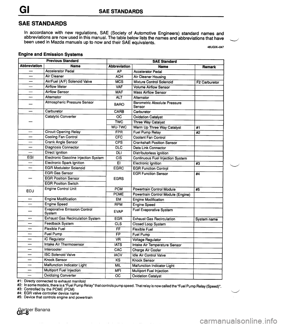
SAE STANDARDS SAE STANDARDS In accordance with new regulations, SAE (Society of Automotive Engineers) standard names and abbreviations are now used in this manual. The table below lists the names and abbreviations that have 4 been used in Mazda manuals up to now and their SAE equivalents. 46UGIX-047 Engine and Emission Systems Accelerator Pedal Air Cleaner Housing I Mixture Control Solenoid I F2 Carburetor ] Abbreviation AP ACH MCS VAF M AF Abbreviation - - - - - Volume Airflow Sensor I I Name Accelerator Pedal Air Cleaner AirlFuel (NF) Solenoid Valve Airflow Meter Airflow Sensor I Mass Airflow Sensor I I Alternator I I - - - -~ I Barometric Absolute Pressure I I Sensor I I Alternator Atmospheric Pressure Sensor I - 1 Carburetor CARB 1 Catalytic Converter OC ALT BAR0 Carburetor 1 Oxidation Catalvst I - - - - - I Direct Ignition I DL1 EG I 1 Electronic Gasoline lniection Svstem I CIS Three Way Catalyst Warm Up Three Way Catalyst Fuel Pump Relay Coolant Fan Control Crankshaft Position Sensor Data Link Connector Circuit Opening Relay Cooling Fan Control Crank Angle Sensor Diaanosis Connector Distributorless Ignition I Continuous Fuel lniection Svstem I 1 #1 #2 FPR C FC CPS DLC I Previous Standard SAE Standard Name I Remark - ( Electronic Spark Ignition EGR Gas Sensor EGR Position Sensor EGR Position Switch El Electronic Ignition 1 #3 EGR Function Control I - I EGR Modulator Solenoid I EGRC 4 ECU I Evaporative Emission Control Svstem I EVAP - - I -,--- I - I Exhaust Gas Recirculation System I EGR Engine Control Unit PCM PCME Engine Modification Ennine Speed EM RPM - - - - - Feedback System Flexible Fuel - I Intercooler Powertrain Control Module I #5 I EGR Function Sensor CLS FF Fuel Pump IC Regulator Intake Air Thermosensor CAC I Powertrain Control Module (Engine) I #4 FP VR IATS - I ISC Solenoid Valve I IACV Engine Modification I Engine Speed - Fuel Evaporative System I Exhaust Gas Recirculation 1 System name 1 Closed Loop System I Flexible Fuel Knock Sensor I I - ( Knock Sensor I KS I Malfunction Indicator Light I I - I Malfunction Indicator Liaht MIL Multiport Fuel Injection Oxidation Catalyst - 1 Multiport Fuel Injection #1: Directy connected to exhaust manifold #2: In some models, there is a "Fuel Pump Relay" that controls pump speed. That relay is now called the 'Fuel Pump Relay (Speed)". #3: Controlled by the PCME (PCM) 4 #4: EGR valve controller device name #5: Device that controls engine and powertrain MFI - 1 Oxidizina Converter OC Gartner Banana
Page 41 of 1708

B TROUBLESHOOTING GUIDE Problem nsufficlent power 4bnormal combustion Engine noise Possible Cause Insufficient compression Malfunction of HLA' Compression leakage from valve seat Seized valve stem Weak or broken valve spring Failed cylinder head gasket Cracked or distorted cylinder head Stuck, damaged, or worn piston ring Cracked or worn piston Malfunction of fuel system Malfunction of ignition system Others Slipping clutch Dragging brakes Wrong size tires Malfunction of engine-related components Malfunction of HLA* Stuck or burned valve Weak or broken valve spring Carbon accumulation in combustion chamber Malfunction of fuel system Malfunction of ignition system Crankshaft- or bearing-related parts Excessive main bearing oil clearance Main bearing seized or heat-damaged Excessive crankshaft end play Excessive connecting rod bearing oil clearance Connecting rod bearing seized or heat-damaged Piston-related parts Worn cylinder Worn piston or piston pin Seized piston Damaged piston ring Bent connecting rod Valves or timing-related parts Malfunction of HLA' Broken valve spring Excessive valve auide clearance Malfunction of cooling system Malfunction of fuel system Others Malfunction of water pump bearing Improper drive belt tension Malfunction of alternator bearing Exhaust gas leakage Malfunction of timina belt tensioner Remedy Replace Repair Replace Replace Replace Replace Replace Replace Refer to section F Refer to section G Refer to section H Refer to section P Refer to section Q Replace Replace Replace Eliminate carbon Refer to section F Refer to section G Replace or repair Replace Replace or repair Replace or repair Replace Replace or repair Replace Replace Replace Replace Replace Replace Replace Refer to section E Refer to section F Refer to section E Adjust Refer to section G Refer to section F Replace Page Tappet noise may occur if the engine has set idle for an extended period. The noise should dissipate after the engine has reached normal operating temperature. (HLA troubleshooting: Refer to page 6-8) Gartner Banana
Page 65 of 1708

B REMOVAL REMOVAL Caution Fuel line spills and leaks are dangerous. Fuel can ignite and cause serious injuries or death -d and damage. Fuel can also irritate skin and eyes. To prevent this, always complete the "Fuel Line safety Procedures" on section F. PROCEDURE 1. Disconnect the negative battery cable. 2. Drain the engine coolant. (Refer to section E.) 3. Remove the transmission. 4. Remove in the order shown in the figure, referring to Removal Note. Step 1 1. Air cleaner housing assembly 2. Accelerator cable 3. Radiator hose 4. Oil cooler hose 5. Coolant reservoir hose 6. Fan connector 7. Radiator and fan assembly 8. PIS andlor A/C drive belt ................ Removal 9. Alternator drive belt .................. Removal page B- 6 10. PIS oil pump (If equipped) ............. Removal Note page 529 11. AIC compressor (If equipped) Removal Note ............. page 529 1 page B- 6 Gartner Banana
Page 66 of 1708
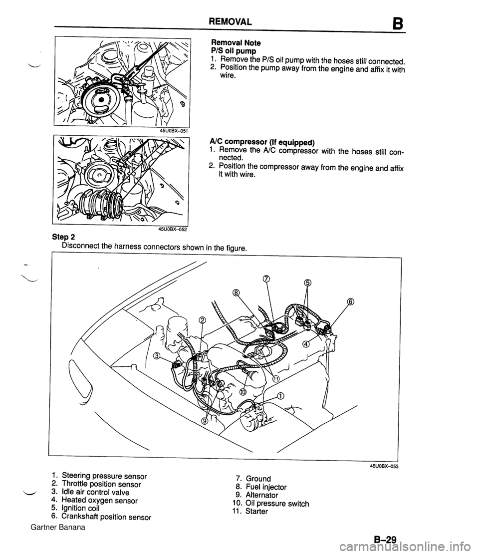
REMOVAL 6 Removal Note PIS oil pump 1. Remove the PIS oil pump with the hoses still connected. 2. Position the pump away from the engine and affix it with wire. 45UOBX-051 AIC compressor (If equipped) 1. Remove the NC compressor with the hoses still con- nected. 2. Position the compressor away from the engine and affix it with wire. I I 45UOBX-052 Step 2 Disconnect the harness connectors shown in the figure. 6 1. Steering pressure sensor 2. Throttle position sensor 3. Idle air control valve 4. Heated oxygen sensor 5. Ignition coil 6. Crankshaft position sensor 7. Ground 8. Fuel injector 9. Alternator 10. Oil pressure switch 11. Starter Gartner Banana
Page 150 of 1708
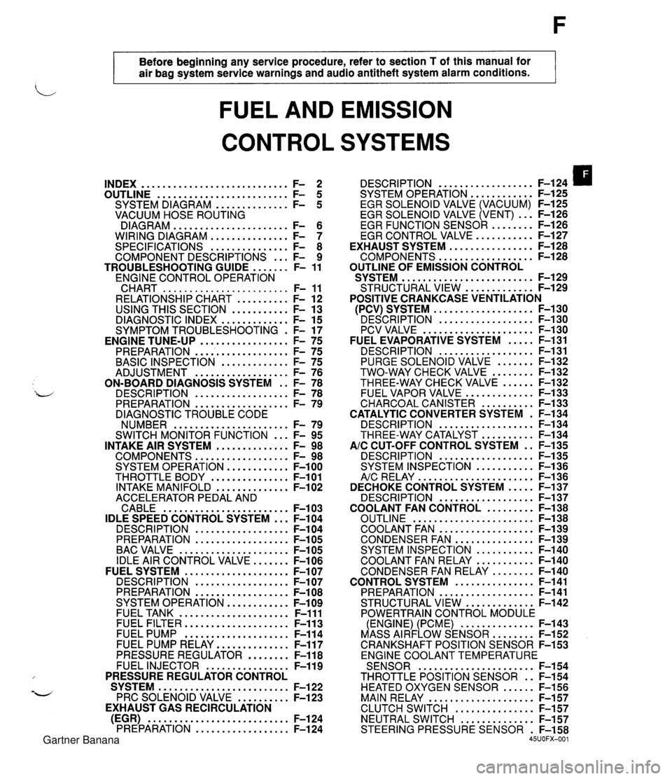
Before beginning any service procedure. refer to section T of this manual for air bag system service warnings and audio antitheft system alarm conditions . FUEL AND EMISSION CONTROL SYSTEMS INDEX ............................ F- 2 ......................... OUTLINE F- 5 .............. SYSTEM DIAGRAM F- 5 VACUUM HOSE ROUTING DIAGRAM ...................... F- 6 WIRING DIAGRAM ............... F- 7 SPECIFICATIONS ............... F- 8 COMPONENT DESCRIPTIONS ... F- 9 ....... TROUBLESHOOTING GUIDE F- 11 ENGINE CONTROL OPERATION CHART ........................ F- 11 RELATIONSHIP CHART .......... F- 12 USING THIS SECTION ........... F- 13 DIAGNOSTIC INDEX ............. F- 15 SYMPTOM TROUBLESHOOTING . F- 17 PREPARATION ................... F- 75 ............. BASIC INSPECTION F- 75 .................. ADJUSTMENT F- 76 ON-BOARD DIAGNOSIS SYSTEM . . F- 78 DESCRIPTION .................. F- 78 PREPARATION .................. F- 79 DIAGNOSTIC TROUBLE CODE NUMBER ...................... F- 79 ... SWITCH MONITOR FUNCTION F- 95 INTAKE AIR SYSTEM .............. F- 98 COMPONENTS .................. F- 98 SYSTEM OPERATION ............ F-100 THROTTLE BODY ............... F-101 INTAKE MANIFOLD .............. F-102 ACCELERATOR PEDAL AND CABLE ........................ F-103 IDLE SPEED CONTROL SYSTEM ... F-104 DESCRI PTlON .................. F-104 PREPARATION .................. F-105 BAC VALVE ..................... F-105 IDLE AIR CONTROL VALVE ....... F-106 FUEL SYSTEM .................... F-107 DESCRIPTION .................. F-107 PREPARATION .................. F-108 SYSTEM OPERATION ............ F-109 FUEL TANK ..................... F-111 FUEL FILTER .................... F-113 FUEL PUMP .................... F-114 FUEL PUMP RELAY .............. F-117 PRESSURE REGULATOR ........ F-118 FUEL INJECTOR ................ F-119 PRESSURE REGULATOR CONTROL SYSTEM ......................... F-122 PRC SOLENOID VALVE .......... F-123 EXHAUST GAS RECIRCULATION (EGR) ........................... F-124 PREPARATION .................. F-124 .................. DESCRIPTION F-124 SYSTEM OPERATION F-125 ............ EGR SOLENOID VALVE (VACUUM) F-125 EGR SOLENOID VALVE (VENT) ... F-126 ......... EGR FUNCTION SENSOR F-126 ........... EGR CONTROL VALVE F-127 ................ EXHAUST SYSTEM F-128 .................. COMPONENTS F-128 OUTLINE OF EMISSION CONTROL ......................... SYSTEM F-129 ............. STRUCTURAL VIEW F-129 POSITIVE CRANKCASE VENTILATION ................... (PCV) SYSTEM F-130 ' DESCRIPTION .................. F-I ..................... PCV VALVE F-1 ..... FUEL EVAPORATIVE SYSTEM F- .................. DESCRIPTION F- ....... PURGE SOLENOID VALVE F- ........ TWO-WAY CHECK VALVE F- ...... THREE-WAY CHECK VALVE F- ............. FUEL VAPOR VALVE F- .......... CHARCOAL CANISTER F- CATALYTIC CONVERTER SYSTEM . F- .................. DESCRIPTION F- .......... THREE-WAY CATALYST F- AIC CUT-OFF CONTROL SYSTEM . . F- .................. DESCRIPTION F- ........... SYSTEM INSPECTION F- ...................... A/c RELAY F-1 36 ..... DECHOKE CONTROL SYSTEM F-137 .................. DESCRIPTION F-137 ......... COOLANT FAN CONTROL F-138 ....................... OUTLINE F-138 .................. COOLANT FAN F-139 ............... CONDENSER FAN F-139 ........... SYSTEM INSPECTION F-140 ........... COOLANT FAN RELAY F-140 ........ CONDENSER FAN RELAY F-140 ............... CONTROL SYSTEM F-141 .................. PREPARATION F-141 ............. STRUCTURAL VIEW F-142 POWERTRAIN CONTROL MODULE .............. (ENGINE) (PCME) F-143 ........ MASS AIRFLOW SENSOR F-152 CRANKSHAFT POSITION SENSOR F-153 ENGINE COOLANT TEMPERATURE ...................... SENSOR F-154 THROTTLE POSITION SENSOR . . F-154 HEATED OXYGEN SENSOR ...... F-156 MAIN RELAY .................... F-157 ............... CLUTCH SWITCH F-157 NEUTRAL SWITCH .............. F-157 STEERING PRESSURE SENSOR . F-158 45UOFX-001 Gartner Banana
Page 152 of 1708
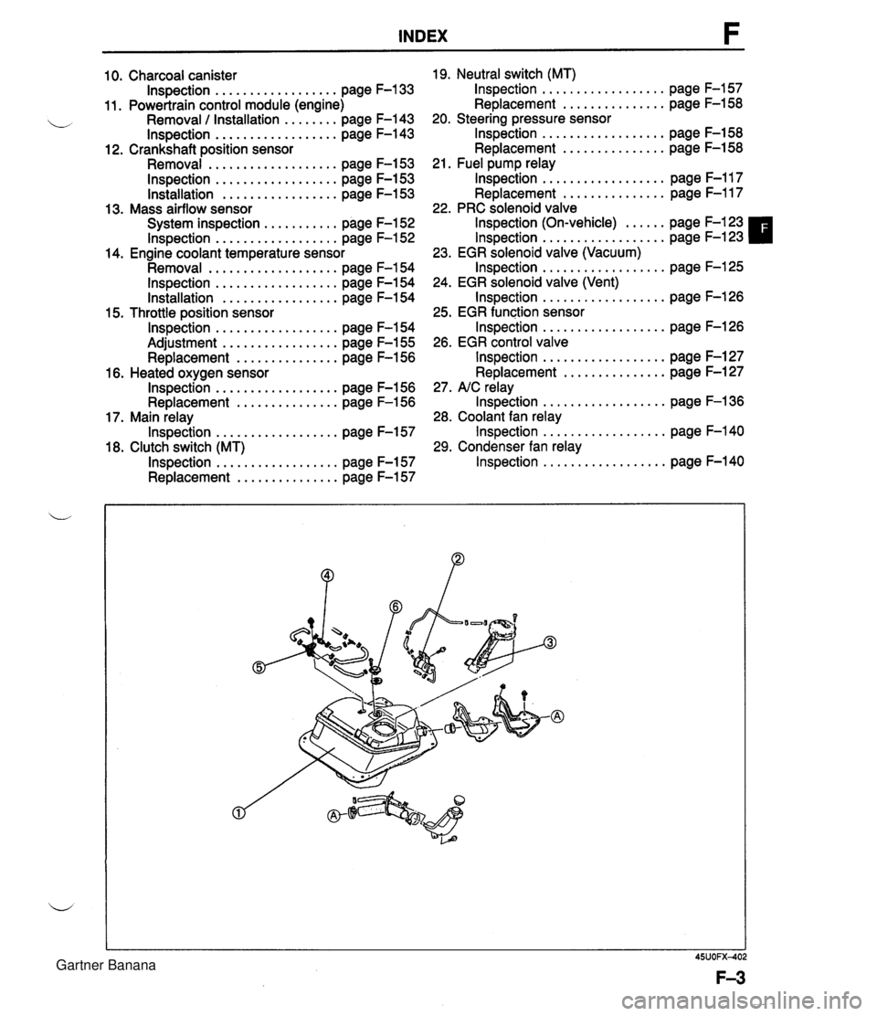
INDEX 10. Charcoal canister lnspection . . . . . . . . . . . . . . . . . . page F-133 11. Powertrain control module (engine) Removal / Installation . . . . . . . . page F-143 lnspection . . . . . . . . . . . . . . . . . . page F-143 12. Crankshaft position sensor Removal . . . . . . . . . . . . . . . . . . . page F-153 lnspection . . . . . . . . . . . . . . . . . . page F-153 lnstallation . . . . . . . . . . . . . . . . . page F-153 13. Mass airflow sensor System inspection . . . . . . . . . . . page F-152 lnspection . . . . . . . . . . . . . . . . . . page F-152 14. Engine coolant temperature sensor Removal . . . . . . . . . . . . . . . . . . . page F-154 lnspection . . . . . . . . . . . . . . . . . . page F-154 Installation . . . . . . . . . . . . . . . . . page F-154 15. Throttle position sensor lnspection . . . . . . . . . . . . . . . . . . page F-154 Adjustment . . . . . . . . . . . . . . . . . page F-155 Replacement . . . . . . . . . . . . . . . page F-156 16. Heated oxygen sensor lnspection . . . . . . . . . . . . . . . . . . page F-156 Replacement . . . . . . . . . . . . . . . page F-156 17. Main relay lnspection . . . . . . . . . . . . . . . . . . page F-157 18. Clutch switch (MT) lnspection . . . . . . . . . . . . . . . . . . page F-157 Replacement . . . . . . . . . . . . . . . page F-157 19. Neutral switch (MT) lnspection . . . . . . . . . . . . . . . . . . page F-157 Replacement . . . . . . . . . . . . . . . page F-158 20. Steering pressure sensor lnspection . . . . . . . . . . . . . . . . . . page F-158 Replacement . . . . . . . . . . . . . . . page F-158 21. Fuel pump relay lnspection . . . . . . . . . . . . . . . . . . page F-117 Replacement . . . . . . . . . . . . . . . page F-117 22. PRC solenoid valve lnspection (On-vehicle) . . . . . . page F-123 lnspection . . . . . . . . . . . . . . . . . . page F-123 23. EGR solenoid valve (Vacuum) lnspection . . . . . . . . . . . . . . . . . . page F-125 24. EGR solenoid valve (Vent) lnspection . . . . . . . . . . . . . . . . . . page F-126 25. EGR function sensor lnspection . . . . . . . . . . . . . . . . . . page F-126 26. EGR control valve lnspection . . . . . . . . . . . . . . . . . . page F-127 Replacement . . . . . . . . . . . . . . . page F-127 27. NC relay lnspection . . . . . . . . . . . . . . . . . . page F-136 28. Coolant fan relay lnspection . . . . . . . . . . . . . . . . . . page F-140 29. Condenser fan relay lnspection . . . . . . . . . . . . . . . . . . page F-140 Gartner Banana
Page 153 of 1708

INDEX 1. Fuel tank 4. Two-way check valve .................. Removal / Inspection / Inspection page F-132 Installation ................ page F-111 5. Three-way check valve .................. 2. Fuel filter Inspection page F-132 Replacement ............... page F-113 6. Fuel vapor valve .................. 3. Fuel pump Inspection page F-133 .................. Inspection page F-114 ............... Replacement page F-115 1. Three-way catalyst 2. Exhaust components d Inspection / Replacement .... page F-134 Removal / Inspection / Installation ............... page F-128 Gartner Banana
Page 157 of 1708
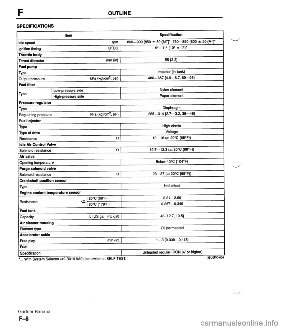
F OUTLINE SPECIFICATIONS Item Specification I Throttle body Throat diameter mm {in) I 55 I2.2) Idle speed rpm Ignition timing BTDC 800-900 (850 -+ 50)[MIb, 750-850 (800 + 50)[ATJe 9"-11" (10" k 1 ")* ~ut~~~ressure kPa {kgf/cm2, psi) 1 46-57 14.9--6.7,6%95) Fuel filter Fuel pump TY pe -- m&e regulator Impeller (in-tank) Low-pressure side Hi~h-pressure side Nylon element Paper element Fuel injector TY pe I High-ohmic Type Regulating pressure kPa {kgf/cm2, psi) Diaphragm 26S314 (2.7--3.2,38--46) ldle Air Control Valve Solenoid resistance n 1 10.7-1 2.3 (at 20°C {M°F)) Type of drive Resistance R Voltage 12-1 6 (at 20°C {68"F)) I Solenoid resistance 1 23-27 (at 20°C (68"FJ) I -- brankshaft position sensor d Air valve Opening temperature I Resistance Below 40°C {I 04°F) TY pe Capacity L {US gal, Imp gal) I 48 {12.7, 10.5) Air cleaner housing Purae solenoid valve Hall effect Engine coolant temperature sensor Free play mm (in) I 1-3 {0.0394.118) Fuel Specification 1 Unleaded regular (RON 87 or higher) Element type I I -. I *... With System Selector (49 B019 9AO) test switch at SELF TEST. 35UOFX-004 Oil permeated Accelerator cable Gartner Banana
Page 158 of 1708
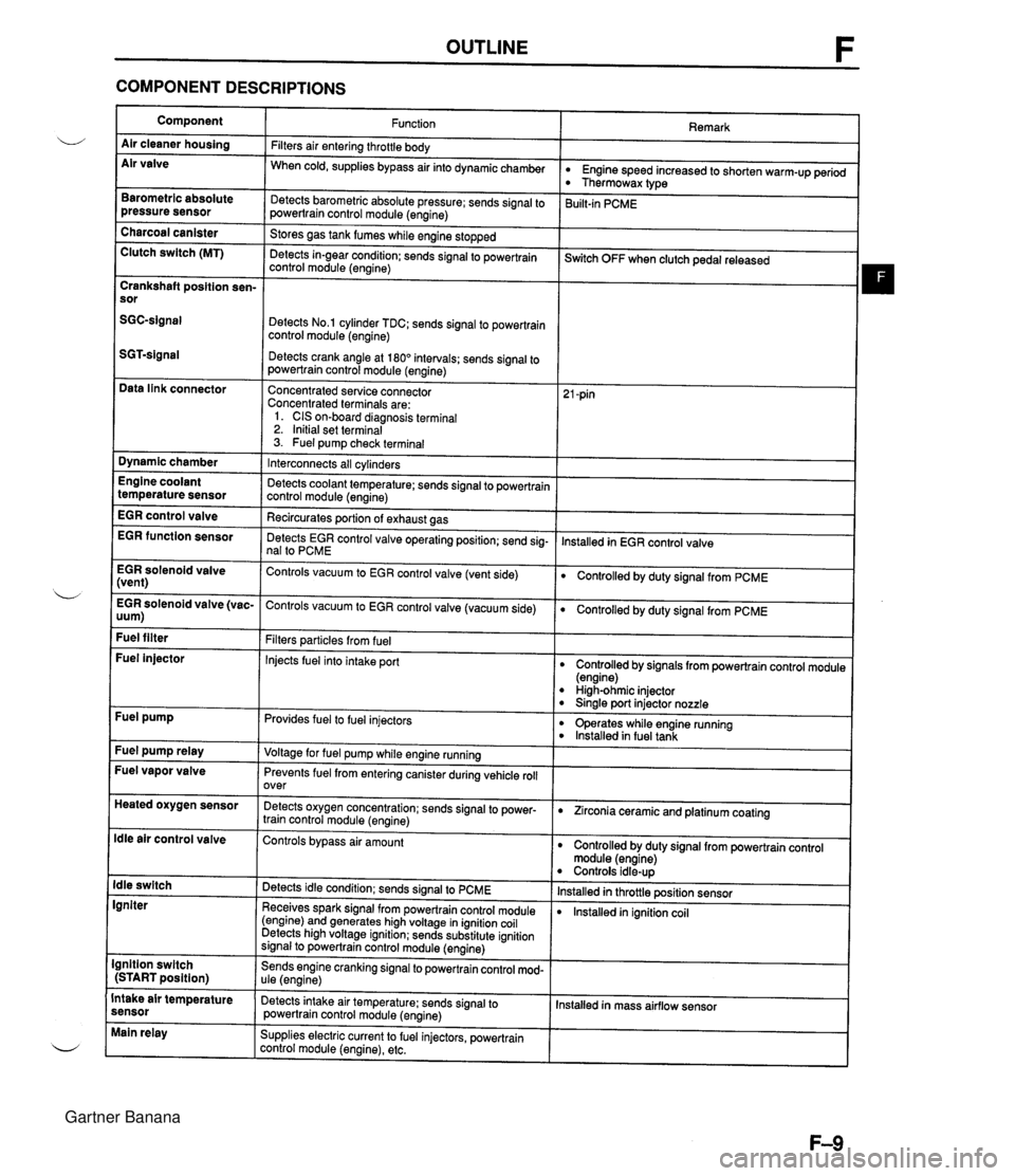
OUTLINE F COMPONENT DESCRIPTIONS Component Air cleaner housing Air valve Remark Function Filters air entering throttle body When cold, supplies bypass air into dynamicchamber w Engine speed increased to shorten warm-up period Thermowax type Barometric absolute pressure sensor Detects barometric absolute pressure; sends signal to powertrain control module (engine) 3uilt-in PCME Charcoal canister Clutch switch (MT) Stores gas tank fumes while engine stopped Detects in-gear condition: sends signal to powertrain control module (engine) --- ~witch OFF when clutch pedal released Crankshaft position sen- sor Detects No.1 cylinder TDC; sends signal to powertrain control module (engine) Detects crank angle at 180" intervals; sends signal to powertrain control module (engine) Data link connector Concentrated service connector Concentrated terminals are: 1. CIS on-board diagnosis terminal 2. Initial set terminal 3. Fuel pump check terminal Dynamic chamber Interconnects all cylinders Detects coolant temperature; sends signal to powertrain control module (engine) Recircurates oortion of exhaust aas Engine coolant temperature sensor EGR control valve lnstalled in EGR control valve EGR function sensor Detects EGR control valve operating position; send sig- nal to PCME EGR solenoid valve (vent) Controls vacuum to EGR control valve (vent side) Controlled by duty signal from PCME . - EGR solenoid valve (vac- Controls vacuum to EGR control valve (vacuum side) 0 Controlled by duty signal from PCME uum) Fuel filter Filters particles from fuel Injects fuel into intake port Fuel injector Controlled by signals from powertrain control module (engine) High-ohmic injector 0 Sinale port injector nozzle Fuel pump Provides fuel to fuel injectors 0 operates while engine running lnstalled in fuel tank Fuel pump relay Voltage for fuel pump while engine running Fuel vapor valve Prevents fuel from entering canister during vehicle roll over Heated oxygen sensor Detects oxygen concentration; sends signal to power- train control module (engine) 0 Zirconia ceramic and platinum coating ldle air control valve Controls bypass air amount Controlled by duty signal from powertrain control module (engine) Controls idle-up lnstalled in throttle position sensor lnstalled in ignition coil ldle switch Igniter Detects idle condition; sends signal to PCME Receives spark signal from powertrain control module (engine) and generates high voltage in ignition coil Detects high voltage ignition; sends substitute ignition signal to powertrain control module (engine) Ignition switch (START position) Sends engine cranking signal to powertrain control mod- ule (engine) Intake air temperature sensor Detects intake air temperature: sends signal to powertrain control module (engine) Installed in mass airflow sensor Main relay Supplies electric current to fuel injectors, powertrain control module (engine), etc. Gartner Banana
Page 159 of 1708
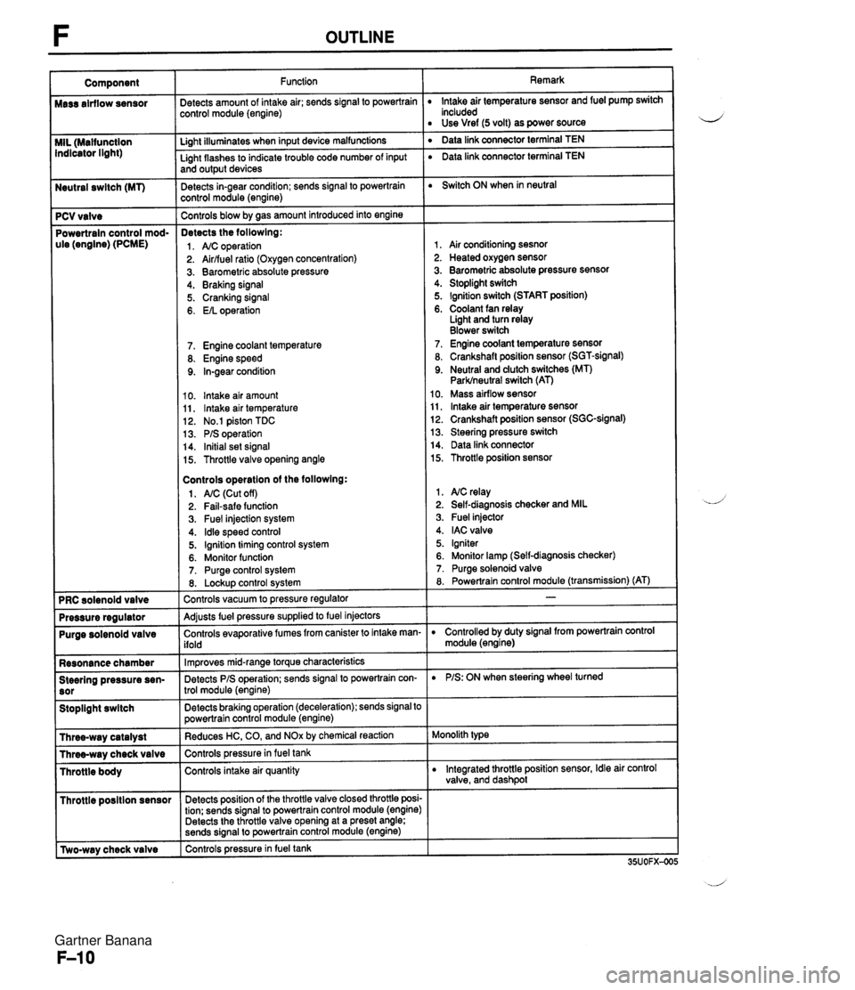
Neutral swltch (MT) 7 PCV valve Powertrain control mod- ule (engine) (PCME) Purge solenoid valve Resonance chamber Steering pressure sen- Stoplight swltch I Throttle posltion sensor r [Two-way check valve Function jetects amount of intake air; sends signal to powertrain :ontrol module (engine) Li~ht illuminates when input device malfunctions - Light flashes to indicate trouble code number of input and output devices Detects in-gear condition; sends signal to powertrain :ontrol module (engine) - Controls blow by aas amount introduced into engine Detects the followlng: 1. A/C operation 2. Airlfuel ratio (Oxygen concentration) 3. Barometric absolute pressure 4. Braking signal 5. Cranking signal 6. EIL operation 7. Engine coolant temperature 8. Engine speed 9. In-gear condition 10. lntake air amount 11, lntake air temperature 12. No.1 piston TDC 13. PIS operation 14. Initial set signal 15. Throttle valve opening angle Controls operatlon of the followlng: 1. AIC (Cut off) 2. Fail-safe function 3. Fuel injection system 4. ldle speed control 5. Ignition timing control system 6. Monitor function 7. Purge control system 8. Lockup control svstem Controls vacuum to pressure regulator -- Adjusts fuel pressure supplied to fuel injectors Controls evaporative fumes from canister to intake man- ifold -- lm~roves mid-ranae torque characteristics -. Detects PIS operation; sends signal to powertrain con- trol module (engine) -- Detects braking operation (deceleration); sends signal to powertrain control module (engine) Reduces HC, CO, and NOx by chemical reaction Controls pressurein fuel tank Controls intake air quantity Detects position of the throttle valve closed throttle posi- tion; sends signal to powertrain control module (engine) Detects the throttle valve opening at a preset angle; sends si~nal to powertrain control module (engine) controls pressure in fuel tank Remark lntake air temperature sensor and fuel pump switch included Use Vref (5 volt) as power source ' Data link connector terminal TEN ' Data link connector terminal TEN Switch ON when in neutral 1, Air conditioning sesnor 2. Heated oxygen sensor 3. Barometric absolute pressure sensor 4. Stoplight switch 5. Ignition switch (START position) 6. Coolant fan relay Light and turn relay Blower switch 7. Engine coolant temperature sensor 8. Crankshaft position sensor (SGT-signal) 9. Neutral and dutch switches (MT) Parklneutral switch (AT) 10. Mass airflow sensor 11, lntake air temperature sensor 12. Crankshaft position sensor (SGC-signal) 13. Steering pressure switch 14. Data link connector 15. Throttle position sensor 1. NC relay 2. Self-diagnosis checker and MIL 3. Fuel injector 4. IAC valve 5. Igniter 6. Monitor lamp (Self-diagnosis checker) 7. Purge solenoid valve 8. Powertrain control module (transmission) (AT) D Controlled by duty signal from powertrain control module (engine) D PIS: ON when steering wheel turned Monolith type D Integrated throttle position sensor, Idle air control valve, and dashpol Gartner Banana