jump start terminals MAZDA MX-5 1997 Factory Repair Manual
[x] Cancel search | Manufacturer: MAZDA, Model Year: 1997, Model line: MX-5, Model: MAZDA MX-5 1997Pages: 514, PDF Size: 17.89 MB
Page 37 of 514

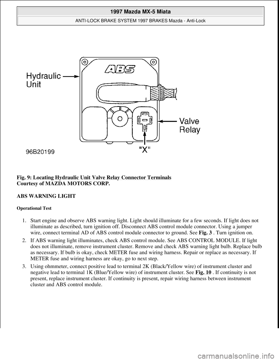
Fig. 9: Locating Hydraulic Unit Valve Relay Connector Terminals
Courtesy of MAZDA MOTORS CORP.
ABS WARNING LIGHT
Operational Test
1. Start engine and observe ABS warning light. Light should illuminate for a few seconds. If light does not
illuminate as described, turn ignition off. Disconnect ABS control module connector. Using a jumper
wire, connect terminal AD of ABS control module connector to ground. See Fig. 3
. Turn ignition on.
2. If ABS warning light illuminates, check ABS control module. See ABS CONTROL MODULE. If light
does not illuminate, remove instrument cluster. Remove and check ABS warning light bulb. Replace bulb
as necessary. If bulb is okay, check METER fuse and wiring harness. Repair or replace as necessary. If
METER fuse and wiring harness are okay, go to next step.
3. Using ohmmeter, connect positive lead to terminal 2K (Black/Yellow wire) of instrument cluster and
negative lead to terminal 1K (Blue/Yellow wire) of instrument cluster. See Fig. 10
. If continuity is not
present, replace instrument cluster. If continuity is present, repair wiring harness between instrument
cluster and ABS control module.
1997 Mazda MX-5 Miata
ANTI-LOCK BRAKE SYSTEM 1997 BRAKES Mazda - Anti-Lock
Microsoft
Sunday, July 05, 2009 1:48:49 PMPage 16 © 2005 Mitchell Repair Information Company, LLC.
Page 208 of 514

Remove rear seat cushions. Disconnect fuel pump connector. Start engine and allow to stall. After engine stalls,
attempt to restart engine to ensure no residual pressure exists. Turn ignition off and reconnect fuel pump
connector. When disconnecting fuel hoses, cover connection with shop rag to catch fuel leakage. To avoid
excessive cranking after servicing, prime fuel system before starting engine.
Priming System
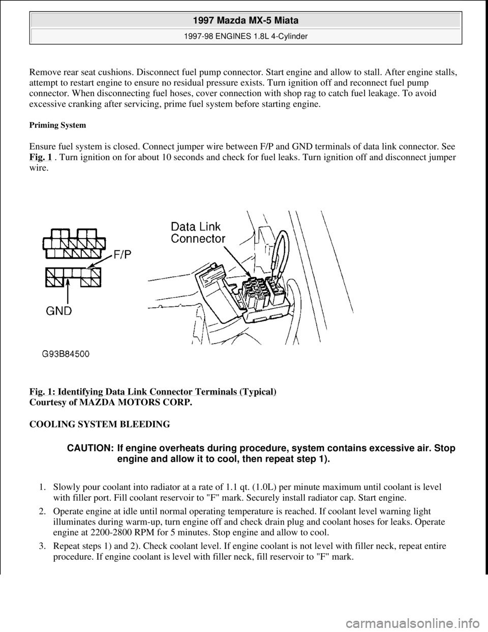
Ensure fuel system is closed. Connect jumper wire between F/P and GND terminals of data link connector. See
Fig. 1
. Turn ignition on for about 10 seconds and check for fuel leaks. Turn ignition off and disconnect jumper
wire.
Fig. 1: Identifying Data Link Connector Terminals (Typical)
Courtesy of MAZDA MOTORS CORP.
COOLING SYSTEM BLEEDING
1. Slowly pour coolant into radiator at a rate of 1.1 qt. (1.0L) per minute maximum until coolant is level
with filler port. Fill coolant reservoir to "F" mark. Securely install radiator cap. Start engine.
2. Operate engine at idle until normal operating temperature is reached. If coolant level warning light
illuminates during warm-up, turn engine off and check drain plug and coolant hoses for leaks. Operate
engine at 2200-2800 RPM for 5 minutes. Stop engine and allow to cool.
3. Repeat steps 1) and 2). Check coolant level. If engine coolant is not level with filler neck, repeat entire
procedure. If engine coolant is level with filler neck, fill reservoir to "F" mark.
CAUTION: If engine overheats during procedure, system contains excessive air. Stop
engine and allow it to cool, then repeat step 1).
1997 Mazda MX-5 Miata
1997-98 ENGINES 1.8L 4-Cylinder
Microsoft
Sunday, July 05, 2009 1:55:15 PMPage 2 © 2005 Mitchell Repair Information Company, LLC.
Page 391 of 514

NO-LOAD TEST
Connect fully-charged 12-volt battery, voltmeter and ammeter to starter. See Fig. 2
. Using remote starter wires
or jumper, engage solenoid. Starter should spin smoothly. Compare readings with specifications. See NO
-
LOAD TEST SPECIFICATIONS table. If voltage is less than specified, amperage is more than specified or
shaft speed is less than specified, disassemble and inspect starter components.
NO-LOAD TEST SPECIFICATIONS
SOLENOID TESTS
Solenoid Pull-In Test
Connect positive battery lead to solenoid "S" terminal and negative battery lead to starter body. See Fig. 2 .
Starter pinion drive gear should extend outward and stop. If starter pinion drive gear does not extend, replace
solenoid.
Solenoid Hold-In Test
After performing solenoid pull-in test, with positive battery lead connected to solenoid "S" terminal and
negative battery lead connected to starter body, disconnect field lead ("M" terminal wire) at solenoid. Starter
pinion drive gear should remain extended. If starter pinion drive gear returns, replace solenoid.
Solenoid Return Test
Disconnect field lead ("M" terminal wire) at solenoid. Connect positive battery lead to solenoid "M" terminal
and negative battery lead to starter body. See Fig. 2
. Using screwdriver, pry overrunning clutch pinion drive
outward. Release screwdriver and ensure overrunning clutch pinion drive returns to original position.
Solenoid
1. Disconnect all wires from solenoid, including "M" terminal wire between solenoid and starter. Using
ohmmeter, ensure continuity exists between "S" and "M" terminals, and between "S" terminal and
solenoid body. See Fig. 1
and Fig. 2 . If continuity does not exist between specified terminals, replace
solenoid.
2. Using ohmmeter, ensure continuity does not exist between "M" and "B" terminals. If continuity exists,
replace solenoid.
ApplicationSpecification
Voltage (Minimum)11
Amperage (Maximum)90
Shaft Speed (Minimum RPM)3000
CAUTION: Perform solenoid tests with starter and solenoid assembled. DO NOT
engage starter solenoid for more than 10 seconds during testing or
damage to coil winding may result.
1997 Mazda MX-5 Miata
STARTER - REDUCTION GEAR 1997 STARTING & CHARGING SYSTEMS Mazda - Starters - Reduction Gear
Microsoft
Sunday, July 05, 2009 1:56:43 PMPage 5 © 2005 Mitchell Repair Information Company, LLC.