power supply MERCEDES-BENZ A CLASS 2012 Owners Manual
[x] Cancel search | Manufacturer: MERCEDES-BENZ, Model Year: 2012, Model line: A CLASS, Model: MERCEDES-BENZ A CLASS 2012Pages: 356, PDF Size: 4.96 MB
Page 20 of 356
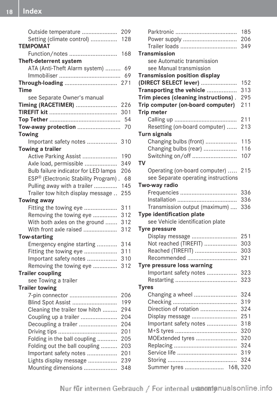
Outside temperature ...................... 209
Setting (climate control)
................128
TEMPOMAT
Function/notes ............................. 168
Theft-deterrent system
ATA (Anti-Theft Alarm system) .........69
Immobiliser ...................................... 69
Through-loading ................................ 271
Time see Separate Owner's manual
Timing (RACETIMER) .........................226
TIREFIT kit .......................................... 301
Top Tether ............................................ 54
Tow-away protection .......................... 70
Towing Important safety notes .................. 310
Towing a trailer
Active Parking Assist .....................190
Axle load, permissible .................... 349
Bulb failure indicator for LED lamps 206
ESP ®
(Electronic Stability Program) . 68
Pulling away with a trailer ..............145
Trailer tow hitch display message .. 255
Towing away
Fitting the towing eye ....................311
Removing the towing eye ...............312
With both axles on the ground ....... 312
With front axle raised ..................... 312
Tow-starting
Emergency engine starting ............ 314
Fitting the towing eye ....................311
Important safety notes .................. 310
Removing the towing eye ...............312
Trailer coupling
see Towing a trailer
Trailer towing
7-pin connector ............................. 206
Blind Spot Assist ............................ 199
Cleaning the trailer tow hitch ......... 294
Coupling up a trailer ......................204
Decoupling a trailer ....................... 204
Driving tips .................................... 201
Folding in the ball coupling ............205
Folding out the ball coupling ..........203
Important safety notes .................. 201
Lights display message .................. 239
Mounting dimensions .................... 348Parktronic ......................................
185
Power supply ................................. 206
Trailer loads ................................... 349
Transmission
see Automatic transmission
see Manual transmission
Transmission position display
(DIRECT SELECT lever) ......................152
Transporting the vehicle .................. 313
Trim pieces (cleaning instructions) . 295
Trip computer (on-board computer) 211
Trip meter Calling up ....................................... 211
Resetting (on-board computer) ...... 213
Turn signals
Changing bulbs (front) ................... 115
Changing bulbs (rear) .................... 116
Switching on/off ........................... 107
TV
Operating (on-board computer) ..... 215
see Separate operating instructions
Two-way radio
Frequencies ................................... 336
Installation ..................................... 336
Transmission output (maximum) .... 336
Type identification plate
see Vehicle identification plate
Tyre pressure
Display message ............................ 251
Not reached (TIREFIT) .................... 303
Reached (TIREFIT) .......................... 303
Recommended ............................... 321
Tyre pressure loss warning
Important safety notes .................. 323
Restarting ...................................... 323
Tyres
Changing a wheel .......................... 324
Checking ........................................ 319
Direction of rotation ......................324
Display message ............................ 251
Important safety notes .................. 318
M+S tyres ...................................... 320
MOExtended tyres .........................320
Replacing ....................................... 324
Service life ..................................... 319
Storing ........................................... 324
Summer tyres ........................ 168, 32018
Index
Page 90 of 356
tilation of the vehicle interior, you can raise
the sliding sunroof.
If contact is made with a roof carrier
approved by Mercedes-Benz, the sliding
sunroof lowers slightly but remains raised
at the rear.
Rain-closing feature The rain-closing feature is only available for
vehicles with a rain sensor.
When the key is in position 0 in the ignition
lock
or is removed, the sliding sunroof closes
automatically:
R if it starts to rain
R at extreme outside temperatures
R after six hours
R if there is a malfunction in the power supply
The sliding sunroof remains raised at the rear
in order to allow ventilation of the vehicle
interior.
i If the sliding sunroof is obstructed when
being closed by the rain-closing feature, it
opens again slightly. The rain-closing fea-
ture is then deactivated.
The sliding sunroof does not close if:
R it is raised at the rear.
R it is blocked.
R no rain is falling on the area of the wind-
screen being monitored by the rain sensor,
e.g. because the vehicle is under a bridge. Operating the roller sunblinds for the
sliding sunroof
Important safety notes G
WARNING
When opening or closing the roller sunblind
parts of the body could be trapped between
the roller sunblind and the frame or sliding
sunroof. There is a risk of injury. When opening or closing make sure that no
parts
of the body are in the sweep of the roller
sunblind.
If someone is trapped:
R release the switch immediately or
R press the switch in any direction during the
automatic opening/closing process
The opening/closing process is stopped.
The roller sunblinds shield the vehicle interior
from sunlight. The two roller sunblinds can
only be opened and closed together when the
sliding sunroof is closed.
Roller sunblind reversing feature The roller sunblinds are equipped with an
automatic reversing feature. If a solid object
blocks or restricts the roller blind during the
closing process, the roller blind opens again
automatically. However, the automatic
reversing feature is only an aid and does not
relieve you of the responsibility to pay atten-
tion when closing the roller blinds.
G
WARNING
The reversing feature especially does not
react to soft, light and thin objects, such as
small fingers.This means that the reversing
feature cannot prevent someone being trap-
ped in these situations. There is a risk of
injury.
When closing make sure that no parts of the
body are in the sweep of the roller sunblind.
If someone is trapped:
R release the switch immediately or
R press
the switch in any direction during the
automatic opening/closing process
The closing process is stopped. 88
Panorama sliding sunroof
Opening and closing
Page 145 of 356
more effort to steer and brake. There is a risk
of an accident.
Do not switch off the ignition while driving.
G
WARNING
If the parking brake has not been fully
released when driving, the parking brake can:
R overheat and cause a fire
R lose its hold function.
There is a risk of fire and an accident. Release
the parking brake fully before driving off.
! Warm up the engine quickly. Do not use
the engine's full performance until it has
reached operating temperature.
Only set the automatic transmission to the
respective drive positions when the vehicle
is stationary.
Where possible, avoid spinning the drive
wheels when pulling away on slippery
roads. Otherwise, you could damage the
drive train.
! AMG vehicles: avoid full-load operation
and engine speeds greater than 5000 rpm
when the engine is cold. This helps to pro-
tect the engine and avoids uncomfortable
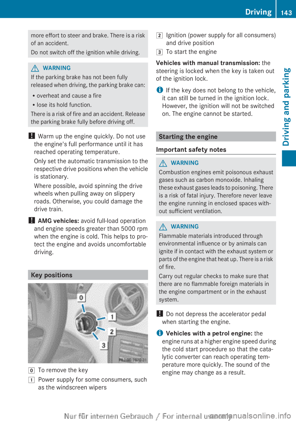
driving. Key positions
g
To remove the key
1 Power supply for some consumers, such
as the windscreen wipers 2
Ignition (power supply for all consumers)
and drive position
3 To start the engine
Vehicles with manual transmission: the
steering is locked when the key is taken out
of the ignition lock.
i If the key does not belong to the vehicle,
it can still be turned in the ignition lock.
However, the ignition will not be switched
on. The engine cannot be started. Starting the engine
Important safety notes G
WARNING
Combustion engines emit poisonous exhaust
gases such as carbon monoxide. Inhaling
these
exhaust gases leads to poisoning. There
is a risk of fatal injury. Therefore never leave
the engine running in enclosed spaces with-
out sufficient ventilation. G
WARNING
Flammable materials introduced through
environmental influence or by animals can
ignite
if in contact with the exhaust system or
parts of the engine that heat up. There is a risk
of fire.
Carry out regular checks to make sure that
there are no flammable foreign materials in
the engine compartment or in the exhaust
system.
! Do not depress the accelerator pedal
when starting the engine.
i Vehicles with a petrol engine: the
engine runs at a higher engine speed during
the cold start procedure so that the cata-
lytic converter can reach operating tem-
perature more quickly. The sound of the
engine may change as a result. Driving
143
Driving and parking Z
Page 166 of 356
Releasing
X
Pull handle :.
The red ! indicator lamp in the instru-
ment cluster goes out.
i You can only release the electric parking
brake when the key is in position 1 or 2 in
the ignition lock.
Applying automatically The electric parking brake is applied auto-
matically:
R
if DISTRONIC PLUS brings the vehicle to a
standstill (vehicles with automatic trans-
mission) or
R if
the HOLD function is keeping the vehicle
stationary.
In addition, at least one of the following con-
ditions must be fulfilled:
R the engine is switched off
R the driver's door is open and the seat belt
is not fastened
R there is a system malfunction
R the power supply is insufficient
R the vehicle is stationary for a lengthy
period.
The red ! indicator lamp in the instrument
cluster lights up.
i The electric parking brake is not automat-
ically applied if the engine is switched off
by the ECO start/stop function.
Releasing automatically i
The electric parking brake can only be
released automatically in vehicles with
automatic transmission.
The electric parking brake of your vehicle is
released
automatically when all of the follow-
ing conditions are fulfilled:
R the engine is running.
R the transmission is in position D or R.
R the seat belt is fastened.
R you depress the accelerator pedal. If the transmission is in position
R,
the tailgate
must be closed.
If your seat belt is not fastened, the following
conditions must be fulfilled to automatically
release the electric parking brake:
R the driver's door is closed.
R you have shifted out of transmission posi-
tion P or you have previously driven faster
than 3 km/h.
Emergency braking The vehicle can also be braked during an
emergency using the electric parking brake.
X
While driving, push handle :
of the electric
parking brake ( Y page 163).
i The vehicle is braked for as long as han-
dle : of the electric parking brake
pressed. The longer the electric parking
brake handle : is depressed, the greater
the braking force.
During braking:
R a warning tone sounds
R the Release parking brake message
appears
R the red ! indicator lamp in the instru-
ment cluster flashes
When
the vehicle has been braked to a stand-
still, the electric parking brake is engaged. Parking up the vehicle
If you leave the vehicle parked up for longer
than
four weeks, the battery may be damaged
by exhaustive discharging.
If you leave the vehicle parked up for longer
than six weeks, the vehicle may suffer dam-
age as a result of lack of use.
X Visit a qualified specialist workshop and
seek advice.
i You can obtain information about trickle
chargers from a qualified specialist work-
shop. 164
Parking
Driving and parking
Page 183 of 356
The electric parking brake secures the vehicle
automatically if the HOLD function is activa-
ted and:
R
the driver's door is open and the driver's
seat belt is unfastened
R the
engine is switched off, unless it is auto-
matically switched off by the ECO start/
stop function
R a system fault occurs
R the power supply is not sufficient
Vehicles with automatic transmission
If a fault occurs, then the transmission may
also be shifted into position P automatically.
Vehicles with manual transmission
The Brake immediately message can also
appear in the multifunction display.
X Immediately depress the brake pedal firmly
until
the warning message in the multifunc-
tion display goes out.
The HOLD function is deactivated.
A horn will sound at regular intervals if you
turn off the engine, take off your seat belt or
open the driver's door when the HOLD func-
tion is activated. The horn alerts you to the
fact that the HOLD function is still activated.
If you attempt to lock the vehicle, the tone
becomes louder. The vehicle cannot be
locked until you have deactivated the HOLD
function.
i Once you have switched off the engine,
you cannot restart it until you have deacti-
vated the HOLD function. RACE START
Important safety notes RACE START enables optimum acceleration
from a standing start. The precondition for
this is a suitable high-grip road surface.
Only
activate RACE START on dedicated race
circuits. i
RACE
START is only available in AMG vehi-
cles.
Activation conditions You can activate RACE START if:
R
the doors, the bonnet and the tailgate are
closed
R the
engine is running and the transmission,
traction control and engine are at operating
temperature
R SPORT handling mode is activated
(Y page 66)
R the steering wheel is in the straight-ahead
position.
R the vehicle is stationary and the brake
pedal is depressed (left foot)
R the transmission is in position D.
R drive program M is selected ( Y page 155).
Activating RACE START X
Depress the brake pedal with your left foot
and keep it depressed.
X Pull and hold both steering wheel gearshift
paddles.
X The RACE START Confirm: Paddle UP
Cancel: Paddle DOWN message appears
in the multifunction display.
X Release both steering wheel gearshift pad-
dles.
i If the activation conditions are no longer
fulfilled, RACE START is cancelled. The
RACE START not possible See Own‐
er's
Manual message appears in the mul-
tifunction display.
X To cancel:
pull the left steering wheel shift
paddle (Y page 156).
or
X To confirm: pull the right steering wheel
shift paddle
(Y page 156).
The RACE START available Depress
accelerator message appears in the mul-
tifunction display. Driving systems
181
Driving and parking Z
Page 208 of 356
X
Press the ball coupling in the direction of
the arrow until it engages behind the
bumper.
Indicator lamp ? goes out and the mes-
sage in the multifunction display disap-
pears. Trailer power supply
! You can connect accessories with a
power rating of up to 240 W to the perma-
nent
power supply and with a power rating
of up to 180 W to the power supply that is
switched on via the ignition lock.
The trailer battery may not be charged from
the power supply.
X To switch the connected power supply
on or off: turn the key in the ignition lock
to position 2 or 0 respectively.
When it leaves the factory, your vehicle's
trailer socket is equipped with a permanent
power supply and a power supply that is
switched on via the ignition lock.
The permanent power supply is supplied via
trailer socket pin 9.
The power supply that is switched on via the
ignition lock is supplied via trailer socket pin
10.
The trailer's permanent power supply is
switched
off in the event of low vehicle supply
voltage and after six hours at the latest.
You can find more information about instal-
ling the trailer electrics at a qualified special-
ist workshop. Bulb failure indicator for LED lamps
i If LED lamps are fitted in the trailer, an
error message may appear in the multi-
function
display even if there is no fault. The
reason for the error message could be that
the current has fallen below the minimum
of 50 mA. To ensure reliable operation of the bulb failure
indicator,
each LED chain in the trailer lighting
must be guaranteed a minimum current of
50 mA. Trailer with 7-pin connector
General notes Trailer with 7-pin connector: you can con-
nect
to the 13-pin socket on the ball coupling
using an adapter or, if necessary, an adapter
cable. Both can be obtained at a qualified
specialist workshop.
Fitting the adapter !
Make sure that there is sufficient cable
play so that the cable cannot become
detached when cornering.
! Remove the installed adapter cable
before folding in the ball coupling. Other-
wise, damage may occur to the rear
bumper and the adapter cable. X
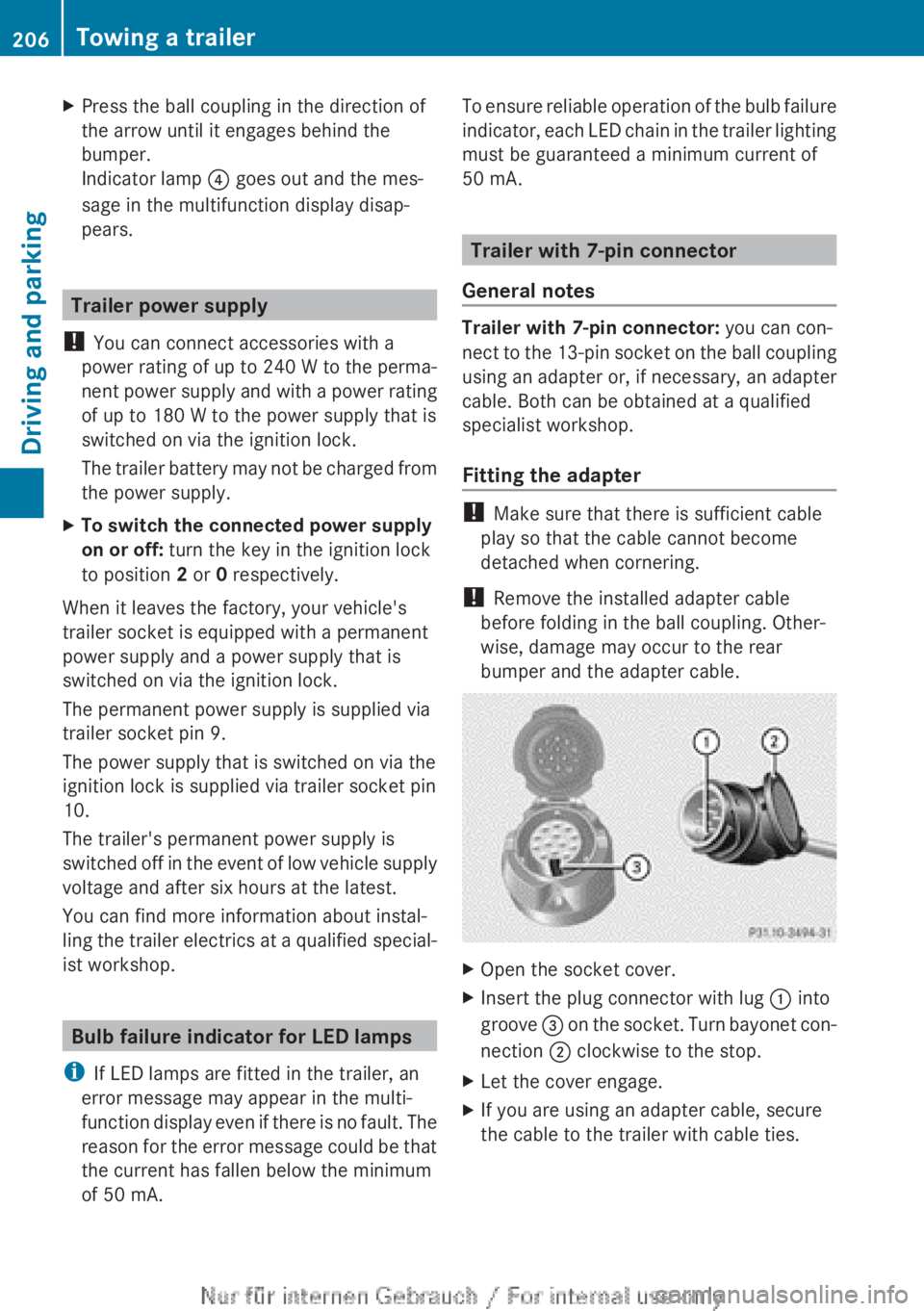
Open the socket cover.
X Insert the plug connector with lug : into
groove =
on the socket. Turn bayonet con-
nection ; clockwise to the stop.
X Let the cover engage.
X If you are using an adapter cable, secure
the cable to the trailer with cable ties.206
Towing a trailer
Driving and parking
Page 308 of 356
The battery and the cover of the positive
terminal
clamp must be fitted securely dur-
ing operation.
Comply with safety precautions and take pro-
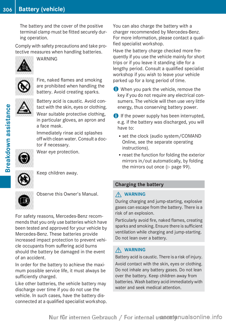
tective measures when handling batteries. WARNING
Fire, naked flames and smoking
are prohibited when handling the
battery. Avoid creating sparks.
Battery acid is caustic. Avoid con-
tact
with the skin, eyes or clothing.
Wear suitable protective clothing,
in particular gloves, an apron and
a face mask.
Immediately rinse acid splashes
off with clean water. Consult a doc-
tor if necessary. Wear eye protection.
Keep children away.
Observe this Owner's Manual.
For safety reasons, Mercedes-Benz recom-
mends
that you only use batteries which have
been tested and approved for your vehicle by
Mercedes-Benz. These batteries provide
increased impact protection to prevent vehi-
cle occupants from suffering acid burns
should the battery be damaged in the event
of an accident.
In order for the battery to achieve the maxi-
mum possible service life, it must always be
sufficiently charged.
Like other batteries, the vehicle battery may
discharge over time if you do not use the
vehicle. In such cases, have the battery dis-
connected at a qualified specialist workshop. You can also charge the battery with a
charger recommended by Mercedes-Benz.
For
more information, please contact a quali-
fied specialist workshop.
Have the battery charge checked more fre-
quently if you use the vehicle mainly for short
trips or if you leave it standing idle for a
lengthy period. Consult a qualified specialist
workshop if you wish to leave your vehicle
parked up for a long period of time.
i When you park the vehicle, remove the
key if you do not require any electrical con-
sumers. The vehicle will then use very little
energy, thus conserving battery power.
i If the power supply has been interrupted,
e.g. if the battery was discharged, you will
have to:
R set the clock (audio system/COMAND
Online, see the separate operating
instructions).
R reset the function for folding the exterior
mirrors in/out automatically, by folding
the mirrors out once ( Y page 99). Charging the battery
G
WARNING
During charging and jump-starting, explosive
gases
can escape from the battery. There is a
risk of an explosion.
Particularly avoid fire, naked flames, creating
sparks and smoking. Ensure there is sufficient
ventilation while charging and jump-starting.
Do not lean over a battery. G
WARNING
Battery acid is caustic. There is a risk of injury.
Avoid
contact with the skin, eyes or clothing.
Do not inhale any battery gases. Do not lean
over the battery. Keep children away from
batteries. Wash battery acid immediately with
water and seek medical attention. 306
Battery (vehicle)
Breakdown assistance
Page 312 of 356
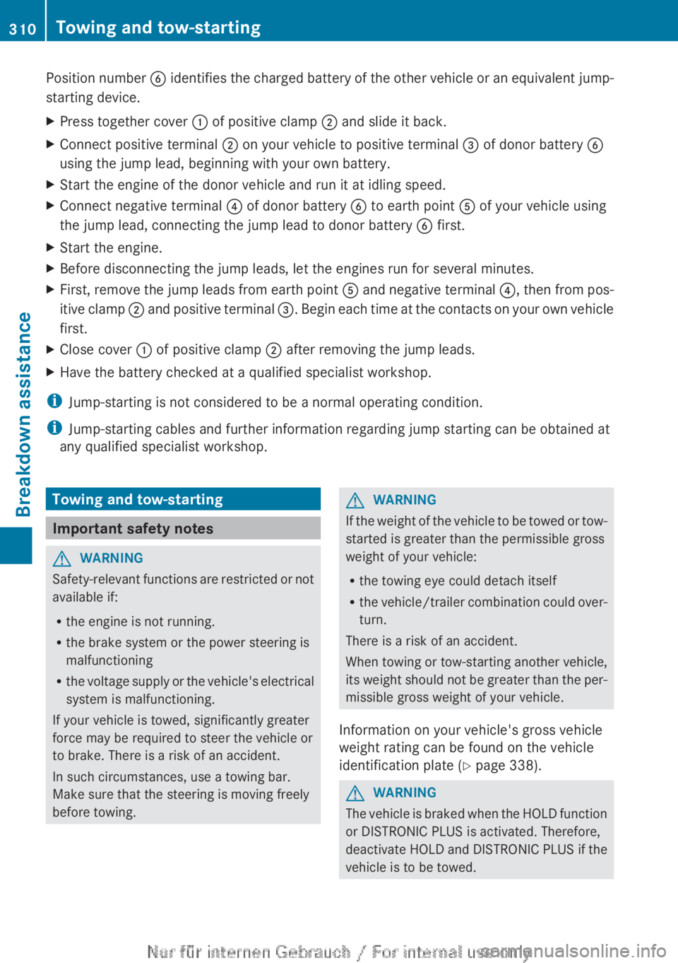
Position number
B identifies the charged battery of the other vehicle or an equivalent jump-
starting device.
X Press together cover : of positive clamp ; and slide it back.
X Connect positive terminal ; on your vehicle to positive terminal = of donor battery B
using the jump lead, beginning with your own battery.
X Start the engine of the donor vehicle and run it at idling speed.
X Connect negative terminal ? of donor battery B to earth point A of your vehicle using
the jump lead, connecting the jump lead to donor battery B first.
X Start the engine.
X Before disconnecting the jump leads, let the engines run for several minutes.
X First, remove the jump leads from earth point A
and negative terminal ?, then from pos-
itive clamp ; and positive terminal =. Begin each time at the contacts on your own vehicle
first.
X Close cover : of positive clamp ; after removing the jump leads.
X Have the battery checked at a qualified specialist workshop.
i Jump-starting is not considered to be a normal operating condition.
i Jump-starting cables and further information regarding jump starting can be obtained at
any qualified specialist workshop. Towing and tow-starting
Important safety notes
G
WARNING
Safety-relevant functions are restricted or not
available if:
R the engine is not running.
R the brake system or the power steering is
malfunctioning
R the
voltage supply or the vehicle's electrical
system is malfunctioning.
If your vehicle is towed, significantly greater
force may be required to steer the vehicle or
to brake. There is a risk of an accident.
In such circumstances, use a towing bar.
Make sure that the steering is moving freely
before towing. G
WARNING
If the weight of the vehicle to be towed or tow-
started is greater than the permissible gross
weight of your vehicle:
R the towing eye could detach itself
R the
vehicle/trailer combination could over-
turn.
There is a risk of an accident.
When towing or tow-starting another vehicle,
its weight should not be greater than the per-
missible gross weight of your vehicle.
Information on your vehicle's gross vehicle
weight rating can be found on the vehicle
identification plate ( Y page 338). G
WARNING
The vehicle is braked when the HOLD function
or DISTRONIC PLUS is activated. Therefore,
deactivate
HOLD and DISTRONIC PLUS if the
vehicle is to be towed. 310
Towing and tow-starting
Breakdown assistance
Page 339 of 356
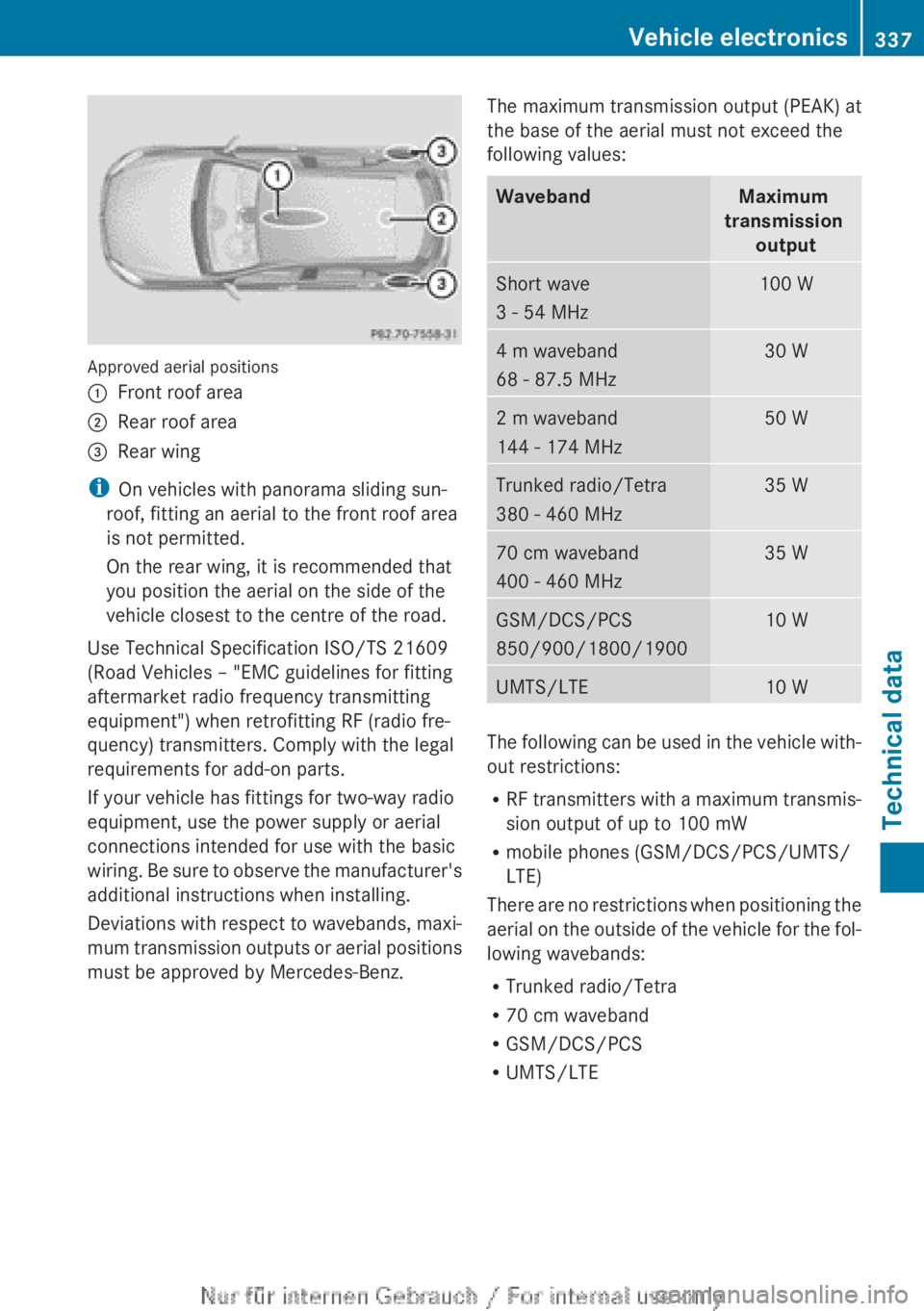
Approved aerial positions
:
Front roof area
; Rear roof area
= Rear wing
i On vehicles with panorama sliding sun-
roof, fitting an aerial to the front roof area
is not permitted.
On the rear wing, it is recommended that
you position the aerial on the side of the
vehicle closest to the centre of the road.
Use Technical Specification ISO/TS 21609
(Road Vehicles – "EMC guidelines for fitting
aftermarket radio frequency transmitting
equipment") when retrofitting RF (radio fre-
quency) transmitters. Comply with the legal
requirements for add-on parts.
If your vehicle has fittings for two-way radio
equipment, use the power supply or aerial
connections intended for use with the basic
wiring.
Be sure to observe the manufacturer's
additional instructions when installing.
Deviations with respect to wavebands, maxi-
mum transmission outputs or aerial positions
must be approved by Mercedes-Benz. The maximum transmission output (PEAK) at
the base of the aerial must not exceed the
following values: Waveband Maximum
transmission output Short wave
3 - 54 MHz 100 W
4 m waveband
68 - 87.5 MHz 30 W
2 m waveband
144 - 174 MHz 50 W
Trunked radio/Tetra
380 - 460 MHz 35 W
70 cm waveband
400 - 460 MHz 35 W
GSM/DCS/PCS
850/900/1800/1900 10 W
UMTS/LTE 10 W
The following can be used in the vehicle with-
out restrictions:
R
RF
transmitters with a maximum transmis-
sion output of up to 100 mW
R mobile phones (GSM/DCS/PCS/UMTS/
LTE)
There are no restrictions when positioning the
aerial on the outside of the vehicle for the fol-
lowing wavebands:
R Trunked radio/Tetra
R 70 cm waveband
R GSM/DCS/PCS
R UMTS/LTE Vehicle electronics
337
Technical data Z