turn signal MERCEDES-BENZ AMG GT COUPE 2018 Owner's Manual
[x] Cancel search | Manufacturer: MERCEDES-BENZ, Model Year: 2018, Model line: AMG GT COUPE, Model: MERCEDES-BENZ AMG GT COUPE 2018Pages: 294, PDF Size: 4.76 MB
Page 9 of 294
Charge-air pressure (on-board
computer).......................................... 165
Child
Restraint system .............................. 55
Child seat
Forward-facing restraint system ...... 56
On the front-passenger seat ............ 56
Rearward-facing restraint system .... 56
Children
Special seat belt retractor .............. .55
Children in the vehicle
Important safety notes .................... 54
Cigarette lighter ................................ 218
Cleaning
Mirror turn signal .......................... .242
Climate control
Air-recirculation mode ................... 102
Automatic climate control (dual-
zone) ................................................ 98
Controlling automatically ...............1 00
Cooling with air dehumidification ..... 99
Cooling with air dehumidification
(multimedia system) ......................2 08
Defrosting the windows ................. 101
Defrosting the windshield .............. 101
ECO start/stop function (3-zone
automatic climate control) ...............9 9
General notes .................................. 98
Indicator lamp ................................ 100
Information about using auto-
matic climate control ...................... .99
Overview ........................................2 08
Overview of systems ........................ 98
Problem with the rear wi ndow
defroster ........................................ 102
Probl
ems with cooling with air
dehumidification ............................ 100
Refrigerant ..................................... 288
Refrigerant filling capacity ............. 288
Setting the air distribution ............. 100
Setting the air vents ......................1 02
Setting the airflow ......................... 101
Setting the climate mode (multi-
media system) ............................... 208
Setting the temperature ................ 100
Switching air-recirculation mode
on/off ............................................ 102
Switching on/off .............................. 99 Switching the rear window
defroster on/off ............................ 101
Switching the synchronization
function on and off ........................ 101
Synchronization function (multi-
media system) ............................... 209
Climate control settings
Multimedia system ........................ 208
Climate control system
Climate control (3-zone automatic
climate control) ................................ 99
Cockpit
Overview .......................................... 33
Code for Apps
see QR code
COMAND display
Cleaning ......................................... 243
Combination switch ............................ 92
Connecting a USB device
see also Digital Operator's Man-
ual ..................................................2 04
Consumption statistics (on-board
computer) .......................................... 157
Controller ...........................................2 05
Convenience closing feature .............. 77
Convenience opening
With the SmartKey ........................... 76
Coolant (engine)
Checking the level ......................... 236
Display message ............................ 181
Filling capacity ............................... 287
Important safety notes .................. 287
Temperature display in the instru-
ment cluster .................................. 154
Warning lamp ..................... ............ 199
C
ooling
see Climate control
Copyright ............................................. 32
Cornering light function
Display message ............................ 180
Cruise control
Cruise control lever ....................... 130
Deactivating ................................... 131
Display message ............................ 185
General notes ................................ 129
Setting a speed .............................. 131
Index7
Page 14 of 294
I
Ignition keysee SmartKey
Ignition lock
see Key positions
Immobilizer .......................................... 63
Indicator lamps
see Warning and indicator lamps
Indicators
see Turn signals
Inspection
see ASSYST PLUS
Instrument cluster
Overview .......................................... 34
Warning and indicator lamps .......... .34
Instrument cluster lighting .............. 164
Interior lighting
Automatic control ............................ 95
Overview .......................................... 94
Reading lamp .................................. .94
Setting the brightness of the dis-
play/switch (on-board computer) .. 164
iPod
®
see also Digital Operator's Man-
ual .................................................. 204
J
Jack Using ............................................. 277
Jump starting (engine) ...................... 251
K
Key positions
SmartKey ....................................... 106
Start/Stop button .......................... 105
KEYLESS-GO
Convenience closing feature ............ 77
Deactivation ..................................... 66
Locking ............................................ 66
Start function ................................... 66
Unlocking ......................................... 66
KEYLESS-GO start function
Start/Stop button .......................... 105
Kickdown
Driving tips .................................... 115
Knee bag .............................................. 45
L
Lamps
see Warning and indicator lamps
Lane detection (automatic)
see Lane Keeping Assist
Lane Keeping Assist
Activating/deactivating (on-
board computer) ............................ 164
Display message ............................ 184
Function/information .................... 152
Lane Tracking package ..................... 150
Lap time (RACETIMER) ...................... 167
License plate lamp (display mes-
sage) ................................................... 180
Light sensor (display message) ....... 180
Lights
Automatic headlamp mode .............. 91
Fogged up headlamps ...................... 94
Hazard warning lamps ..................... 93
High beam flasher ............................ 92
High-beam headlamps ..................... 92
Light switch ..................................... 91
Low-beam headlamps ...................... 92
Parking lamps .................................. 92
Rear fog lamp .................................. 92
Setting exterior lighting ................... 91
Setting the brightness of the dis-
play/switch (on-board computer) .. 164
Standing lamps ................................ 92
Switching the daytime running
lamps on/off (on-board com-
puter) ............................................. 164
Turn signals ..................................... 92
see Interior lighting
Loading guidelines ............................ 213
Locking (doors)
Automatic ........................................ 72
Emergency locking ........................... 72
From inside (central locking but-
ton) .................................................. 71
see KEYLESS-GO
Locking centrally
see Central locking
Low-beam headlamps
Display message ............................ 180
Switching on/off .............................. 92
12Index
Page 15 of 294
Lubricant additivessee Additives (engine oil)
M
M button ............................................ .116
M+S tires ............................................ 260
Malfunction message
see Display messages
Manual drive program
Activating ....................................... 117
Changing gear ............................... 118
Deactivating ................................... 118
General notes ................................ 117
Manual mode
Activating ....................................... 118
Deactivating ................................... 119
General notes ................................ 118
Matte finish (cleaning instruc-
tions) ..................................................2 41
mbrace
Call priority ....................................2 22
Display message ............................ 175
Downloading destinations
(COMAND) ..................................... 222
Downloading routes ....................... 225
Emergency call .............................. 220
General notes ................................ 219
Geo fencing ................................... 225
Info call button .............................. 221
Locating a stolen vehicle ...............2 24
Remote fault diagnosis .................. 224
Remote vehicle locking .................. 223
Roadside assistance button ........... 221
Search & Send ............................... 223
Self-test ......................................... 219
Speed alert .................................... 225
System .......................................... 219
Triggering the vehicle alarm ........... 225
Vehicle remote unlocking .............. 223
Mechanical key
Function/notes ................................ 67
General notes .................................. 67
Inserting .......................................... 67
Locking vehicle ................................ 72
Removing ......................................... 67
Unlocking the driver's door .............. 72 Media Interface
see Digital Operator's Manual
Memory card (audio) ......................... 160
Memory function
Seats, steering wheel, exterior
mirrors ............................................. 89
Mercedes me connect
Change of vehicle ............................ 32
Data protection ................................ 32
Website ............................................ 31
Merce
des-Benz Intelligent Drive
Distance Pilot DISTRONIC ............. 131
Message memory (on-board com-
puter) .................................................. 169
Messages
see Display messages
see Warning and indicator lamps
Mirror turn signal
Cleaning ......................................... 242
Mirrors
see Exterior mirrors
see Rear-view mirror
see Vanity mirror
Mobile phone
Connecting (device manager) ........ 210
Frequencies ................................... 282
Installation ..................................... 282
Menu (on-board computer) ............ 161
Transmission output (maximum) .... 282
Model type
see Vehicle identification plate
Modifying the programming
(SmartKey) ........................................... 67
Mounting wheels
Lowering the vehicle ...................... 280
Mounting a new wheel ................... 279
Preparing the vehicle ..................... 277
Raising the vehicle ......................... 277
Removing a wheel .......................... 279
Securing the vehicle against roll-
ing away ........................................ 277
MP3
Operation ....................................... 160
see also Digital Operator's Man-
ual .................................................. 204
Multifunction display
Function/notes ............................. 156
Index13
Page 22 of 294
Replacing...................................... .276
Service life ..................................... 259
Sidewall (definition) ....................... 275
Speed rating (definition) ................ 275
Storing ...........................................2 77
Structure and characteristics
(definition) ..................................... 274
Summer tires in winter .................. 260
Temperature .................................. 270
TIN (Tire Identification Number)
(definition) ..................................... 276
Tire bead (definition) ......................2 75
Tire pressure (definition) ................ 275
Tire pressures (recommended) ...... 274
Tire size (data) ............................... 280
Tire size designation, load-bearing
capacity, speed rating .................... 271
Tire tread ....................................... 259
Tire tread (definition) ..................... 275
Total load limit (definition) ............. 276
Traction ......................................... 270
Traction (definition) ....................... 276
Tread wear ..................................... 270
Uniform Tire Quality Grading
Standards ...................................... 269
Uniform Tire Quality Grading
Standards (definition) .................... 274
Wear indicator (definition) ............. 276
Wheel and tire combination ........... 280
Wheel rim (definition) .................... 274
see Flat tire
Tool
see Vehicle tool kit
Touchpad
Changing the station/music
track .............................................. 207
Character suggestions ................... 206
Deleting characters ....................... 206
Entering a space ............................ 206
Entering characters ....................... 206
Gesture control .............................. 206
Handwriting recognition ................ 206
Operating the touchpad ................. 206
Overview ........................................ 206
Quick access for Audio .................. 207
Switching ....................................... 206
Switching input line ....................... 206 Tow-starting
Emergency engine starting ............ 256
To
wing away
Important safety guidelines ........... 254
Installing the towing eye ................ 255
Removing the towing eye ............... 255
Transporting the vehicle ................ 256
With both axles on the ground ....... 255
Towing eye ......................................... 245
Traction system
see ETS (Electronic Traction System)
Traffic reports
see also Digital Operator's Man-
ual .................................................. 204
Transmission
Driving tips .................................... 115
Selector lever ................................ 112
see Automatic transmission
Transmission position display ......... 114
Transmission positions
General notes ................................ 112
Overview ........................................ 113
Transporting the vehicle .................. 256
Trim pieces (cleaning instruc-
tions) .................................................. 243
Trip computer (on-board com-
puter) .................................................. 157
Trip odometer
Calling up ....................................... 156
Resetting (on-board computer) ...... 157
Trunk load (maximum) ...................... 288
Trunk partition .................................. 215
Turn signals
Display message ............................ 180
Switching on/off .............................. 92
Two-way radio
Frequencies ................................... 282
Installation ..................................... 282
Transmission output (maximum) .... 282
Type identification plate
see Vehicle identification plate
U
UnlockingEmergency unlocking ....................... 72
From inside the vehicle (central
unlocking button) ............................. 71
20Index
Page 36 of 294
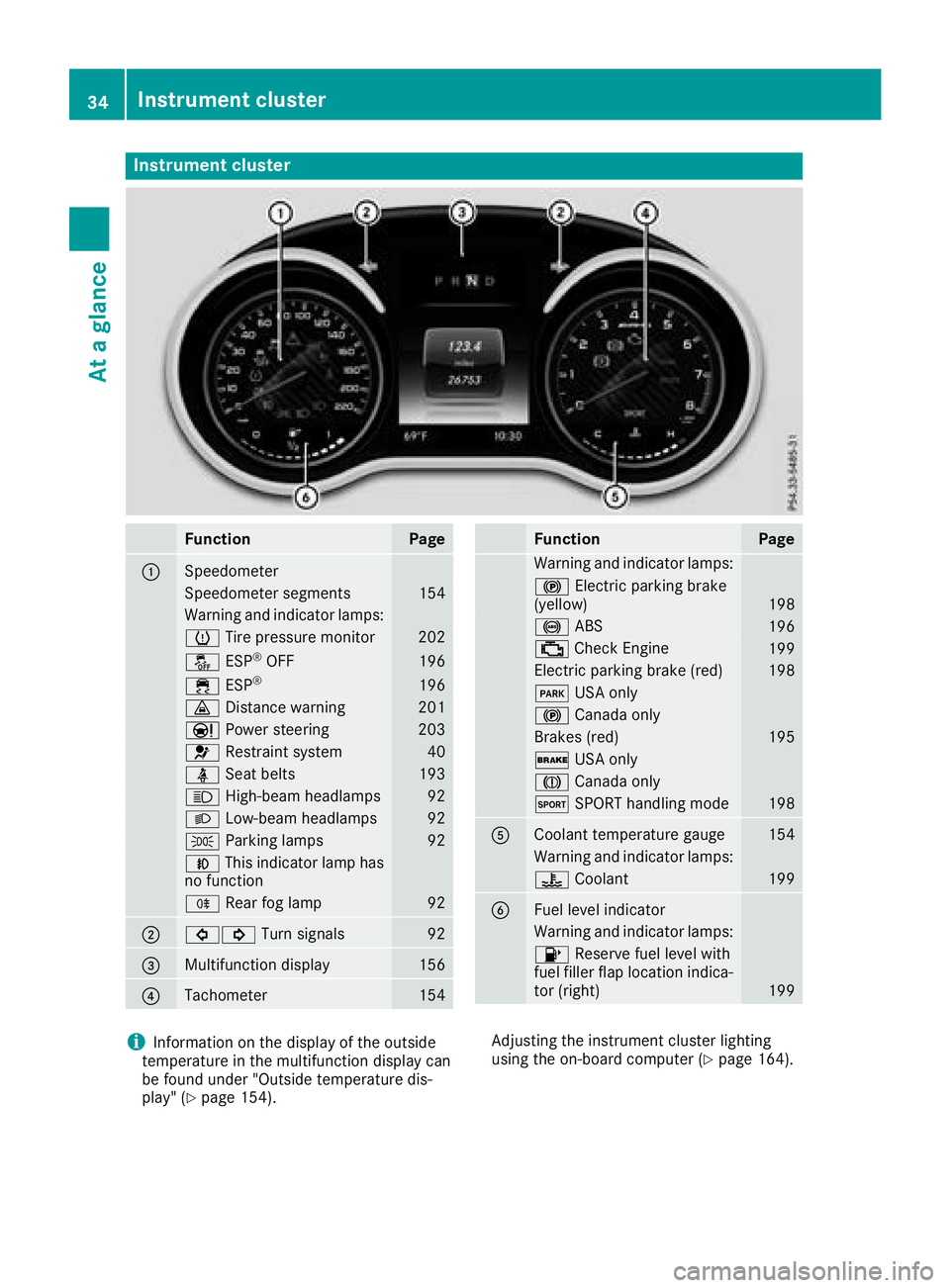
Instrument cluster
FunctionPage
:Speedometer
Speedometer segments154
Warning and indicator lamps:
h Tirepressur emonitor20 2
å ESP®OF F196
÷ ESP®19 6
· Distanc ewarning20 1
Ð Powersteering20 3
6 Restrain tsystem40
ü Seat belt s193
K High-beam headlamps92
LLow-beam headlamps92
TParking lamp s92
NThis indicator lamp has
no function
R Rear fog lamp92
;#! Turn signals92
=Multifunction display156
?Tachometer154
FunctionPag e
Warning and indicator lamps:
! Electric parking brak e
(yellow)19 8
! ABS196
; CheckEngin e199
Electric parking brak e(red)19 8
F USAonly
! Canad aonly
Brake s(red)19 5
$ USAonly
J Canad aonly
M SPORT handlin gmod e198
ACoolan ttemperature gauge15 4
Warning and indicator lamps:
? Coolan t199
BFue llevel indicator
Warning and indicator lamps:
8 Reserve fuel level wit h
fuel filler flap location indica-
to r(right )
199
iInformation on th edisplay of th eoutside
temperature in th emultifunction display can
be foun dunder "Outside temperature dis-
play" (
Ypage 154). Adjusting th
einstrumen tcluste rlighting
usin gth eon-board computer (
Ypage 164).
34Instrument cluster
At a glance
Page 67 of 294
SmartKey
Important safety notes
GWARNING
If children are left unsupervised in the vehicle,
they could:
Ropen the doors, thus endangering other
people or road users.
Rget out and disrupt traffic.
Roperate the vehicle's equipment.
Additionally, children could set the vehicle in
motion if, for example, they:
Rrelease the parking brake.
Rshifting the automatic transmission out of
park position P
RStart the engine.
There is a risk of an accident and injury.
When leaving the vehicle, always take the
SmartKey with you and lock the vehicle. Never
leave children or animals unattended in the
vehicle. Always keep the SmartKey out of
reach of children.
GWARNING
If you attach heavy or large objects to the
SmartKey, the SmartKey could be uninten-
tionally turned in the ignition lock. This could
cause the engine to be switched off. There is a risk of an accident.
Do not attach any heavy or large objects to the
SmartKey. Remove any bulky key rings before
inserting the SmartKey into the ignition lock.
!Keep the SmartKey away from strong mag-
netic fields. Otherwise, the remote control
function could be affected.
Strong magnetic fields can occur in the vicin-
ity of powerful electrical installations.
Do not keep the SmartKey:
Rwith electronic devices, e.g. a mobile phone
or another SmartKey
Rwith metallic objects, e.g. coins or metal foil
Rinside metallic objects, e.g. a metal case
This can affect the functionality of the Smart-
Key. Vehicles with KEYLESS-GO start function:
do
not keep the SmartKey on the cargo compart-
ment cover or in the cargo compartment. Oth-
erwise, the SmartKey may not be detected, e.g.
when starting the engine using the Start/Stop
button.
A brief radio connection between the vehicle
and the SmartKey determines whether a valid
SmartKey is in, or in the direct vicinity of, the
vehicle. This occurs, for example:
Rwhen starting the engine
Rwhile driving
Rwhen using the tailgate unlocking sensor
Rwhen the external door handles are touched
Rduring convenience closing
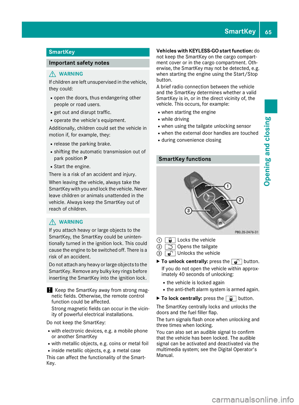
SmartKey functions
:& Locks the vehicle
;FOpens the tailgate
=%Unlocks the vehicle
XTo unlock centrally: press the%button.
If you do not open the vehicle within approx-
imately 40 seconds of unlocking:
Rthe vehicle is locked again
Rthe anti-theft alarm system is armed again.
XTo lock centrally: press the&button.
The SmartKey centrally locks and unlocks the
doors and the fuel filler flap.
The turn signals flash once when unlocking and
three times when locking.
You can also set an audible signal to confirm
that the vehicle has been locked. The audible
signal can be activated and deactivated via the
multimedia system; see the Digital Operator's
Manual.
SmartKey65
Opening and closing
Z
Page 94 of 294
The daytime running lamps improve the visibility
of your vehicle during the day. Here, theDay‐
time Running Lightsfunction must be
switched on via the on-board computer
(
Ypage 164).
If the engine is running and you turn the light
switch to the TorL position, the manual
settings take precedence over the daytime run-
ning lamps.
Low-beam headlamps
GWARNING
When the light switch is set to Ã, the low-
beam headlamps may not be switched on
automatically if there is fog, snow or other
causes of poor visibility due to the weather
conditions such as spray. There is a risk of an
accident.
In such situations, turn the light switch to
L.
When the ignition is switched on and the light
switch is in the Lposition, the parking lamps
and low-beam headlamps are switched on even
if the light sensor does not sense dark condi-
tions. This is a particularly useful function in the
event of rain and fog.
XTo switch on the low-beam headlamps:
select key position 2with the Start/Stop
button or start the engine.
XTurn the light switch to the Lposition.
The green Lindicator lamp in the instru-
ment cluster lights up.
Rear fog lamp
The rear fog lamp improves visibility of your
vehicle for the traffic behind in the event of thick
fog. You must observe the legal requirements
for the country in which you are currently driving when operating the rear fog lamp.
XTo switch on the rear fog lamp: select key
position 2with the Start/Stop button or
start the engine.
XTurn the light switch to the LorÃ
position.
XPress the Rbutton.
The yellow Rindicator lamp in the instru-
ment cluster lights up.
XTo switch off the rear fog lamp: press the
R button.
The yellow Rindicator lamp in the instru-
ment cluster goes out.
Parking lamps
!If the battery charge is very low, the parking
lamps or standing lamps are automatically
switched off to enable the next engine start.
Always park your vehicle safely and in a well lit
area, in accordance with the relevant legal
stipulations. Avoid using the Tparking
lamps over a period of several hours. If pos-
sible, switch on the right-hand Xor left-
hand W standing lamps.
XTo switch on the parking lamps: turn the
light switch to the Tposition.
The green Tindicator lamp in the instru-
ment cluster lights up.
Standing lamps
Switching on the standing lamps ensures the
correspondin g side of the vehicle is illuminated.
XTo switch on the standing lamps: switch off
the engine with the Start/Stop button.
XTurn the light switch to the Wposition (left-
hand side of the vehicle) or Xposition
(right-hand side of the vehicle).
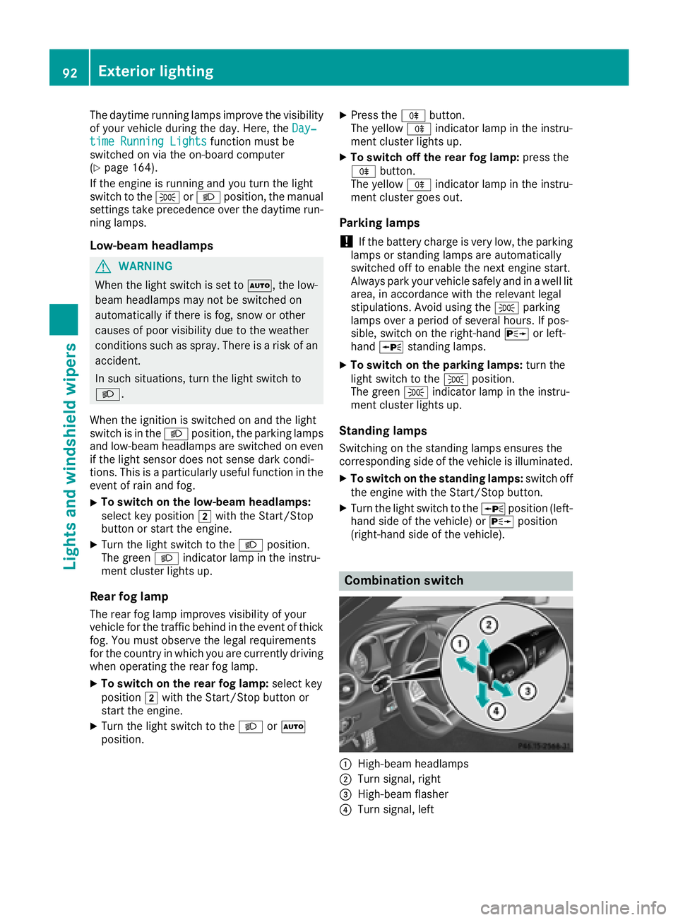
Combination switch
:High-beam headlamps
;Turn signal, right
=High-beam flasher
?Turn signal, left
92Exterior lighting
Lights and windshield wipers
Page 95 of 294
XTo indicate briefly:press the combination
switch briefly to the pressure point in the
direction of arrow ;or?.
The corresponding turn signal flashes three
times.
XTo indicate: press the combination switch
beyond the pressure point in the direction of
arrow ;or?.
XTo switch on the high-beam headlamps:
select key position 2with the Start/Stop
button or start the engine.
XTurn the light switch to the LorÃ
position.
XPress the combination switch beyond the
pressure point in the direction of arrow :.
In the Ãposition, the high-beam head-
lamps are only switched on when it is dark and
the engine is running.
The K indicator lamp in the instrument
cluster lights up when the high-beam head-
lamps are switched on.
XTo switch off the high-beam headlamps:
move the combination switch back to its nor-
mal position.
The K indicator lamp in the instrument
cluster goes out.
Vehicles with Adaptive Highbeam Assist: when
Adaptive Highbeam Assist is active, it controls
switching on/off of the high-beam headlamps
(
Ypage 93).
XTo switch on the high-beam flasher: pull
the combination switch in the direction of
arrow =.
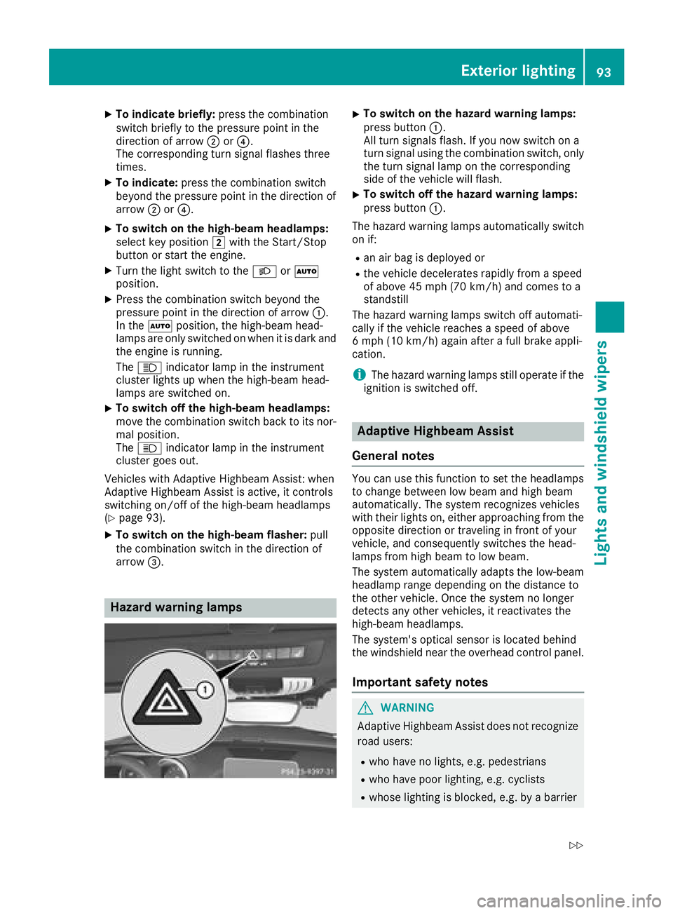
Hazard warning lamps
XTo switch on the hazard warning lamps:
press button :.
All turn signals flash. If you now switch on a
turn signal using the combination switch, only
the turn signal lamp on the corresponding
side of the vehicle will flash.
XTo switch off the hazard warning lamps:
press button :.
The hazard warning lamps automatically switch
on if:
Ran air bag is deployed or
Rthe vehicle decelerates rapidly from a speed
of above 45 mph (70 km/h) and comes to a
standstill
The hazard warning lamps switch off automati-
cally if the vehicle reaches a speed of above
6 mph (10 km/h) again after a full brake appli-
cation.
iThe hazard warning lamps still operate if the
ignition is switched off.
Adaptive Highbeam Assist
General notes
You can use this function to set the headlamps
to change between low beam and high beam
automatically. The system recognizes vehicles
with their lights on, either approaching from the
opposite direction or traveling in front of your
vehicle, and consequently switches the head-
lamps from high beam to low beam.
The system automatically adapts the low-beam
headlamp range depending on the distance to
the other vehicle. Once the system no longer
detects any other vehicles, it reactivates the
high-beam headlamps.
The system's optical sensor is located behind
the windshield near the overhead control panel.
Important safety notes
GWARNING
Adaptive Highbeam Assist does not recognize
road users:
Rwho have no lights, e.g. pedestrians
Rwho have poor lighting, e.g. cyclists
Rwhose lighting is blocked, e.g. by a barrier
Exterior lighting93
Lights and windshield wiper s
Z
Page 137 of 294
Changing lanes
If you change to the overtaking lane, Distance
Pilot DISTRONIC supports you if:
Ryou are driving at a speed greater than
45 mph (70 km/h)
Ryou switch on the appropriate turn signal
RDistance Pilot DISTRONIC does not currently
detect a danger of collision
If these conditions are fulfilled, your vehicle is
accelerated. Acceleration will be interrupted if
changing lanes takes too long or if the distance
between your vehicle and the vehicle in front
becomes too small.
iWhen you change lanes, Distance Pilot
DISTRONIC monitors the left lane.
Stopping
GWARNING
If you leave the vehicle when it is only being
braked by Distance Pilot DISTRONIC, it could
roll away if:
Rthere is a malfunction in the system or in
the voltage supply.
RDistance Pilot DISTRONIC is switched off
using the cruise control lever, e.g. by a vehi-
cle occupant or from outside the vehicle
Rthe electrical system in the engine com-
partment, the battery or the fuses are tam-
pered with.
Rthe battery is disconnected
Rthe vehicle is accelerated, e.g. by a vehicle
occupant.
There is a risk of an accident.
Before leaving the vehicle, always deactivate
Distance Pilot DISTRONIC and secure the
vehicle against rolling away.
Further information on deactivating Distance
Pilot DISTRONIC (
Ypage 136).
If Distance Pilot DISTRONIC detects that the
vehicle in front is stopping, it brakes your vehicle
to a stop.
Once your vehicle is stationary, it remains sta-
tionary and you do not need to depress the
brake.
iAfter a time, the electric parking brake
secures the vehicle and relieves the service
brake.
iDepending on the specified minimum dis-
tance, your vehicle will come to a standstill at
a sufficient distance behind the vehicle in
front. The specified minimum distance is set
using the control on the cruise control lever.
The elect
ric parking brake secures the vehicle
automatically if Distance Pilot DISTRONIC is
activated when the vehicle is stationary and:
Rthe driver's seat belt is not fastened and the
driver's door is open
Rthe engine is switched off, unless it is auto-
matically switched off by the ECO start/stop
function
Ra system malfunction occurs
Rthe power supply is insufficient
If a malfunction occurs, the transmission may
also shift to position jautomatically.
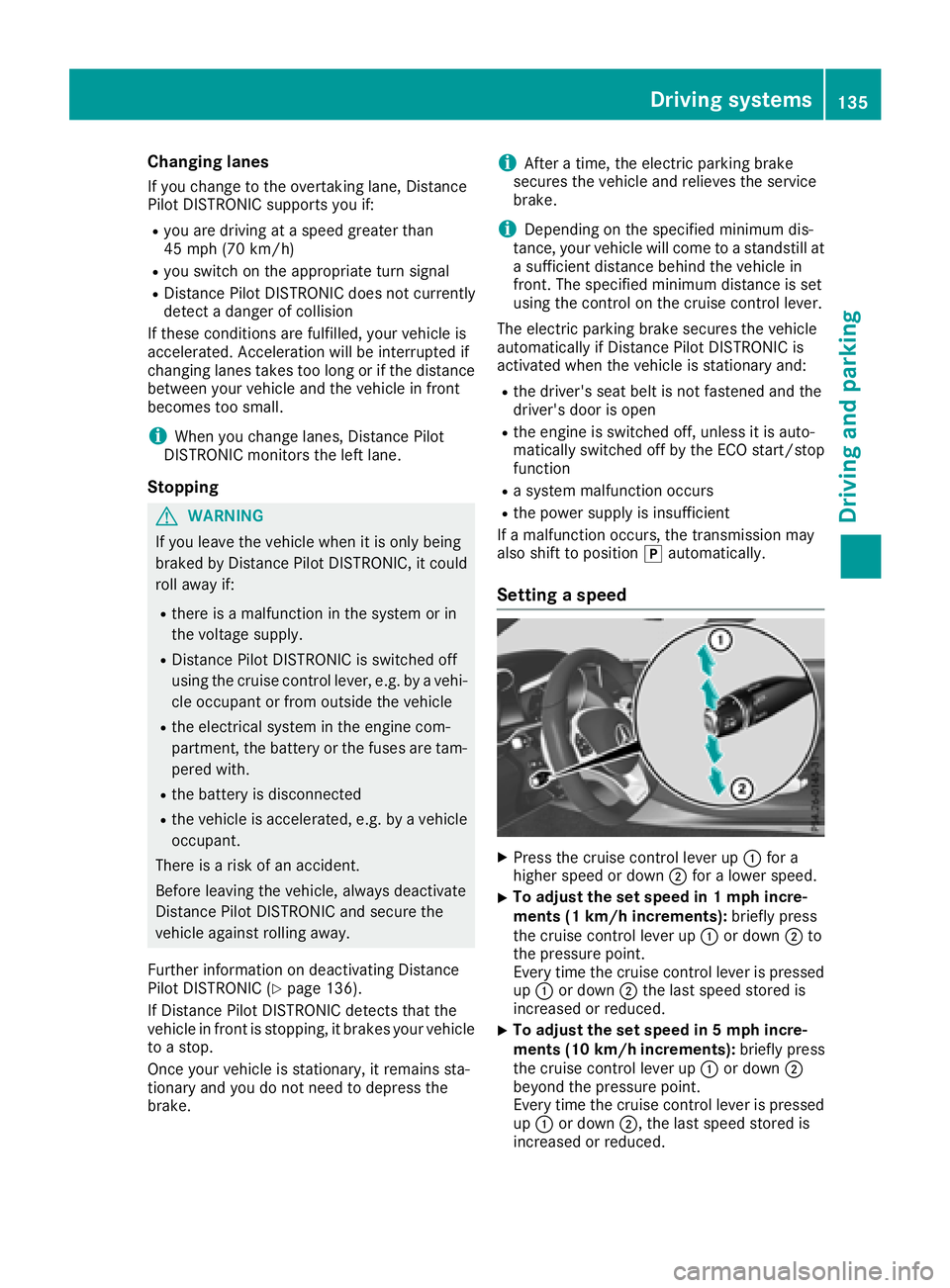
Setting a speed
XPress the cruise control lever up :for a
higher speed or down ;for a lower speed.
XTo adjust the set speed in 1 mph incre-
ments (1 km/h increments): briefly press
the cruise control lever up :or down ;to
the pressure point.
Every time the cruise control lever is pressed
up : or down ;the last speed stored is
increased or reduced.
XTo adjust the set speed in 5 mph incre-
ments (10 km/h increments): briefly press
the cruise control lever up :or down ;
beyond the pressure point.
Every time the cruise control lever is pressed
up : or down ;, the last speed stored is
increased or reduced.
Driving systems135
Driving and parking
Z
Page 152 of 294
This will only happen if ATTENTION ASSIST still
detects typical indicators of fatigue or increas-
ing lapses in concentration.
If a warning is output in the multifunction dis-
play, a service station search is performed in
COMAND. You can select a service station and
navigation to this service station will then begin.
This function can be activated and deactivated
in COMAND.
Lane Tracking package
General notes
The Lane Tracking package consists of Blind
Spot Assist (Ypage 150) and Lane Keeping
Assist (Ypage 152).
Blind Spot Assist
General notes
Blind Spot Assist monitors the areas on either
side of the vehicle that are not visible to the
driver with two lateral, rear-facing radar sen-
sors. A warning display in the exterior mirrors
draws your attention to vehicles detected in the
monitored area. If you then switch on the cor-
responding turn signal to change lane, you will
also receive an optical and audible warning.
Blind Spot Assist supports you from a speed of
approximately 20 mph (30 km/h).
Important safety notes
GWARNING
Blind Spot Assist does not react to:
Rvehicles overtaken too closely on the side,
placing them in the blind spot area
Rvehicles which approach with a large speed
differential and overtake your vehicle
As a result, Blind Spot Assist may not give
warnings in such situations. There is a risk of
an accident.
Always observe the traffic conditions care-
fully, and maintain a safe lateral distance.
Blind Spot Assist is only an aid. It may fail to
detect some vehicles and is no substitute for
attentive driving. Always ensure that there is
sufficient distance to the side for other road
users and obstacles.
iUSA only:
This device has been approved by the FCC as
a "Vehicular Radar System". The radar sensor is intended for use in an automotive radar
system only. Removing, tampering with, or
altering the device will void any warranties,
and is not permitted by the FCC. Do not tam-
per with, alter, or use in any non-approved
way.
Any unauthorized modification to this device
could void the user's authority to operate the
equipment.
Radar sensors
The radar sensors for Blind Spot Assist are inte-
grated into the rear bumper. Make sure that the
bumpers are free from dirt, ice or slush. The
sensors must not be covered, e.g. by overhang-ing loads. Following a severe impact or in the
event of damage to the bumpers, have the func-
tion of the radar sensors checked at a qualified
specialist workshop. Blind Spot Assist may no
longer work properly.
Monitoring area
In particular, the detection of obstacles can be
impaired if:
Rthere is dirt on the sensors or anything else
covering the sensors
Rthere is poor visibility, e.g. due to fog, heavy
rain, snow or spray
Rthere are narrow vehicles, e.g. motorcycles or
bicycles
Rthe road has very wide lanes
Rthe road has narrow lanes
Ryou are not driving in the middle of the lane
Rthere are barriers or other road boundaries
Vehicles in the monitoring range are then not
indicated.
150Driving systems
Driving and parking