clock MERCEDES-BENZ AMG GT ROADSTER 2018 Owner's Manual
[x] Cancel search | Manufacturer: MERCEDES-BENZ, Model Year: 2018, Model line: AMG GT ROADSTER, Model: MERCEDES-BENZ AMG GT ROADSTER 2018Pages: 294, PDF Size: 4.8 MB
Page 75 of 294
The vehicle is locked automatically when the
ignition is switched on and the wheels are turn-
ing.
You could therefore be locked out if:
Rthe vehicle is being pushed
Rthe vehicle is being towed
Rthe vehicle is on a roller dynamometer
iYou can activate and deactivate the auto-
matic locking mechanism via the multimedia
system (see the Digital Operator's Manual).
Unlocking/locking the driver's door
using the mechanical key
To completely lock the vehicle using the
mechanical key:
Rbegin by pressing the button for locking the
vehicle from the inside while the driver's door
is open
Rthen, proceed to lock the driver's door using
the mechanical key
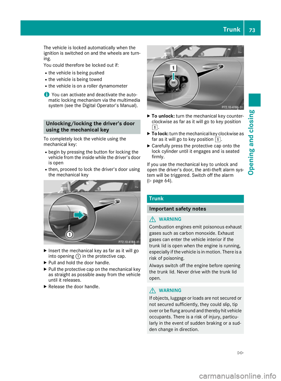
XInsert the mechanical key as far as it will go
into opening :in the protective cap.
XPull and hold the door handle.
XPull the protective cap on the mechanical key
as straight as possible away from the vehicle
until it releases.
XRelease the door handle.
XTo unlock: turn the mechanical key counter-
clockwise as far as it will go to key position
1.
XTo lock: turn the mechanical key clockwise as
far as it will go to key position 1.
XCarefully press the protective cap onto the
lock cylinder until it engages and is seated
firmly.
If you use the mechanical key to unlock and
open the driver's door, the anti-theft alarm sys-
tem will be triggered. Switch off the alarm
(
Ypage 64).
Trunk
Important safety notes
GWARNING
Combustion engines emit poisonous exhaust
gases such as carbon monoxide. Exhaust
gases can enter the vehicle interior if the
trunk lid is open when the engine is running,
especially if the vehicle is in motion. There is a
risk of poisoning.
Always switch off the engine before opening
the trunk lid. Never drive with the trunk lid
open.
GWARNING
If objects, luggage or loads are not secured or
not secured sufficiently, they could slip, tip
over or be flung around and thereby hit vehicle
occupants. There is a risk of injury, particu-
larly in the event of sudden braking or a sud-
den change in direction.
Trunk73
Opening and closing
Z
Page 128 of 294
!Use a filter when adding fuel from a fuel can.
The fuel lines and/or the fuel injection system
could otherwise be blocked by particles from
the fuel can.
If you overfill the fuel tank, fuel could spray out
when the fuel pump nozzle is removed.
For further information on fuel and fuel quality
(
Ypage 286).
Refueling
General information
Pay attention to the important safety notes
(Ypage 125).
If you unlock/lock the vehicle from the outside, the fuel filler flap also unlocks/locks.
The position of the fuel filler cap is displayed
8 in the instrument cluster. The arrow next
to the filling pump indicates the side of the vehi-
cle.
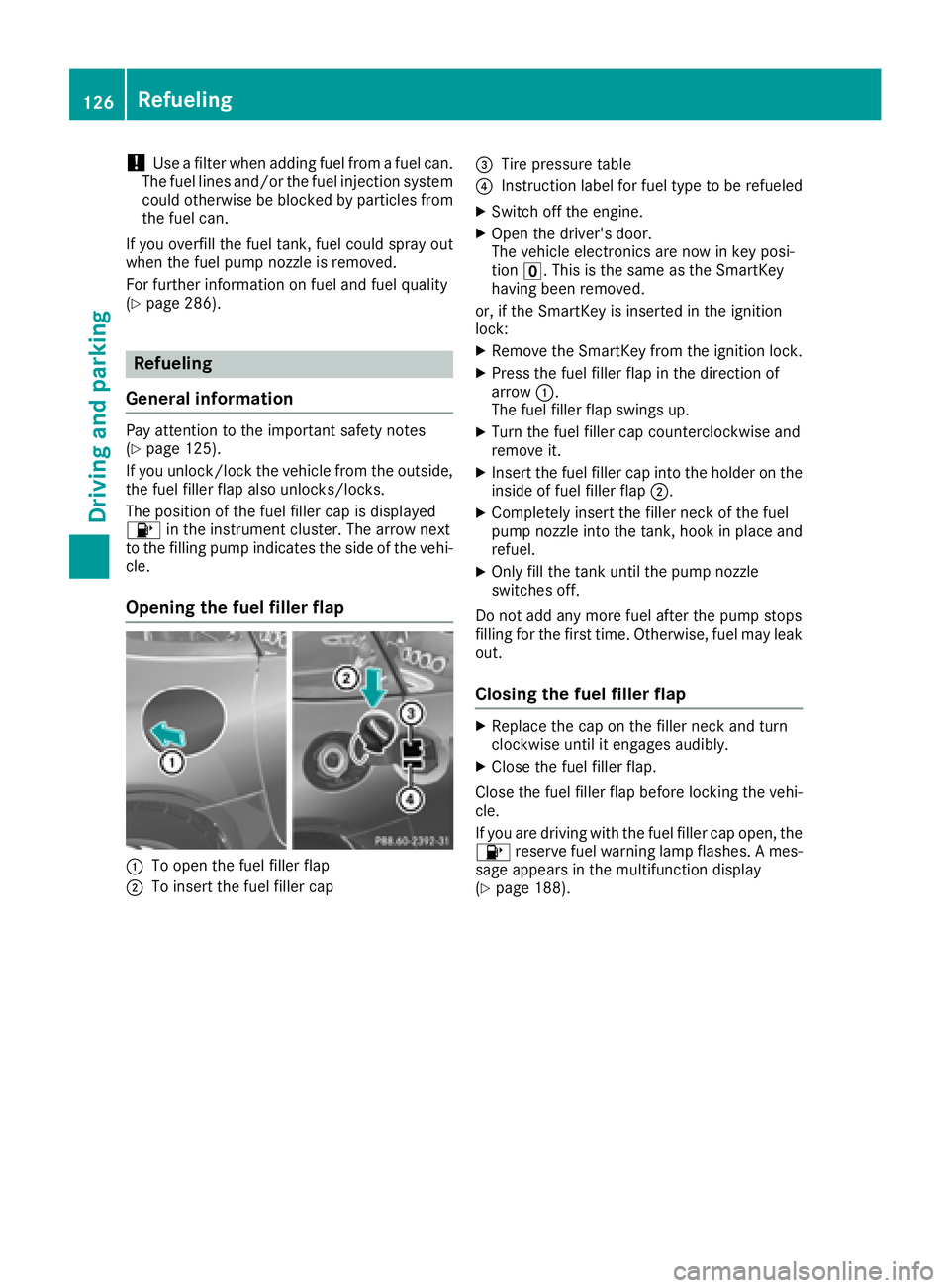
Opening the fuel filler flap
:To open the fuel filler flap
;To insert the fuel filler cap
=Tire pressure table
?Instruction label for fuel type to be refueled
XSwitch off the engine.
XOpen the driver's door.
The vehicle electronics are now in key posi-
tion u. This is the same as the SmartKey
having been removed.
or, if the SmartKey is inserted in the ignition
lock:
XRemove the SmartKey from the ignition lock.
XPress the fuel filler flap in the direction of
arrow :.
The fuel filler flap swings up.
XTurn the fuel filler cap counterclockwise and
remove it.
XInsert the fuel filler cap into the holder on the
inside of fuel filler flap ;.
XCompletely insert the filler neck of the fuel
pump nozzle into the tank, hook in place and
refuel.
XOnly fill the tank until the pump nozzle
switches off.
Do not add any more fuel after the pump stops
filling for the first time. Otherwise, fuel may leak
out.
Closing the fuel filler flap
XReplace the cap on the filler neck and turn
clockwise until it engages audibly.
XClose the fuel filler flap.
Close the fuel filler flap before locking the vehi-
cle.
If you are driving with the fuel filler cap open, the 8 reserve fuel warning lamp flashes. A mes-
sage appears in the multifunction display
(
Ypage 188).
126Refueling
Driving and parking
Page 239 of 294
Display messagesPossible causes/consequences andMSolutions
Engine Oil LevelCorrectMeasurementOnlyif Vehicl eIson Level Ground
The vehicl eis no tparked on alevel surface.
XPark th evehicl eon alevel surface.
Engine Oil LevelNot Measurabl e
Oil level measuremen twit hth eoil dipstick is possible. The measurin g
system is malfunctioning .
XVisitaqualified specialist workshop .
Adding engine oil
GWARNING
Certain component sin th eengin ecompart-
ment, suc has th eengine, radiato rand part s
of th eexhaust system, can become ver yhot .
Working in th eengin ecompartmen tposes a
ris kof injury.
Where possible, let th eengin ecool down and
touch only th ecomponent sdescribed in th e
following.
GWARNIN G
If engin eoil comes int ocontact wit hhot com-
ponents in th eengin ecompartment, it may
ignite. There is aris kof fir eand injury.
Mak esur ethat engin eoil is no tspilled next to
th efiller neck .Let th eengin ecool down and
thoroughly clean th eengin eoil off th ecom-
ponents before starting th eengine.
HEnvironmenta lnot e
Whe naddin goil, tak ecar eno tto spil lany. If
oil enters th esoil or waterways, it is harmful to
th eenvironment.
!Use only engin eoils and oil filters that are
approve dfor vehicles wit h aservic esystem. A
list of th eengin eoils and oil filters that hav e
been tested and approve din accordanc ewit h
Mercedes-Ben zSpecification sfor Service
Products is available at any authorize d
Mercedes-Ben zCenter. The followin
gcaus eengin efailure or damag e
to th eexhaust system:
RUse of engin eoils and oil filters that hav e
no tbeen expressl yapprove dfor th eservic e
system
RReplacement of engin eoil and oil filter after
th ereplacemen tinterval specified by th e
servic esystem has expired
RUse of engin eoil additive s
!Do notadd to omuc hoil. If th eoil level is
abov eth e"max "mar kon th edipstick ,to o
muc hoil has been added .This can lead to
damag eto th eengin eor th ecatalytic con-
verter. Hav eexcess oil siphoned off .
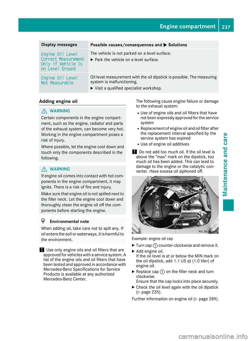
Example: engineoil cap
XTurn cap :counter-clockwise and remove it .
XAddengin eoil.
If th eoil level is at or belo wtheMIN mar kon
th eoil dipstick ,add 1. 1US qt (1. 0liter) of
engin eoil.
XReplac ecap :on th efiller neck and tur n
clockwise .
Ensur ethat th ecap locks int oplac esecurely.
XChec kth eoil level again wit hth eoil dipstick
(Ypage 235).
Further information on engin eoil (
Ypage 289).
Engine compartment237
Maintenance and care
Z
Page 240 of 294
Additional service products
Checking coolant level
GWARNIN G
Certain component sin th eengin ecompart-
ment, suc has th eengine, radiato rand part s
of th eexhaust system, can become ver yhot .
Working in th eengin ecompartmen tposes a
ris kof injury.
Wher epossible, let th eengin ecool down and
touch only th ecomponent sdescribed in th e
following.
GWARNIN G
Opening th ehoo dwhen th eengin eis over-
heated or when there is afir ein th eengin e
compartmen tcould expos eyou to hot gase s
or other servic eproducts .There is aris kof
injury.
Let an overheate dengin ecool down before
opening th ehood. If there is afir ein th e
engin ecompartment, keep th ehoo dclosed
and contact th efir edepartment.
GWARNIN G
The coolin gsystem is pressurized, particularly
when th emotor is warm .If you open th ecap ,
you could be scalded if hot coolan tsprays out .
There is aris kof injury.
Let th eengin ecool down before you open th e
cap .Wear gloves and eye protection .Slowly
open th ecap to reliev epressure.
!Befor estarting your journey, mak esur ethat
all engin ecover sare installed. Otherwise ,th e
engin ecan be damaged, e.g. throug hover-
heating .
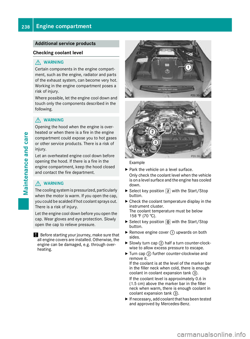
Example
XPark thevehicl eon alevel surface.
Only chec kth ecoolan tlevel when th evehicl e
is on alevel surfac eand th eengin ehas cooled
down .
XSelec tke yposition 2withth eStart/Sto p
button.
XChec kth ecoolan ttemperature display in th e
instrumen tcluster.
The coolan ttemperature mus tbe belo w
15 8 ‡ (70 †).
XSelec tke yposition uwithth eStart/Sto p
button.
XRemove engin ecover :upwards on bot h
sides.
XSlowly tur ncap ;half atur ncounter-clock -
wise to allow excess pressur eto escape.
XTurn cap ;further counter-clockwise and
remove it .
If th ecoolan tis at th elevel of th emarke rbar
in th efiller neck when cold, there is enough
coolan tin coolan texpansion tan k=.
If th ecoolan tlevel is approximately 0. 6in
(1. 5cm) abov eth emarke rbar in th efiller
neck when warm ,there is enough coolan tin
coolan texpansion tan k=.
XIf necessary, add coolan tthat has been tested
and approve dby Mercedes-Benz .
238Engine compartment
Maintenance and care
Page 241 of 294
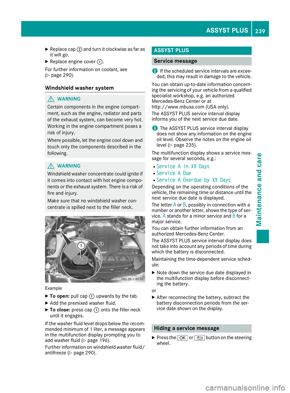
XReplacecap ;and tur nit clockwise as far as
it will go.
XReplac eengin ecover :.
Fo rfurther information on coolant, see
(
Ypage 290).
Windshield washer system
GWARNIN G
Certain component sin th eengin ecompart-
ment, suc has th eengine, radiato rand part s
of th eexhaust system, can become ver yhot .
Workin gin th eengin ecompartmen tposes a
ris kof injury.
Wher epossible, let th eengin ecool down and
touch only th ecomponent sdescribe din th e
following.
GWARNIN G
Windshield washe rconcentrate could ignit eif
it comes int ocontact wit hhot engin ecompo -
nent sor th eexhaust system. There is aris kof
fir eand injury.
Mak esur ethat no windshield washe rcon-
centrat eis spilled next to th efiller neck .
Example
XTo open :pull cap :upwards by th etab .
XAddth epremixed washe rfluid .
XTo close: press cap :onto th efiller neck
until it engages.
If th ewashe rfluid level drops belo wtherecom-
mended minimum of 1liter, amessage appear s
in th emultifunction display prompting you to
add washe rfluid (
Ypage 196).
Further information on windshield washe rfluid /
antifreez e (
Ypage 290).
ASSYST PLUS
Service message
i
If th escheduled servic eintervals are excee-
ded, this may result in damag eto th evehicle.
You can obtain up-to-date information concern -
ing th eservicing of your vehicl efrom aqualified
specialist workshop, e.g. an authorize d
Mercedes-Benz Cente ror at
http://www.mbusa.co m(US Aonly).
The ASSYS TPLU Sservic einterval display
inform syou of th enext servic edue date.
iThe ASSYS TPLU Sservic einterval display
does no tsho wany information on th eengin e
oil level. Observ eth enote son th eengin eoil
level (
Ypage 235).
The multifunction display shows aservic emes -
sage for several seconds, e.g. :
RService Ain XX Day s
RService ADue
RServic e AOverdu eby XX Day s
Dependingon th eoperating condition sof th e
vehicle, th eremaining time or distanc euntil th e
next servic edue dat eis displayed.
The lette rA
or B,possibl yin connection wit h a
number or another letter, shows th etyp eof ser -
vice. A
stand sfor aminor servic eand Bfora
major service.
You can obtain further information from an
authorize dMercedes-Benz Center.
The ASSYS TPLU Sservic einterval display does
no ttak eint oaccoun tany periods of time during
whic hth ebattery is disconnected.
Maintainin gth etime-dependen tservic esched-
ule:
XNot edown th eservic edue dat edisplayed in
th emultifunction display before disconnect -
ing th ebattery.
or
XAfte rreconnecting th ebattery, subtrac tth e
battery disconnection periods from th eser -
vic edat eshown on th edisplay.
Hiding a service message
XPress th ea or% buttonon th esteering
wheel.
ASSYST PLUS239
Maintenance and care
Z
Page 251 of 294
Rlug wrench
Ralignment bolt
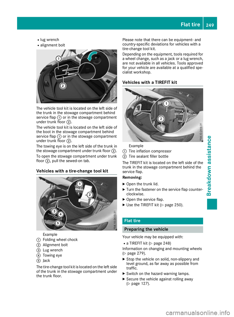
The vehicle tool kit is located on the left side of
the trunk in the stowage compartment behind
service flap:or in the stowage compartment
under trunk floor ;.
The vehicle tool kit is located on the left side of
the boot in the stowage compartment behind
service flap :or in the stowage compartment
under trunk floor ;.
The towing eye is on the left side of the trunk in
the stowage compartment under trunk floor ;.
To open the stowage compartment under trunk
floor ;, pull the sewed-on tab.
Vehicles with a tire-change tool kit
Example
:Folding wheel chock
;Alignment bolt
=Lug wrench
?Towing eye
AJack
The tire-change tool kit is located on the left side
of the trunk in the stowage compartment under
the trunk floor. Please note that there can be equipment- and
country-specific deviations for vehicles with a
tire-change tool kit.
Depending on the equipment, tools required for
a wheel change, such as a jack or a lug wrench, are not available in all vehicles. Tools approved
for your vehicle are available at a qualified spe-
cialist workshop.
Vehicles with a TIREFIT kit
Example
:Tire inflation compressor
;Tire sealant filler bottle
The TIREFIT kit is located on the left side of the
trunk in the stowage compartment behind the
service flap.
Removing:
XOpen the trunk lid.
XTurn the fastener on the service flap counter-
clockwise.
XOpen the service flap.
XUse the TIREFIT kit (Ypage 250).
Flat tire
Preparing the vehicle
Your vehicle may be equipped with:
Ra TIREFIT kit (Ypage 248)
Information on changing and mounting wheels
(
Ypage 279).
XStop the vehicle on solid, non-slippery and
level ground, as far away as possible from
traffic.
XSwitch on the hazard warning lamps.
XSecure the vehicle against rolling away
(Ypage 127).
Flat tire249
Breakdown assistance
Page 260 of 294
Also observe the following notes:
RIf the engine does not start, try jump-starting
it (Ypage 254). Tow-starting the vehicle is not
permitted.
RIf it is not possible to jump-start the vehicle,
have it transported to the nearest qualified
specialist workshop, e.g. an authorized
Mercedes-Benz Center.
If the vehicle can no longer be driven because of
an accident or breakdown, you have the follow-
ing options:
Rtransporting the vehicle
As a rule, you should have the vehicle trans-
ported.
Rtowing the vehicle with a tow rope or tow bar
Only tow the vehicle in exceptional cases. The
engine must be running if you tow the vehicle
with a tow rope or tow bar.
If the vehicle has suffered transmission damage,
have it transported on a transporter or trailer.
Observe the display messages in the instrument
cluster.
The battery must be connected and charged.
Otherwise, you:
Rwill not be able to switch on the ignition with
the Start/Stop button
Rcannot start the engine
Rcannot release the electric parking brake
Rcannot shift the automatic transmission to
position i
Disarm the automatic locking feature before the
vehicle is towed (
Ypage 72). You could other-
wise be locked out when pushing or towing the
ve
hicle.
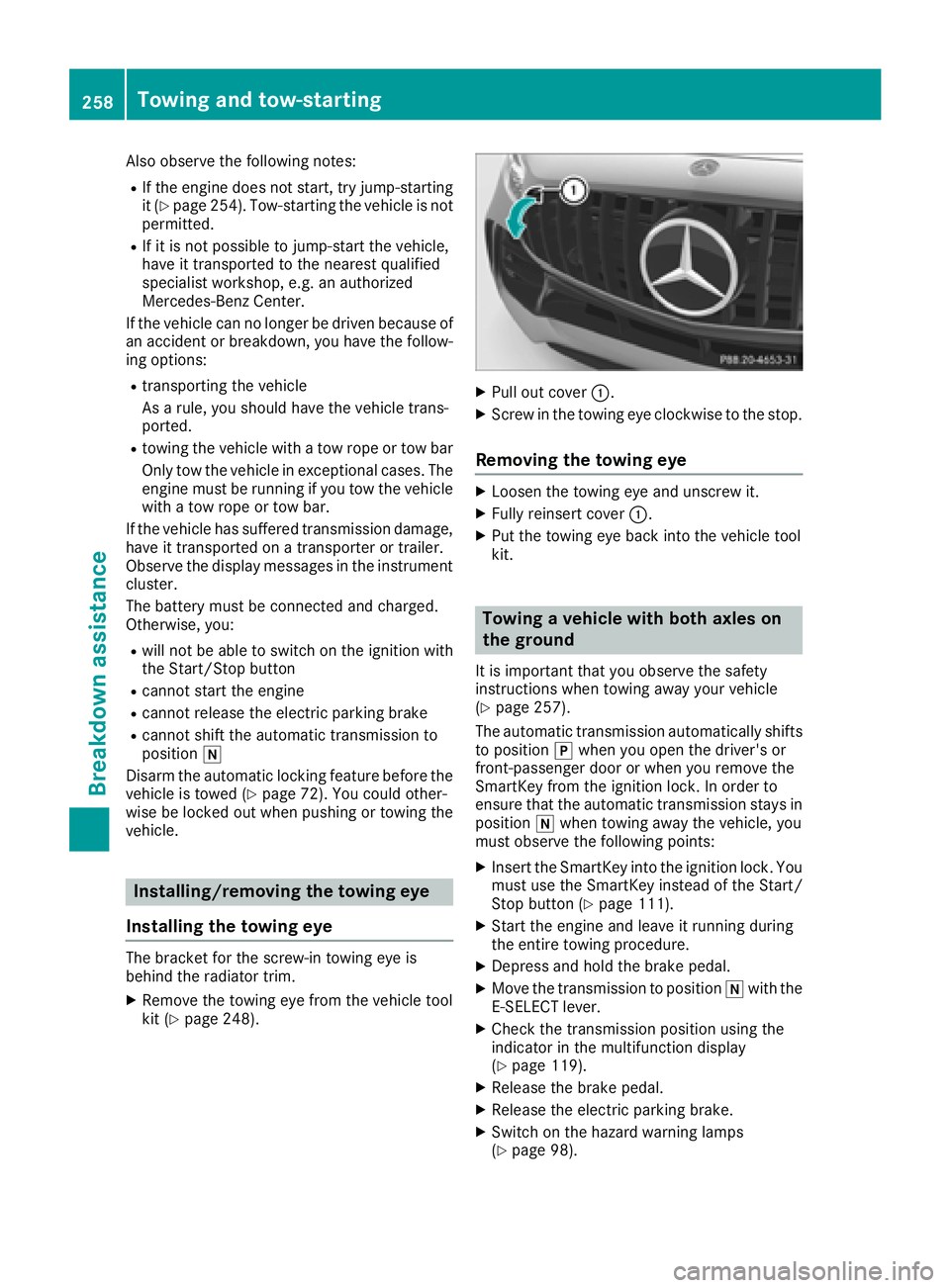
Installing/removing the towing eye
Installing the towing eye
The bracket for the screw-in towing eye is
behind the radiator trim.
XRemove the towing eye from the vehicle tool
kit (Ypage 248).
XPull out cover :.
XScrew in the towing eye clockwise to the stop.
Removing the towing eye
XLoosen the towing eye and unscrew it.
XFully reinsert cover :.
XPut the towing eye back into the vehicle tool
kit.
Towing a vehicle with both axles on
the ground
It is important that you observe the safety
instructions when towing away your vehicle
(
Ypage 257).
The automatic transmission automatically shifts
to position jwhen you open the driver's or
front-passenger door or when you remove the
SmartKey from the ignition lock. In order to
ensure that the automatic transmission stays in
position iwhen towing away the vehicle, you
must observe the following points:
XInsert the SmartKey into the ignition lock. You
must use the SmartKey instead of the Start/
Stop button (
Ypage 111).
XStart the engine and leave it running during
the entire towing procedure.
XDepress and hold the brake pedal.
XMove the transmission to position iwith the
E-SELECT lever.
XCheck the transmission position using the
indicator in the multifunction display
(
Ypage 119).
XRelease the brake pedal.
XRelease the electric parking brake.
XSwitch on the hazard warning lamps
(Ypage 98).
258Towing and tow-starting
Breakdo wn assis tance
Page 283 of 294
RBefore raising the vehicle, secure it from roll-
ing away by applying the parking brake and
inserting wheel chocks. Do not disengage the
parking brake while the vehicle is raised.
RThe jack must be placed on a firm, flat and
non-slip surface. On a loose surface, a large,
flat, load-bearing underlay must be used. On a
slippery surface, a non-slip underlay must be
used, e.g. rubber mats.
RDo not use wooden blocks or similar objects
as a jack underlay. Otherwise, the jack will not
be able to achieve its load-bearing capacity
due to the restricted height.
RMake sure that the distance between the
underside of the tires and the ground does not
exceed 1.2 in (3 cm).
RDo not place your hands or feet under the
raised vehicle.
RDo not lie under the vehicle.
RDo not start the engine when the vehicle is
raised.
RDo not open or close a door or the trunk lid
when the vehicle is raised.
RMake sure that no persons are present in the
vehicle when the vehicle is raised.
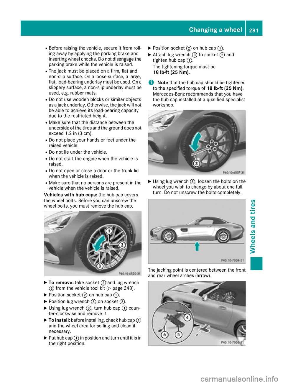
Vehicles with hub caps: the hub cap covers
the wheel bolts. Before you can unscrew the
wheel bolts, you must remove the hub cap.
XTo remove: take socket;and lug wrench
= from the vehicle tool kit (Ypage 248).
XPosition socket ;on hub cap :.
XPosition lug wrench =on socket ;.
XUsing lug wrench =, turn hub cap:coun-
ter-clockwise and remove it.
XTo install: before installing, check hub cap :
and the wheel area for soiling and clean if
necessary.
XPut hub cap :in position and turn until it is in
the right position.
XPosition socket ;on hub cap :.
XAttach lug wrench =to socket ;and
tighten hub cap :.
The tightening torque must be
18 lb-ft (25 Nm).
iNote that the hub cap should be tightened
to the specified torque of 18 lb-ft (25 Nm).
Mercedes-Benz recommends that you have
the hub cap installed at a qualified specialist
workshop.
XUsing lug wrench =, loosen the bolts on the
wheel you wish to change by about one full
turn. Do not unscrew the bolts completely.
The jacking point is centered between the front
and rear wheel arches (arrow).
Changing a wheel281
Wheels and tires
Z
Page 284 of 294
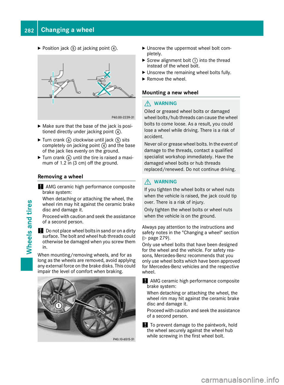
XPosition jackAat jacking point ?.
XMake sure that the base of the jack is posi-
tioned directly under jacking point ?.
XTurn crankBclockwise until jack Asits
completely on jacking point ?and the base
of the jack lies evenly on the ground.
XTurn crank Buntil the tire is raised a maxi-
mum of 1.2 in (3 cm) off the ground.
Removing a wheel
!AMG ceramic high performance composite
brake system:
When detaching or attaching the wheel, the
wheel rim may hit against the ceramic brake
disc and damage it.
Proceed with caution and seek the assistance
of a second person.
!Do not place wheel bolts in sand or on a dirty
surface. The bolt and wheel hub threads could
otherwise be damaged when you screw them in.
When mounting/removing wheels, and for as
long as the wheels are removed, avoid applying
any external force on the brake disks. This could
impair the level of comfort when braking.
XUnscrew the uppermost wheel bolt com-
pletely.
XScrew alignment bolt :into the thread
instead of the wheel bolt.
XUnscrew the remaining wheel bolts fully.
XRemove the wheel.
Mounting a new wheel
GWARNING
Oiled or greased wheel bolts or damaged
wheel bolts/hub threads can cause the wheel bolts to come loose. As a result, you could
lose a wheel while driving. There is a risk of
accident.
Never oil or grease wheel bolts. In the event of
damage to the threads, contact a qualified
specialist workshop immediately. Have the
damaged wheel bolts or hub threads
replaced/renewed. Do not continue driving.
GWARNING
If you tighten the wheel bolts or wheel nuts
when the vehicle is raised, the jack could tip
over. There is a risk of injury.
Only tighten the wheel bolts or wheel nuts
when the vehicle is on the ground.
Always pay attention to the instructions and
safety notes in the "Changing a wheel" section
(
Ypage 279).
Only use wheel bolts that have been designed
for the wheel and the vehicle. For safety rea-
sons, Mercedes-Benz recommends that you
only use wheel bolts which have been approved for Mercedes-Benz vehicles and the respective
wheel.
!AMG ceramic high performance composite
brake system:
When detaching or attaching the wheel, the
wheel rim may hit against the ceramic brake
disc and damage it.
Proceed with caution and seek the assistance
of a second person.
!To prevent damage to the paintwork, hold
the wheel securely against the wheel hub
while screwing in the first wheel bolt.
282Changing a wheel
Wheels and tires
Page 285 of 294
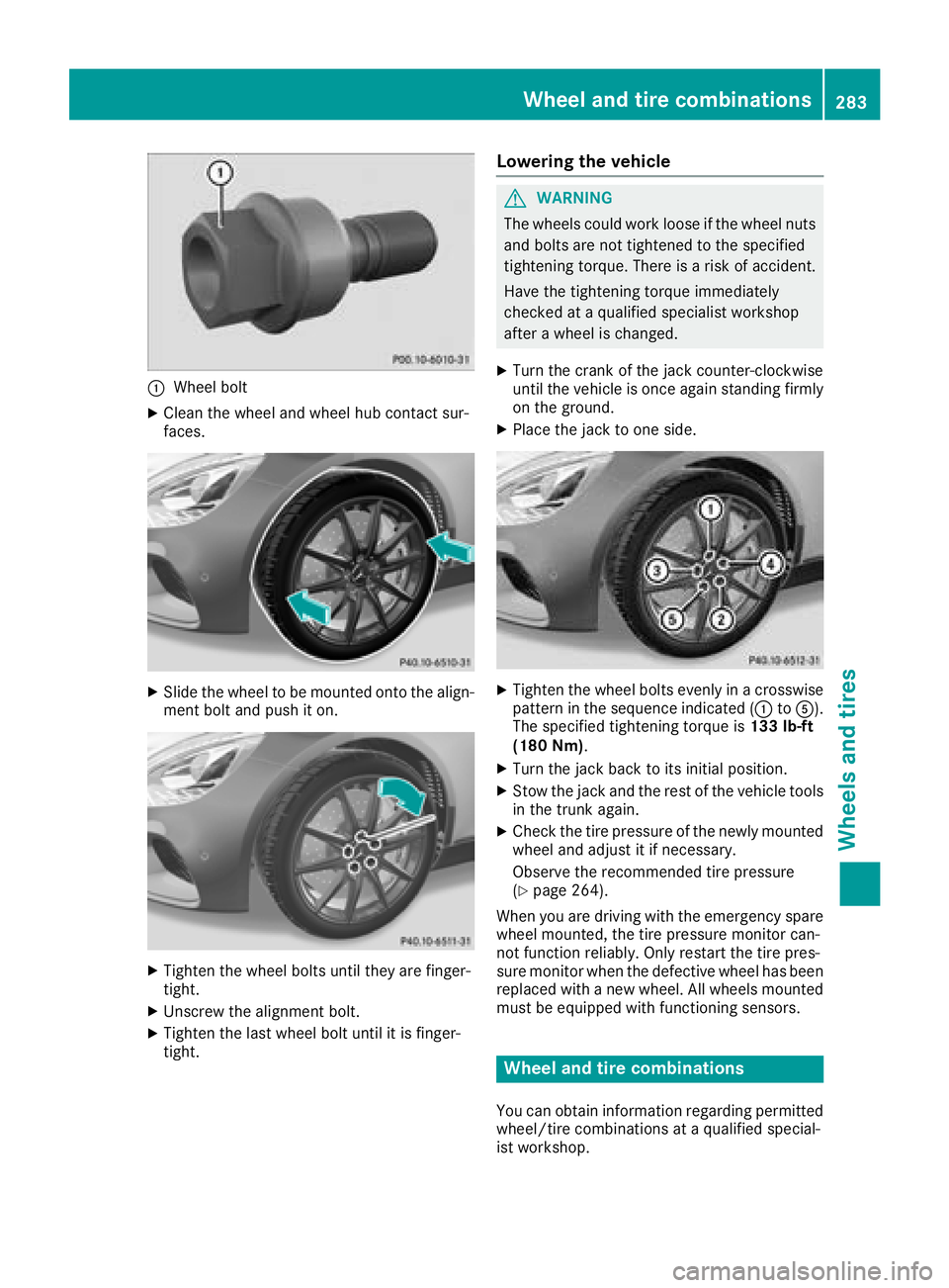
:Wheel bolt
XClean the wheel and wheel hub contact sur-
faces.
XSlide the wheel to be mounted onto the align-
ment bolt and push it on.
XTighten the wheel bolts until they are finger-
tight.
XUnscrew the alignment bolt.
XTighten the last wheel bolt until it is finger-
tight.
Lowering the vehicle
GWARNING
The wheels could work loose if the wheel nuts and bolts are not tightened to the specified
tightening torque. There is a risk of accident.
Have the tightening torque immediately
checked at a qualified specialist workshop
after a wheel is changed.
XTurn the crank of the jack counter-clockwise
until the vehicle is once again standing firmly
on the ground.
XPlace the jack to one side.
XTighten the wheel bolts evenly in a crosswisepattern in the sequence indicated (: toA).
The specified tightening torque is 133 lb-ft
(180 Nm).
XTurn the jack back to its initial position.
XStow the jack and the rest of the vehicle tools
in the trunk again.
XCheck the tire pressure of the newly mounted
wheel and adjust it if necessary.
Observe the recommended tire pressure
(
Ypage 264).
When you are driving with the emergency spare
wheel mounted, the tire pressure monitor can-
not function reliably. Only restart the tire pres-
sure monitor when the defective wheel has been replaced with a new wheel. All wheels mounted
must be equipped with functioning sensors.
Wheel and tire combinations
You can obtain information regarding permittedwheel/tire combinations at a qualified special-
ist workshop.
Wheel and tire combinations283
Wheels and tires
Z