brake MERCEDES-BENZ AMG GT ROADSTER 2018 Owners Manual
[x] Cancel search | Manufacturer: MERCEDES-BENZ, Model Year: 2018, Model line: AMG GT ROADSTER, Model: MERCEDES-BENZ AMG GT ROADSTER 2018Pages: 409, PDF Size: 7.66 MB
Page 11 of 409
U
Diagno stics connection ŌåÆ
23
V Opens the bonn et ŌåÆ
24 8
W Opens the boot lid ŌåÆ
64 X
Electric pa rking brake ŌåÆ
13 2
Y Light switch ŌåÆ
98 8
Ataglance ŌĆō Cockpit
Page 14 of 409
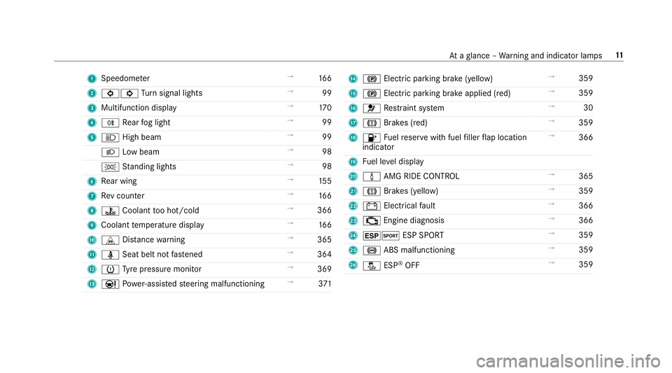
1
Speedom eter ŌåÆ
16 6
2 #! Turn signal lights ŌåÆ
99
3 Multifunction display ŌåÆ
17 0
4 R Rear fog light ŌåÆ
99
5 K High beam ŌåÆ
99
L Low beam ŌåÆ
98
T Standing lights ŌåÆ
98
6 Rear wing ŌåÆ
15 5
7 Rev counter ŌåÆ
16 6
8 ? Coolant too hot/cold ŌåÆ
366
9 Coolant temp erature display ŌåÆ
16 6
A L Distance warning ŌåÆ
365
B ├╝ Seat belt not fastened ŌåÆ
364
C h Tyre pressure monitor ŌåÆ
369
D ├É Powe r-assis tedsteering malfunctioning ŌåÆ
371 E
! Electric pa rking brake (yellow) ŌåÆ
359
F ! Electric parking brake applied (red) ŌåÆ
359
G 6 Restra int sy stem ŌåÆ
30
H J Brakes (red) ŌåÆ
359
I 8 Fuelreser vewith fuel filler flap location
indicator ŌåÆ
366
J Fuel le vel display
K ├Ā AMG RIDE CONTROL ŌåÆ
365
L J Brakes (yellow) ŌåÆ
359
M # Electrical fault ŌåÆ
366
N ; Engine diagnosis ŌåÆ
366
O ┬▒M ESP SPORT ŌåÆ
359
P ! ABS malfunctioning ŌåÆ
359
Q ├ź ESP┬«
OFF ŌåÆ
359 At
aglance ŌĆō Warning and indicator lamps 11
Page 23 of 409
Mercedes-Benz Genuine
Parts
+ ENVIRONMENTAL
NOTEEnvironmental
dama gecaused bynot using recycled
re conditioned components Daimler
AGoffers recycled reconditioned
components and pa rts with the same quality
as new parts. The same entitlement from the
implied warranty is valid as for new parts. #
Use recycled reconditioned compoŌĆÉ
nents and pa rts from Daimler AG.*
NO
TEImpairment of the operating ef fiŌĆÉ
ciency of there stra int sy stems from
ins talling accessory parts or from repairs
or we lding Airbags and seat belt
tensioners, as well as
control units and sensors forth ere stra int
sy stems, may be ins talled in thefo llowing
areas of your vehicle:
R doors
R door pillars R
door sills
R seats
R cockpit
R instrument clus ter
R centre console
R late ra lro of frame #
Do not ins tall accessory parts such as
audio sy stems in these areas. #
Do not car ryout repairs or welding. #
Have accesso ries retrofitted at a qualiŌĆÉ
fi ed specialist workshop. Yo
u could jeopardise the operating saf ety of your
ve hicle if you use parts, tyres and wheels as well
as accessories releva nt tosaf ety which ha venot
been appr ovedby Mercedes-Benz. Saf ety-re leŌĆÉ
va nt sy stems, e.g. the brake sy stem, may malŌĆÉ
function. Only use Mercedes-Benz Genuine Parts
or parts of equal qualit y.Only use tyres, wheels
and accessories that ha vebeen specifically
appr ovedfo ryo ur vehicle model. Mercedes-Benz
tests original parts and con verŌĆÉ
sion parts and accessories that ha vebeen speŌĆÉ
cifically appr ovedfo ryo ur vehicle model forth eir
re liability, saf ety and suitabilit y.Despite ongoing
ma rket resear ch, Mercedes-Benz is unable to
assess other parts. Mercedes-Benz therefore
accepts no responsibility forth e use of such
parts in Mercedes-Benz vehicles, even if they
ha ve been of ficially appr oved or independently
appr ovedby ate sting centre.
Cer tain parts are only of ficially appr ovedfor
ins tallation or modification if they comply wi th
legal requirements. All Mercedes-Benz Genuine
Pa rts meet the appr oval requ irements. The use
of non-appr oved parts may in validate theve hiŌĆÉ
cle's general operating pe rmit.
This is the case in thefo llowing situations:
R theve hicle type is dif fere nt from that for
which theve hicle's general operating pe rmit
wa s granted.
R other road users could be endangered.
R theex haust gas or noise le velge ts wo rse. 20
General no tes
Page 29 of 409
of an accident,
rescue services can use the QR
code toquickly find the appropriate rescue card
fo ryo ur vehicle. The cur rent rescue card conŌĆÉ
ta ins the most impor tant information about your
ve hicle in a compact form , e.g. thero uting of the
electric lines.
Fu rther information can be obtained at http://
www.mercedes-benz.de/qr-code. Data
storage Electronic control units
Elect
ronic control units are fitted in your vehicle.
Some of these are necessary forth e safe operaŌĆÉ
tion of your vehicle, while some assist you when
driving (driver assis tance sy stems). In addition,
yo ur vehicle pr ovides com fort and enter tainment
functions, which are also made possible byelecŌĆÉ
tronic control units.
Elect ronic control units contain da tamemories
which can temp orarily or permanently store
te ch nical information about theve hicle's operatŌĆÉ
ing state, component loads, main tenance
re qu irements and tech nical events or faults. In
general, this information documents thest ate
of a component part, a module, a sy stem or the
sur roundings such as:
R operating status of sy stem components (e.g.
fi ll le vels, battery status, tyre pressure)
R status messages concerning theve hicle or
its individual components (e.g. number of
wheel revo lutions/speed, longitudinal accelŌĆÉ
eration, lateral acceleration, display of fasŌĆÉ
te ned seat belts)
R malfunctions or faults in impor tant sy stem
components (e.g. lights, brakes)
R information on events leading tovehicle
damage
R system reactions in special driving situations
(e.g. airbag deployment, inter vention of staŌĆÉ
bility control sy stems)
R ambient conditions (e.g. temp erature, rain
sensor)
In addition toprov iding the actual control unit
function, this data assists the manufacturer in
de tecting and rectifying faults and optimising
ve hicle functions. The majority of this data is te
mp orary and is only processed in theve hicle
itself. Only a small portion of the data is stored
in theeve nt or fault memor y.
When your vehicle is serviced, tech nical da ta
from theve hicle can be read out byservice netŌĆÉ
wo rkemplo yees (e.g. workshops, manufacturŌĆÉ
ers) or third parties (e.g. breakdown services).
Services include repair services, maintenance
processes, warranty claims and quality assurŌĆÉ
ance measures, forex ample. The read out is perŌĆÉ
fo rm ed via the legally prescribed port forthe
diagnostics connection in theve hicle. The
re spective service network locations or third
parties collect, process and use the data. They
document tech nical statuses of theve hicle,
assist in finding faults and impr oving quality and
are transmitted tothe manufacturer, if necesŌĆÉ
sar y.Fu rthermore, the manufacturer is subject
to product liability. Forth is, the manufacturer
requ irestech nical da tafrom vehicles.
Fa ult memories in theve hicle can be reset by a
service outlet as part of repair or maintenance
wo rk. 26
General no tes
Page 49 of 409
#
Alw aysre place child restra int sy stems
immediately that ha vebeen damaged or
in vo lved in an accident. #
Have the securing sy stems forth ech ild
re stra int sy stems checked at a qualified
specialist workshop before ins talling a
ch ild restra int sy stem again. Av
oiding direct sunlight &
WARNING Risk of bu rns when thech ild
seat is exposed todirect sunlight
If th ech ild restra int sy stem is exposed to
direct sunlight or heat, parts could heat up.
Children could suf fer burns on these parts,
particularly on me tallic parts of thech ild
re stra int sy stem. #
Alw ays make sure that thech ild
re stra int sy stem is not exposed to
direct sunlight. #
Protect it with a blank et,fo rex ample. #
Ifth ech ild restra int sy stem has been
ex posed todirect sunlight, allow it to
cool before secu ring a child into it. #
Never lea vechildren unat tended in the
ve hicle. Obser
vewhen stopping or parking &
WARNING Risk of accident and inju ry
due tochildren left unat tended in the
ve hicle
If ch ildren are left unat tended in theve hicle,
th ey could:
R Open doo rs,th ereby endangering other
persons or road users.
R Get out and be stru ck byoncoming trafŌĆÉ
fi c.
R Ope rate ve hicle equipment and become
trapped, forex ample. In addition,
thech ildren could also set the
ve hicle in motion, forex ample by:
R Releasing the parking brake.
R Changing the transmission position.
R Starting theve hicle. #
Never lea vechildren unat tended in the
ve hicle. #
When leaving theve hicle, alw aysta ke
th eke y with you and lock theve hicle. #
Keep theve hicle key out of reach of
ch ildren. This also applies
tothe Digital Vehicle Key if the
"Digital Vehicle Key" function is activated via
Mercedes me connect. &
WARNING Risk offata l injury due to
ex posure toextreme heat or cold in the
ve hicle
If people ŌĆōparticularly children ŌĆō are exposed
to extreme temp eratures over an extended
pe riod of time, there is a risk of serious or
ev en fata l injury! 46
Occupant saf ety
Page 59 of 409
Key
Overview of
key functions &
WARNING Risk of accident and inju ry
due tochildren left unat tended in the
ve hicle
If ch ildren are left unat tended in theve hicle,
th ey could:
R open doo rs,th ereby endangering other
persons or road users.
R get out of theve hicle and be hit by
oncoming traf fic.
R ope rate ve hicle equipment and become
trapped, forex ample.
In addition, children could also set theve hiŌĆÉ
cle in motion, forex ample, by:
R releasing the parking brake.
R shifting the automatic transmission out of
park position jor shifting manual transŌĆÉ
mission into neutral.
R starting the engine. #
When leaving theve hicle, alw aysta ke
th eke y with you and lock theve hicle. #
Never lea vechildren and animals unatŌĆÉ
te nded in theve hicle. #
Keep theve hicle key out of reach of
ch ildren. *
NO
TEDama getotheke y caused by
magnetic fields #
Keep theke yaw ay from strong magŌĆÉ
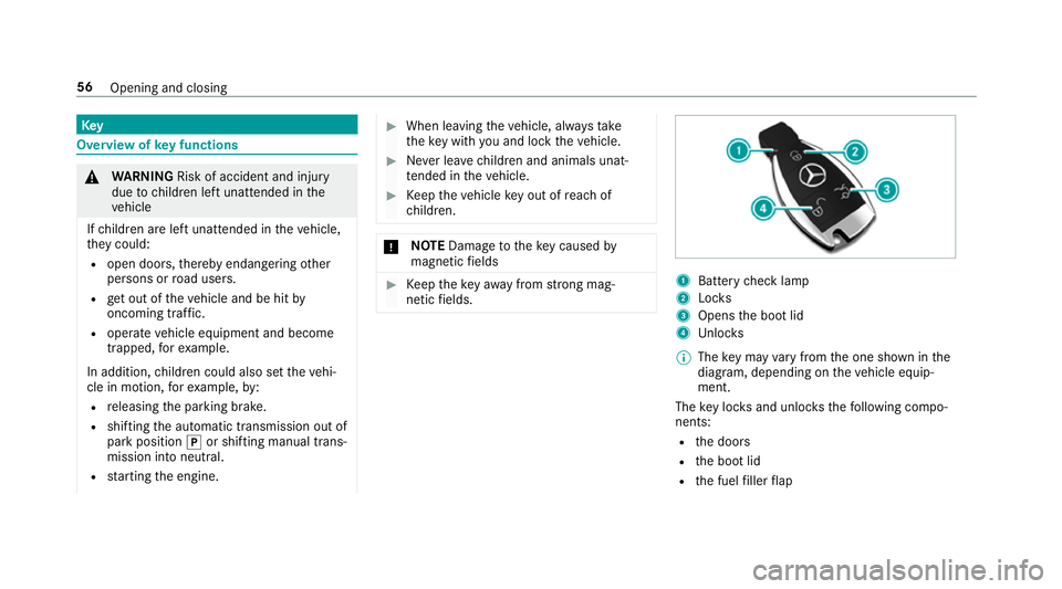
netic fields. 1
Battery check lamp
2 Locks
3 Opens the boot lid
4 Unloc ks
% The key may vary from the one shown in the
diagram, depending on theve hicle equipŌĆÉ
ment.
The key loc ksand unlo cksth efo llowing compoŌĆÉ
nents:
R the doors
R the boot lid
R the fuel filler flap 56
Opening and closing
Page 76 of 409
*
NO
TEPossible damage tothe soft top
when opening or closing The soft
top can be damaged when opening
or closing. #
Make sure there is suf ficient clearance
ab ove it. #
Ifth e soft top is dirty, wet or frozen, do
not open the soft top. #
Ifth e outside temp erature is below
-10 ┬░C, do not open the soft top. *
NO
TEDama getothe soft top caused by
heavy objects Heavy objects placed on
the soft-to p comŌĆÉ
partment co ver can dama gethe soft top or
soft-to p compartment co ver. #
Do not place he avy objects on the soft-
to p compartment co ver. #
Do not sit on the soft-to p compartment
co ver. Fo
r saf etyre asons, Mercedes-Benz recommends
opening or closing the soft top when theve hicle
is stationar y.
To open or close the soft top while you are drivŌĆÉ
ing, do not exceed a maximum speed of
50 km/h. Toavo id inter rupting the closing procŌĆÉ
ess while you are slightly exceeding this speed,
do not drive at a speed greater than 60 km/h. #
Make sure that the boot separator is closed. #
Switch on the ignition. #
Keep the brake pedal depressed when the
ve hicle is stationar y. #
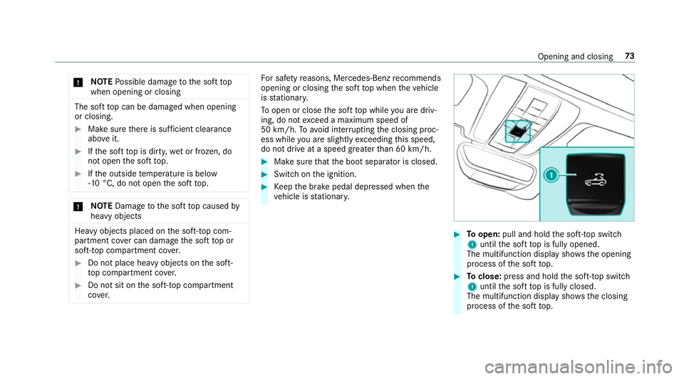
Toopen: pull and hold the soft-to p switch
1 until the soft top is fully opened.
The multifunction display sho wsthe opening
process of the soft top. #
Toclose: press and hold the soft-to p switch
1 until the soft top is fully closed.
The multifunction display sho wsthe closing
process of the soft top. Opening and closing
73
Page 79 of 409
Problem
Possible causes/consequences and M
MSolutions #
Make sure that the ignition is switched on.
The brake pedal is not depressed when theve hicle is stationar y. #
Dep ress the brake pedal.
The mechanical soft-to p components or control sy stem are defective. #
Consult a qualified specialist workshop.
The soft top has been opened and closed se veral times in a row. The soft-top drive has been switched off
au tomatical lyand will be available again af ter appro ximately ten minu tes. #
Repeat the opening or closing procedure af ter appro ximately ten minu tes.
Yo u are driving at a speed greaterth an 60 km/h. #
Reduce your speed tobelow 60 km/h. Anti-theft pr
otection Fu
nction of the immobiliser The immobiliser pr
events your vehicle from
being star ted without the cor rect key.
The immobiliser is automatically activated when
th e ignition is switched off and deactivated when
th e ignition is switched on. ATA
(Anti-Theft Alarm sy stem) Fu
nction of theATA system
If th eATA system is primed, a visual and audible
alarm is triggered in thefo llowing situations:
R when a door is opened
R when the boot lid is opened R
when the bonn etis opened
R when interior pr otection is triggered
(/ page 78)
R when tow- aw ay protection is triggered
(/ page 77) 76
Opening and closing
Page 103 of 409
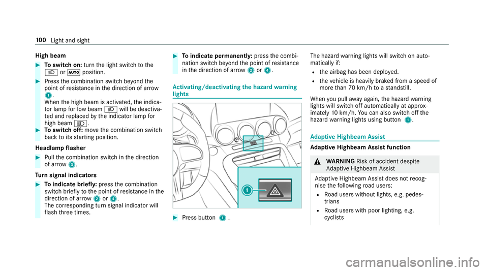
High beam
#
Toswitch on: turnthe light switch tothe
L or├ā position. #
Press the combination switch be yond the
point of resis tance in the direction of ar row
1 .
When the high beam is activated, the indicaŌĆÉ
to r lamp for low beam Lwill be deactivaŌĆÉ
te d and replaced bythe indicator lamp for
high beam K. #
Toswitch off: movethe combination switch
back toits starting position.
Headla mpflasher #
Pull the combination switch in the direction
of ar row3.
Tu rn signal indicators #
Toindicate briefl y:press the combination
switch briefly tothe point of resis tance in the
direction of ar row2or4.
The cor responding turn signal indicator will
fl ash thre e times. #
Toindicate permanentl y:press the combiŌĆÉ
nation switch be yond the point of resis tance
in the direction of ar row2or4. Ac
tivating/deactivating the hazard warning
lights #
Press button 1. The hazard
warning lights will switch on autoŌĆÉ
matically if:
R the airbag has been deplo yed.
R theve hicle is heavily braked from a speed of
more than 70 km/h toast andstill.
When you pull away again, the hazard warning
lights will switch off automatically at appr oxŌĆÉ
imately 10km/h. You can also swit choff the
hazard warning lights using button 1. Ad
aptive Highbeam Assist Ad
aptive Highbeam Assist function &
WARNING Risk of accident despi te
Ad aptive Highbeam Assist
Ad aptive Highbeam Assist does not recogŌĆÉ
nise thefo llowing road users:
R Road users without lights, e.g. pedesŌĆÉ
trians
R Road users with poor lighting, e.g.
cyclists 100
Light and sight
Page 116 of 409
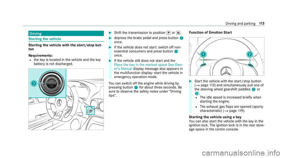
Driving
St
arting theve hicle St
arting theve hicle with thest art/s top butŌĆÉ
ton
Requ irements:
R theke y is located in theve hicle and thekey
battery is not dischar ged. #
Shift the transmission toposition jori. #
depress the brake pedal and press button 1
once. #
Ifth eve hicle does not star t:switch off non-
essential consumers and press button 1
once. #
Ifth eve hicle still does not start and the
Place the key in the marked space See Own-
er's Manual display message also appears in
th e multifunction display: start theve hicle in
emer gency operation mode.
Yo u can swit choff the engine while driving by
pressing button 1for about thre e seconds. Be
sure toobser vethe saf ety no tes under "Driving
tips". Fu
nction of Emotion Start #
Start theve hicle with thest art/ stop button
(/ page 113) and simultaneous ly pull one of
th esteering wheel gearshift paddles 1or
2.
R The idle speed is inc reased brief ly when
st arting the engine.
R The exhaust gasflaps are opened (spo rty
ch aracteristic) (/ page119).
St arting theve hicle using a key
Yo u can also start theve hicle with theke y in the
ignition loc k.The ignition lock is in there ar stowŌĆÉ
age space in the cent reconsole. Driving and pa
rking 11 3