lights MERCEDES-BENZ AMG GT ROADSTER 2018 Owners Manual
[x] Cancel search | Manufacturer: MERCEDES-BENZ, Model Year: 2018, Model line: AMG GT ROADSTER, Model: MERCEDES-BENZ AMG GT ROADSTER 2018Pages: 409, PDF Size: 7.66 MB
Page 10 of 409
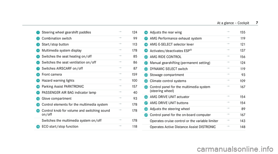
1
Steering wheel gearshift paddles →
124
2 Combination swit ch →
99
3 Start/ stop button →
11 3
4 Multimedia sy stem display →
178
5 Switches the seat heating on/off →
85
6 Switches the seat ventilation on/o ff →
86
7 Switches AIRSCARF on/off →
87
8 Front camera →
15 9
9 Haza rdwa rning lights →
100
A Parking Assist PARKTRONIC →
157
B PASSENGER AIR BAG indicator lamp →
40
C Glovecompa rtment →
93
D Control elements forth e multimedia sy stem →
178
E Control knob forvo lume and switching sound
on/off →
178
Switches the multimedia sy stem on/off →
178
F ECO start/ stop function →
11 8 G
Adjusts there ar wing →
15 5
H AMG Performance exhaust sy stem →
11 9
I AMG E-SELECT selector le ver→
121
J Activates/deacti vates ESP ®
→
137
K AMG RIDE CONTROL →
15 6
L Manual gearshifting (permanent setting) →
124
M DYNA MIC SELECT switch →
11 9
N Stow age compartment →
93
O Climate control sy stems →
109
P Control panel forth e multimedia sy stem
(s te ering wheel) →
167
Q AMG DRIVE UNIT actuator →
154
R AMG DRIVE UNIT buttons →
154
S Adjusts thesteering wheel →
89
T Control panel forth e on-board computer →
167
Operates cruise contro l ortheva riable limiter →
14 3
Operates Active Dis tance Assi stDISTRONIC →
14 8 At
aglance – Cockpit 7
Page 14 of 409
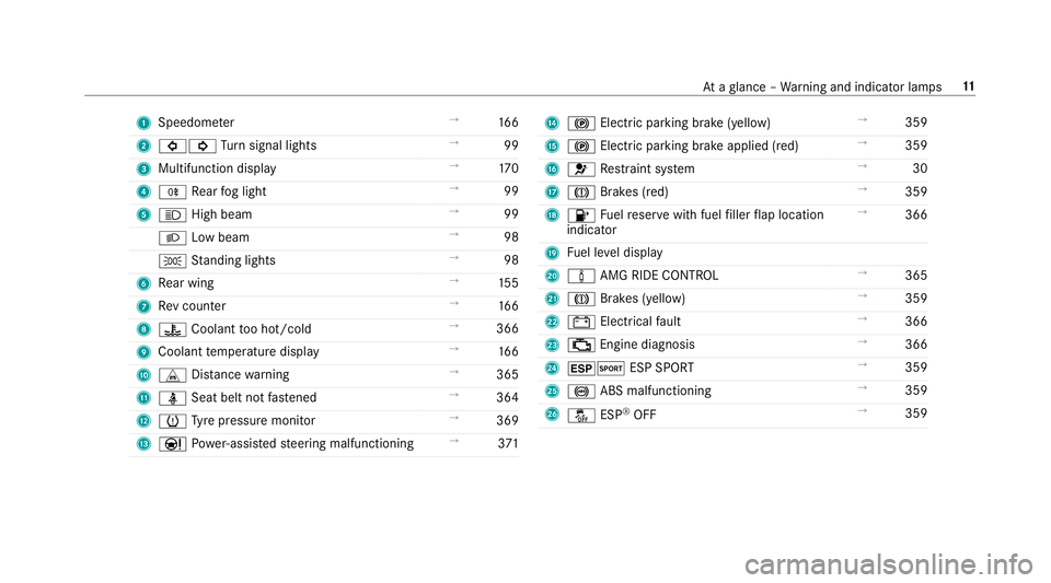
1
Speedom eter →
16 6
2 #! Turn signal lights →
99
3 Multifunction display →
17 0
4 R Rear fog light →
99
5 K High beam →
99
L Low beam →
98
T Standing lights →
98
6 Rear wing →
15 5
7 Rev counter →
16 6
8 ? Coolant too hot/cold →
366
9 Coolant temp erature display →
16 6
A L Distance warning →
365
B ü Seat belt not fastened →
364
C h Tyre pressure monitor →
369
D Ð Powe r-assis tedsteering malfunctioning →
371 E
! Electric pa rking brake (yellow) →
359
F ! Electric parking brake applied (red) →
359
G 6 Restra int sy stem →
30
H J Brakes (red) →
359
I 8 Fuelreser vewith fuel filler flap location
indicator →
366
J Fuel le vel display
K à AMG RIDE CONTROL →
365
L J Brakes (yellow) →
359
M # Electrical fault →
366
N ; Engine diagnosis →
366
O ±M ESP SPORT →
359
P ! ABS malfunctioning →
359
Q å ESP®
OFF →
359 At
aglance – Warning and indicator lamps 11
Page 20 of 409
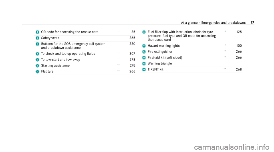
1
QR code for accessing there scue card →
25
2 Safetyve sts →
265
3 Buttons forth e SOS emer gency call sy stem
and breakdown assis tance →
220
4 Tocheck and top up operating fluids →
307
5 Totow- start and tow aw ay →
278
6 Starting assis tance →
276
7 Flat tyre →
266 8
Fuelfiller flap with instruction labels for tyre
pressu re, fuel type and QR code for accessing
th ere scue card →
12 5
9 Haza rdwa rning lights →
100
A Fire extinguisher →
266
B First-aid kit (so ftsided) →
266
C Warning triangle
D TIREFIT kit →
268 At
aglance – Emer gencies and breakdowns 17
Page 29 of 409
of an accident,
rescue services can use the QR
code toquickly find the appropriate rescue card
fo ryo ur vehicle. The cur rent rescue card con‐
ta ins the most impor tant information about your
ve hicle in a compact form , e.g. thero uting of the
electric lines.
Fu rther information can be obtained at http://
www.mercedes-benz.de/qr-code. Data
storage Electronic control units
Elect
ronic control units are fitted in your vehicle.
Some of these are necessary forth e safe opera‐
tion of your vehicle, while some assist you when
driving (driver assis tance sy stems). In addition,
yo ur vehicle pr ovides com fort and enter tainment
functions, which are also made possible byelec‐
tronic control units.
Elect ronic control units contain da tamemories
which can temp orarily or permanently store
te ch nical information about theve hicle's operat‐
ing state, component loads, main tenance
re qu irements and tech nical events or faults. In
general, this information documents thest ate
of a component part, a module, a sy stem or the
sur roundings such as:
R operating status of sy stem components (e.g.
fi ll le vels, battery status, tyre pressure)
R status messages concerning theve hicle or
its individual components (e.g. number of
wheel revo lutions/speed, longitudinal accel‐
eration, lateral acceleration, display of fas‐
te ned seat belts)
R malfunctions or faults in impor tant sy stem
components (e.g. lights, brakes)
R information on events leading tovehicle
damage
R system reactions in special driving situations
(e.g. airbag deployment, inter vention of sta‐
bility control sy stems)
R ambient conditions (e.g. temp erature, rain
sensor)
In addition toprov iding the actual control unit
function, this data assists the manufacturer in
de tecting and rectifying faults and optimising
ve hicle functions. The majority of this data is te
mp orary and is only processed in theve hicle
itself. Only a small portion of the data is stored
in theeve nt or fault memor y.
When your vehicle is serviced, tech nical da ta
from theve hicle can be read out byservice net‐
wo rkemplo yees (e.g. workshops, manufactur‐
ers) or third parties (e.g. breakdown services).
Services include repair services, maintenance
processes, warranty claims and quality assur‐
ance measures, forex ample. The read out is per‐
fo rm ed via the legally prescribed port forthe
diagnostics connection in theve hicle. The
re spective service network locations or third
parties collect, process and use the data. They
document tech nical statuses of theve hicle,
assist in finding faults and impr oving quality and
are transmitted tothe manufacturer, if neces‐
sar y.Fu rthermore, the manufacturer is subject
to product liability. Forth is, the manufacturer
requ irestech nical da tafrom vehicles.
Fa ult memories in theve hicle can be reset by a
service outlet as part of repair or maintenance
wo rk. 26
General no tes
Page 33 of 409
Re
stra int sy stem functionality When
the ignition is switched on, a self-test is
per form ed, during which the6 restra int sys‐
te m wa rning lamp lights up. It goes out no later
th an a few seconds af terth eve hicle is star ted.
The components of there stra int sy stem are then
functional. Malfunctioning
restra int sy stem A malfunction has occur
red in there stra int sys‐
te m if:
R the6 restra int sy stem warning lamp does
not light up when the ignition is switched on
R the6 restra int sy stem warning lamp
lights up continuously or repeatedly during a
journey &
WARNING Risk of inju rydue tomalfunc‐
tions in there stra int sy stem
If th ere stra int sy stem is malfunctioning,
re stra int sy stem components may be trig‐
ge red unintentionally or may not deploy as intended during an accident. This may af
fect
th e seat belt tensioner or airbag, forex am‐
ple. #
Have there stra int sy stem checked and
re paired immediately at a qualified spe‐
cialist workshop. Fu
nction of there stra int sy stem in an acci‐
dent How
there stra int sy stem works is de term ined by
th e se verity of the impact de tected and the type
of accident anticipated:
R Frontal impact
R Rear impact
R Side impact
R Rollover
The activation thre sholds forth e components of
th ere stra int sy stem are de term ined based on
th eev aluation of the sensor values measured at
va rious points in theve hicle. This process is pre-
em ptive in nature. The triggering/deployment of
th e components of there stra int sy stem must ta
ke place in good time at thest art of the colli‐
sion.
Fa ctors whi chcan only be seen and measu red
af te r a collision has occur red do not play a deci‐
sive role in the deployment of an airbag. Nordo
th ey prov ide an indication of airbag deployment.
The vehicle may be deformed significantly with‐
out an airbag being deplo yed. This is the case if
only parts which are relatively easily deformed
are af fected and thera te ofvehicle deceleration
is not high. Con versely, an airbag may be
deplo yedev en though theve hicle suf fers only
minor deformation. If very rigid vehicle parts
such as longitudinal members are hit, forex am‐
ple, this may result in suf ficiently high le vels of
ve hicle deceleration. 30
Occupant saf ety
Page 43 of 409
R
The front passenger seat has been mo ved
as far back as possible.
R The person is seated cor rectl y. #
Ensu re, bo thbefore and during the jour‐
ne y,that thest atus of the front
passenger airbag is cor rect. If
th e front passenger seat is occupied, the clas‐
sification of the person or child restra int sy stem
on the front passenger seat take s place af terthe
front passenger front airbag shutoff self-test.
The PASSENGER AIR BAG indicator lamps dis‐
play thest atus of the front passenger front air‐
bag.
Alw ays obser vethe no tes on the function of the
PA SSENGER AIR BAG indicator lamps
(/ page 40). Fu
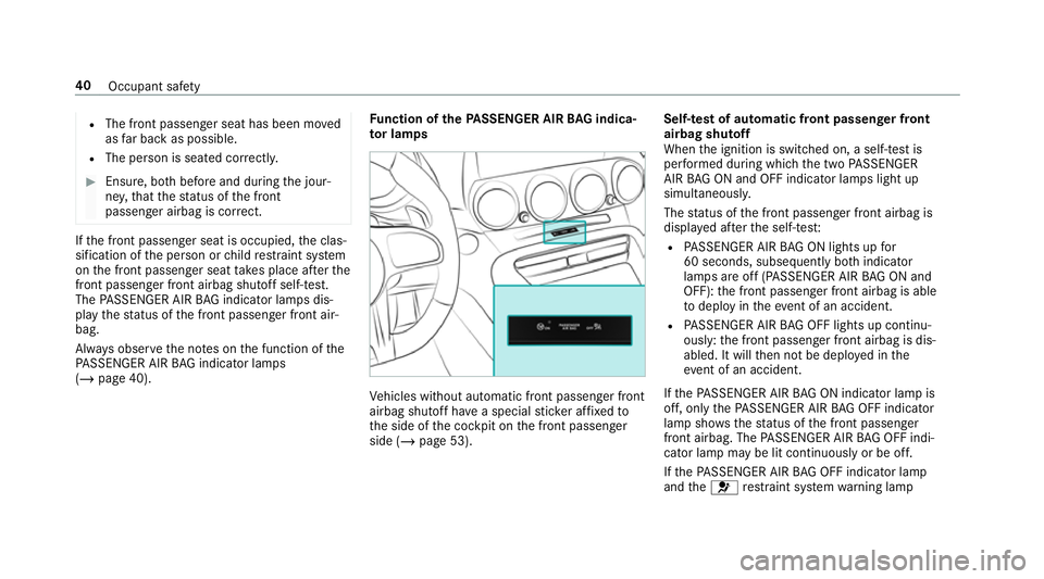
nction of thePA SSENGER AIR BAG indica‐
to r lamps Ve
hicles without automatic front passenger front
airbag shutoff ha vea special sticke r af fixe dto
th e side of the cockpit on the front passenger
side (/ page 53). Self-test of automatic front passenger front
airbag shutoff
When
the ignition is switched on, a self-test is
per form ed during which the two PASSENGER
AIR BAG ON and OFF indicator lamps light up
simul taneously.
The status of the front passenger front airbag is
displa yed af terth e self-tes t:
R PASSENGER AIR BAG ON lights up for
60 seconds, subsequently bo thindicator
lamps are off (PASSENGER AIR BAG ON and
OFF): the front passenger front airbag is able
to deploy in theeve nt of an accident.
R PASSENGER AIR BAG OFF lights up continu‐
ously: the front passenger front airbag is dis‐
abled. It will then not be deplo yed in the
eve nt of an accident.
If th ePA SSENGER AIR BAG ON indicator lamp is
off, on lythePA SSENGER AIR BAG OFF indicator
lamp sho ws thest atus of the front passenger
front airbag. The PASSENGER AIR BAG OFF indi‐
cator lamp may be lit continuously or be off.
If th ePA SSENGER AIR BAG OFF indicator lamp
and the6 restra int sy stem warning lamp 40
Occupant saf ety
Page 45 of 409
wa
rds and down wards from the seat
belt guide. #
Alw ays obser vethech ild restra int sys‐
te m manufacturer's ins tallation instruc‐
tions. When
fitting a child restra int sy stem tothe front
passenger seat, obser vetheve hicle-specific
information (/ page 53).
If a person is sitting on the front passenger
seat: PASSENGER AIR BAG OFF may be lit con‐
tinuously or be off, depending on the person's
st ature.
A person on the front passenger seat must
alw ays obser vethefo llowing information:
R Ifth e front passenger seat is occupied byan
adult or a person with a stature cor respond‐
ing tothat of an adult, thePA SSENGER AIR
BA G OFF indicator lamp must be off. This
indicates that the front passenger front air‐
bag is enabled.
If th ePA SSENGER AIR BAG OFF indicator
lamp is lit continuousl y,an adult or person with a build cor
responding tothat of an adult
should not use the front passenger seat.
R Ifth e front passenger seat is occupied by a
person of smaller stature (e.g. a teenager or
small adult), thePA SSENGER AIR BAG OFF
indicator lamp either lights up continuously
or remains off, depending on there sult of the
classi fication.
- Ifth ePA SSENGER AIR BAG OFF indicator
lamp is off: mo vethe front passenger
seat as far back as possible.
- Ifth ePA SSENGER AIR BAG OFF indicator
lamp is lit continuously: the person of
smaller stature should not use the front
passenger seat. &
WARNING Risk of inju ryor death when
th ePA SSENGER AIR BAG OFF indicator
lamp is lit
If th ePA SSENGER AIR BAG OFF indicator
lamp remains lit af terth e sy stem self-test,
th e front passenger airbag is disabled. It will
not be deplo yed in theeve nt of an accident.
In this case, the front passenger airbag can‐ not per
form its intended pr otective function,
e.g. when a person is seated in the front
passenger seat.
That person could, forex ample, come into
contact with theve hicle interior, especially if
th e person is sitting too close tothe cockpit.
If th e front passenger seat is occupied,
alw ays ensure that:
R The classification of the person in the
front passenger seat is cor rect and the
front passenger airbag is enabled or disa‐
bled in accordance with the person in the
front passenger seat.
R The person is sea ted properly with a cor‐
re ctly fastened seat belt.
R The front passenger seat has been mo ved
as far back as possible. Be sure
toalso obse rveth efo llowing fur ther
re lated subjects:
R Child restra int sy stem on the front passenger
seat (/ page 53). 42
Occupant saf ety
Page 61 of 409
#
Todeactivate: pressthe& button on the
ke y twice in quick succession.
The battery check lamp of theke yflashes
twice brief lyand lights up once. #
Toactivate: press any button on thekey.
% When theve hicle is star ted with theke y in
th estow age compartment of the cent recon‐
sole, theke y functions are automatical ly
activated (/ page113). Re
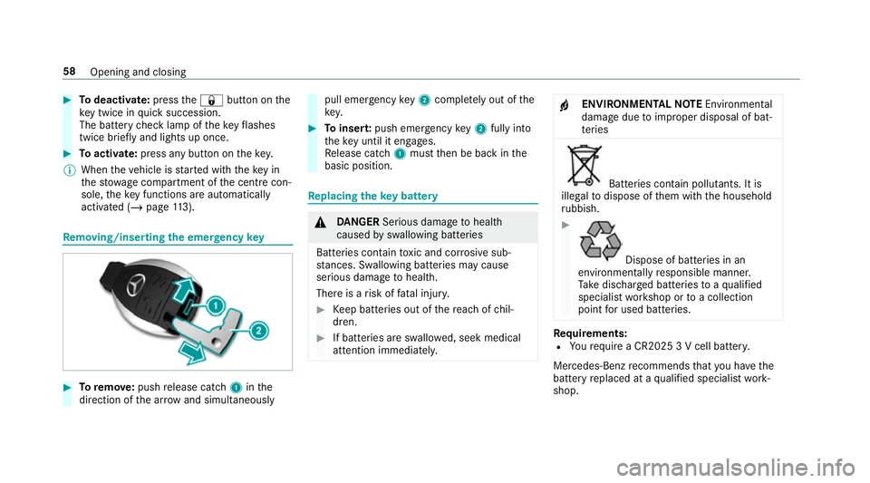
moving/inserting the eme rgency key #
Toremo ve:push release cat ch1 inthe
direction of the ar row and simul taneously pull eme
rgency key2 comp lete ly out of the
key. #
Toinser t:push emer gency key2 fully in to
th eke y until it en gage s.
Re lease cat ch1 must then be back in the
basic position. Re
placing the key battery &
DANG ER Serious damage tohealth
caused byswallowing batteries
Batteries contain toxic and cor rosive sub‐
st ances. Swallowing bat teries may cause
serious damage tohealth.
There is a risk of fata l injur y. #
Keep batteries out of there ach of chil‐
dren. #
If batteries are swallo wed, seek medical
attention immediately. +
ENVIRONMEN
TALNO TEEnvironmental
dama gedue toimproper disposal of bat‐
te ries Batteries conta
in pollutants. It is
illegal todispose of them with the household
ru bbish. #
Dispose of batteries in an
environmen tally responsible manner.
Ta ke dischar ged batteries toaqu alified
specialist workshop or toa collection
point for used batteries. Re
quirements:
R Yourequ ire a CR2025 3 V cell batter y.
Mercedes-Benz recommends that you ha vethe
battery replaced at a qualified specialist work‐
shop. 58
Opening and closing
Page 101 of 409
Exterior lighting
Note
s onchanging the lights when driving
abroad It is not necessary
tochange the headlamps.
The legal requirements are also met in countries
in which traf fic drives on theot her side of the
ro ad. Information about lighting sy
stems and your
re sponsibility The
various lighting sy stems of theve hicle are
only aids. The driver of theve hicle is responsible
fo r cor rect vehicle illumination in accordance
with the pr evailing light and visibility conditions,
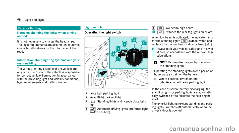
legal requirements and traf fic situation. Light switch
Ope
rating the light switch 1
W Left pa rking light
2 X Right parking light
3 T Standing lights and licence plate light‐
ing
4 Ã Automatic driving lights (prefer red light
switch position) 5
L Low beam/high beam
6 R Switches there ar fog lights on or off
When low beam is activated, the indicator lamp
fo rth est anding lights Tis deactivated and
re placed bythe low beam indicator lamp L. #
Alw ays park your vehicle safely and in a well-
lit area, in accordance with there leva nt le gal
st ipulations.
* NO
TEBattery discharging byoperating
th est anding lights Operating
thest anding lights over a period of
hours puts a stra in on the batter y. #
Where possible, switch on the
ri ght X or left Wparking light. In
the case of se vere battery discharging, the
st anding lights or parking lights are automati‐
cally swit ched off tofacilitate the next engine
st art.
The exterior lighting (e xcept standing and park‐
ing lights) swit ches off automatically when the
driver's door is opened. 98
Light and sight
Page 102 of 409
R
Obser vethe no tes on sur round lighting
(/ page 102).
Au tomatic driving lights function
The standing lights, low beam and daytime run‐
ning lights are switched on au tomatical ly
depending on the ignition status and the light
conditions. &
WARNING Risk of accident when the
dipped beam is switched off in poor visi‐
bility
When the light switch is set toà ,the
dipped beam may not be switched on auto‐
matically if there is fog, snow or other causes
of poor visibility such as spr ay.#
In such cases, turn the light switch to
L . The automatic driving lights are only an aid.
Yo u
are responsible forve hicle lighting. Switching
there ar fog lights on or off
Re quirements:
R The light switch is in theL orà posi‐
tion. #
Press the R button.
Please obser vethe count ry-specific la wsonthe
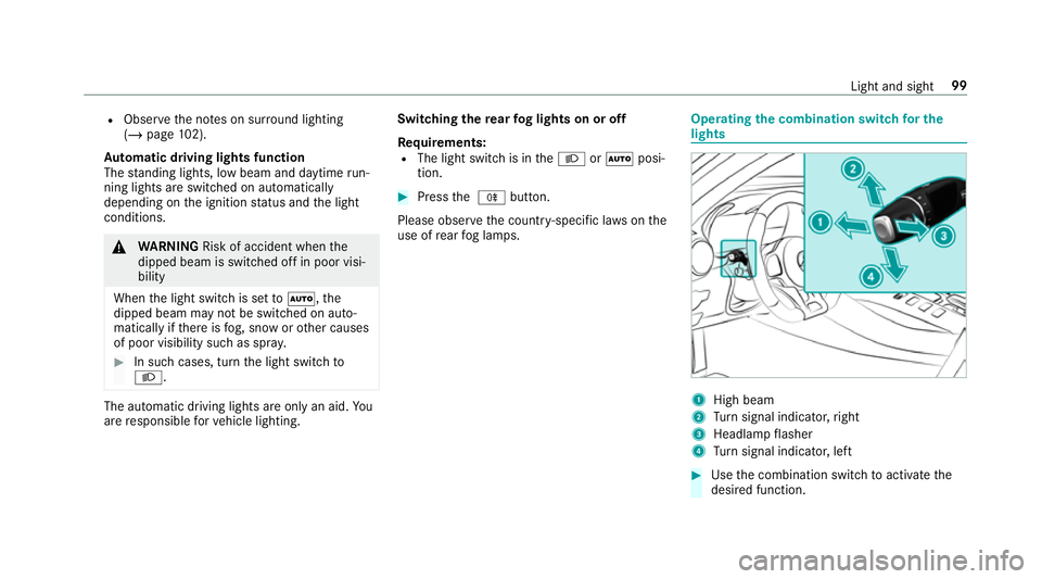
use of rear fog lamps. Operating
the combination switch for the
lights 1
High beam
2 Turn signal indicator, right
3 Headlamp flasher
4 Turn signal indicator, left #
Use the combination switch toactivate the
desired function. Light and sight
99