turn signal MERCEDES-BENZ AMG GT ROADSTER 2018 Owners Manual
[x] Cancel search | Manufacturer: MERCEDES-BENZ, Model Year: 2018, Model line: AMG GT ROADSTER, Model: MERCEDES-BENZ AMG GT ROADSTER 2018Pages: 409, PDF Size: 7.66 MB
Page 14 of 409
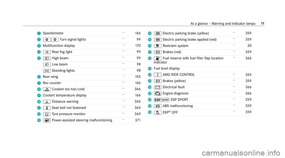
1
Speedom eter →
16 6
2 #! Turn signal lights →
99
3 Multifunction display →
17 0
4 R Rear fog light →
99
5 K High beam →
99
L Low beam →
98
T Standing lights →
98
6 Rear wing →
15 5
7 Rev counter →
16 6
8 ? Coolant too hot/cold →
366
9 Coolant temp erature display →
16 6
A L Distance warning →
365
B ü Seat belt not fastened →
364
C h Tyre pressure monitor →
369
D Ð Powe r-assis tedsteering malfunctioning →
371 E
! Electric pa rking brake (yellow) →
359
F ! Electric parking brake applied (red) →
359
G 6 Restra int sy stem →
30
H J Brakes (red) →
359
I 8 Fuelreser vewith fuel filler flap location
indicator →
366
J Fuel le vel display
K à AMG RIDE CONTROL →
365
L J Brakes (yellow) →
359
M # Electrical fault →
366
N ; Engine diagnosis →
366
O ±M ESP SPORT →
359
P ! ABS malfunctioning →
359
Q å ESP®
OFF →
359 At
aglance – Warning and indicator lamps 11
Page 66 of 409
Problem
Possible causes/consequences and M
MSolutions
R The key is faulty. #
Activate theke y functions (/ page57). #
Check the battery using the battery check lamp and replace if necessary (/ page 58). #
Use the emer gency keyto unlo ckor lock theve hicle (/ page 58). #
Have theve hicle and keych ecked at a qualified specialist workshop. Ac
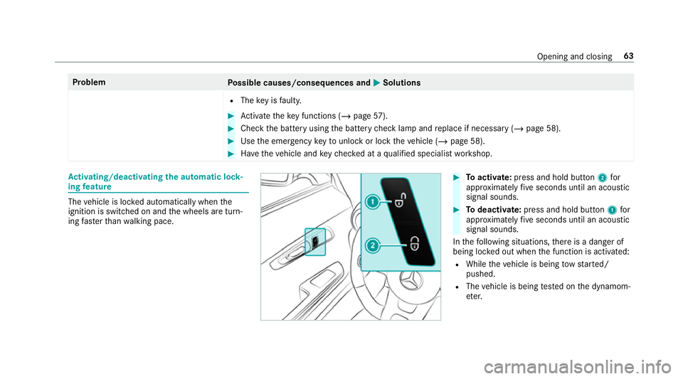
tivating/deactivating the automatic lo ck‐
ing feature The
vehicle is loc ked automatically when the
ignition is switched on and the wheels are turn‐
ing fast erthan walking pace. #
Toactivate: press and hold button 2for
appr oximately five seconds until an acoustic
signal sounds. #
Todeactivate: press and hold button 1for
appr oximately five seconds until an acoustic
signal sounds.
In thefo llowing situations, there is a danger of
being loc ked out when the function is activated:
R While theve hicle is being tow star ted/
pushed.
R The vehicle is being tested on the dynamom‐
et er. Opening and closing
63
Page 102 of 409
R
Obser vethe no tes on sur round lighting
(/ page 102).
Au tomatic driving lights function
The standing lights, low beam and daytime run‐
ning lights are switched on au tomatical ly
depending on the ignition status and the light
conditions. &
WARNING Risk of accident when the
dipped beam is switched off in poor visi‐
bility
When the light switch is set toà ,the
dipped beam may not be switched on auto‐
matically if there is fog, snow or other causes
of poor visibility such as spr ay.#
In such cases, turn the light switch to
L . The automatic driving lights are only an aid.
Yo u
are responsible forve hicle lighting. Switching
there ar fog lights on or off
Re quirements:
R The light switch is in theL orà posi‐
tion. #
Press the R button.
Please obser vethe count ry-specific la wsonthe
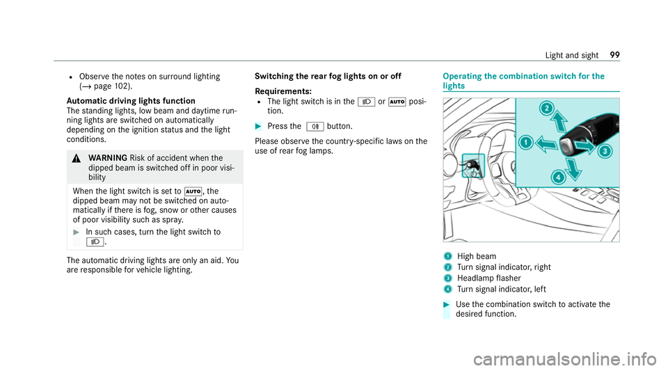
use of rear fog lamps. Operating
the combination switch for the
lights 1
High beam
2 Turn signal indicator, right
3 Headlamp flasher
4 Turn signal indicator, left #
Use the combination switch toactivate the
desired function. Light and sight
99
Page 103 of 409
High beam
#
Toswitch on: turnthe light switch tothe
L orà position. #
Press the combination switch be yond the
point of resis tance in the direction of ar row
1 .
When the high beam is activated, the indica‐
to r lamp for low beam Lwill be deactiva‐
te d and replaced bythe indicator lamp for
high beam K. #
Toswitch off: movethe combination switch
back toits starting position.
Headla mpflasher #
Pull the combination switch in the direction
of ar row3.
Tu rn signal indicators #
Toindicate briefl y:press the combination
switch briefly tothe point of resis tance in the
direction of ar row2or4.
The cor responding turn signal indicator will
fl ash thre e times. #
Toindicate permanentl y:press the combi‐
nation switch be yond the point of resis tance
in the direction of ar row2or4. Ac
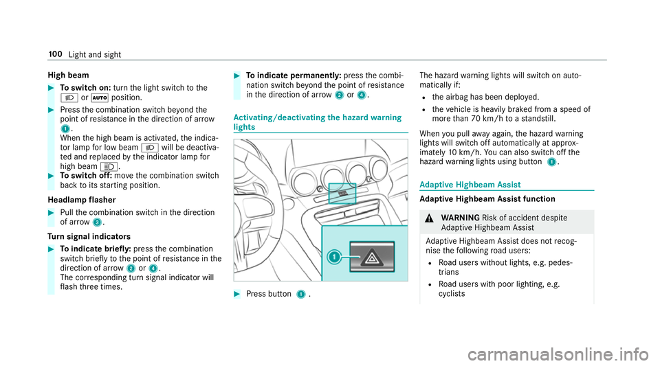
tivating/deactivating the hazard warning
lights #
Press button 1. The hazard
warning lights will switch on auto‐
matically if:
R the airbag has been deplo yed.
R theve hicle is heavily braked from a speed of
more than 70 km/h toast andstill.
When you pull away again, the hazard warning
lights will switch off automatically at appr ox‐
imately 10km/h. You can also swit choff the
hazard warning lights using button 1. Ad
aptive Highbeam Assist Ad
aptive Highbeam Assist function &
WARNING Risk of accident despi te
Ad aptive Highbeam Assist
Ad aptive Highbeam Assist does not recog‐
nise thefo llowing road users:
R Road users without lights, e.g. pedes‐
trians
R Road users with poor lighting, e.g.
cyclists 100
Light and sight
Page 150 of 409
Ac
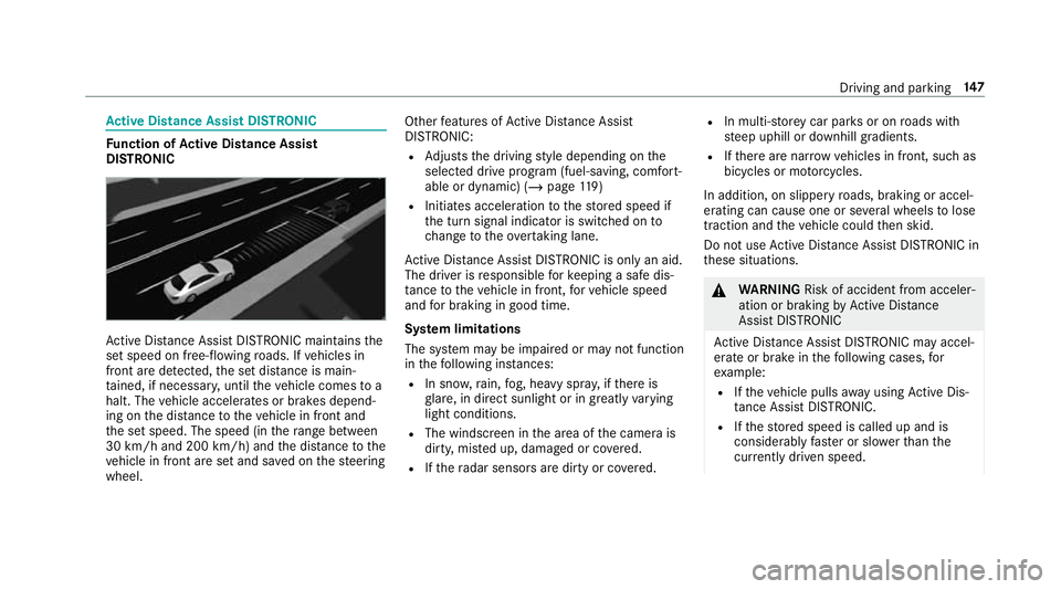
tive Di stance Assist DISTRO NICFu
nction of Active Di stance Assist
DISTRO NIC Ac
tive Dis tance Assi stDISTRONIC maintains the
set speed on free-flowing roads. If vehicles in
front are de tected, the set dis tance is main‐
ta ined, if necessar y,until theve hicle comes to a
halt. The vehicle accelerates or brakes depend‐
ing on the dis tance totheve hicle in front and
th e set speed. The speed (in thera nge between
30 km/h and 200 km/h) and the dis tance tothe
ve hicle in front are set and sa ved on thesteering
wheel. Other
features of Active Dis tance Assi st
DISTRONIC:
R Adjusts the driving style depending on the
selected drive program (fuel-saving, comfort‐
able or dynamic) (/ page119)
R Initiates ac celerationtothestored speed if
th e turn signal indicator is switched on to
ch ange totheove rtaking lane.
Ac tive Dis tance Assi stDISTRONIC is only an aid.
The driver is responsible forke eping a safe dis‐
ta nce totheve hicle in front, forve hicle speed
and for braking in good time.
Sy stem limitations
The sy stem may be impaired or may not function
in thefo llowing ins tances:
R In sno w,rain, fog, heavy spr ay, if there is
gl are, in direct sunlight or in greatlyvarying
light conditions.
R The windsc reen in the area of the camera is
dirty, mis ted up, damaged or co vered.
R Ifth era dar sensors are dirty or co vered. R
In multi- stor ey car pa rks or on roads with
st eep uphill or downhill gradients.
R Ifth ere are nar rowvehicles in front, such as
bicycles or mo torcyc les.
In addition, on slippery roads, braking or accel‐
erating can cause one or se veral wheels tolose
traction and theve hicle could then skid.
Do not use Active Dis tance Assi stDISTRONIC in
th ese situations. &
WARNING Risk of accident from acceler‐
ation or braking byActive Dis tance
Assi stDISTRONIC
Ac tive Dis tance Assi stDISTRONIC may accel‐
erate or brake in thefo llowing cases, for
ex ample:
R Ifth eve hicle pulls away using Active Dis‐
ta nce Assi stDISTRONIC.
R Ifth estored speed is called up and is
considerably faster or slo werth an the
cur rently driven speed. Driving and pa
rking 147
Page 165 of 409
If
AT TENTION ASSIST is unable tocalculate the
attention le vel and cannot issue a warning, the
System suspended messageappears.
If AT TENTION ASSIST is deactivated, theé
symbol appears in the assis tance graphic in the
instrument display when the engine is running.
AT TENTION ASSIST is activated automatically
when the engine is re-sta rted. The last selected
sensitivity le velre mains stored.
Sy stem limitations
AT TENTION ASSIST is active in the 60 km/h to
200 km/h speed range.
The functionality of ATTENTION ASSIST is
re stricted, and warnings may be dela yed or not
occur at all in thefo llowing situations:
R Ifyo u ha vebeen driving for less than appr ox‐
imately 30 minutes.
R Ifth ero ad condition is poor (une venro ad
sur face or po tholes).
R Ifth ere is a strong side wind.
R Ifyo u adopt a sporty driving style (high cor‐
nering speeds or high rates of acceleration).
R Ifth e time has been set incor rectl y. R
In active driving situations, if youch ange
lanes and vary your speed frequentl y.
The ATTENTION ASSIST tiredness or alertness
assessment is dele ted and restar ted when con‐
tinuing the journey in thefo llowing situations:
R Ifyo u swit choff the engine.
R Ifyo u unfas tenyo ur seat belt and open the
driver's door (e.g. changing drivers or taking
a break).
Setting ATTENTION ASSI ST
Multimedia sy stem:
4 Vehicle 5
k Assistance
5 ATTENTION ASSIST
Setting options #
Select Standard, SensitiveorOff.
Suggesting a rest area #
Select Suggest rest area . #
Activate Oor deacti vate the function ª.
If AT TENTION ASSIST de tects fatigue or
increasing la ckof attention, it suggests a
re st area in the vicinit y. #
Select a sugges tedre st area: you are gui‐
ded tothe selected rest area. Blind Spot Assist
Fu
nction of Blind Spot Assist
Blind Spot Assist uses two lateral, rear-facing
ra dar sensors tomonitor the area up to3 m
behind and next toyour vehicle.
If a vehicle is de tected at speeds ab ove appr ox‐
imately 30 km/h and this vehicle subsequently
enters the monitoring range next to yourvehicle,
th ewa rning lamp in the outside mir ror lights up
re d.
If a vehicle is de tected close tothe side of your
ve hicle, there dwa rning lamp in the outside mir‐
ro rflashes. If you swit chon the turn signal indi‐
cator in the cor responding direction, a warning
to ne sounds once. If the turn signal indicator
re mains switched on, all other de tected vehicles
are indicated only bytheflashing of thered
wa rning lamp.
If yo uove rtake a vehicle quickl y,no warning is
given. 16 2
Driving and pa rking
Page 167 of 409
Whe
ther a warning is issued and when this
occurs also depends on the selected sensitivity
setting (s tandard or adaptive).
Lane Keeping Assist can neither reduce therisk
of an accident if youfa ilto adapt your driving
st yle nor override the la wsof ph ysics. It cannot
ta ke into account road, weather or traf fic condi‐
tions. Lane Keeping Assist is only an aid. You are
re sponsible for maintaining a safe dis tance to
th eve hicle in front, forve hicle speed, for braking
in good time and forst ay ing in lane.
Lane Keeping Assist is available in the speed
ra nge between 60 km/h and 200 km/h.
Sy stem limitations
The sy stem may be impaired or may not function
in thefo llowing situations:
R Ifth ere is poor visibility, e.g. due toinsuf fi‐
cient illumination of thero ad, if there are
highly variable shade conditions or in rain,
sno w,fog or heavy spr ay.
R Ifth ere is glare, e.g. from oncoming traf fic,
th e sun or reflections. R
Ifth e windscreen in the area of the multi‐
function camera is dirty, or if the camera is
mis ted up, damaged or co vered.
R Ifth ere are no lane markings, or se veral
unclear lane markings are present for one
lane, e.g. around roadwor ks.
R Ifth e lane markings are worn, dark or cov‐
ered.
R Ifth e dis tance totheve hicle in front is too
short and thus the lane markings cann otbe
de tected.
R Ifth e lane markings change quickl y,e.g.
lanes branch off, cross one ano ther or
mer ge.
R Ifth e car riag ewa y is very nar row and wind‐
ing.
Sensitivity of Lane Keeping Assist
Wi th th eSt andard or Adaptive setting, you can
influence when thewa rning vibration of Lane
Ke eping Assist take s place. In bo
th theSt andard and Adaptive settings, no
wa rning vibration occurs in thefo llowing situa‐
tions:
R You ha veswitched on the turn signal indica‐
to r.
R A driving sa fety sy stem inter venes, su chas
ABS, BAS or ESP ®
.
In theAd aptive setting, there will also be no
wa rning vibration in thefo llowing situations:
R The vehicle is accelerated or braked consid‐
erabl y.
R Yousteer actively, e.g. swer vetoavoid an
obs tacle or change lane quickl y.
R You cut the corner on a sharp bend. Ve
hicle towing instructions
The vehicle is not suitable forth e use of tow bar
sy stems that are used forflat towing or ding hy
to wing, forex ample. Attach ing and using tow bar
sy stems can lead todamage on theve hicle.
When you are towing a vehicle with tow bar sys‐
te ms, safe driving characteristics cannot be 16 4
Driving and pa rking
Page 350 of 409
Key
Display messages
Possible causes/consequences and M
MSolutions
 Insert key *T
hekey is not de tected continuously.
De tection of theke y is temp orarily malfunctioning or faulty. A warning tone will also sound. #
Inse rttheke y in the ignition lock and turn tothe desired key position. #
Consult a qualified specialist workshop.
Á Key not detected (red dis‐
play message) *T
hekey cannot be de tected and may no longer be in theve hicle.
The key is no lon ger in theve hicle and you swit choff the engine:
R You can no lon gerst art the engine.
R You cannot centrally lock theve hicle. #
Ensure that theke y is in theve hicle.
If th eke y de tection function has a malfunction due toast ro ng radio signal source: #
Pull over and stop theve hicle safely as soon as possible, paying attention toroad and traf fic conditions. #
Place theke y in the slot forst arting the engine with theke y (/ page113).
Á
Replace key *T
hekey needs tobe replaced. #
Consult a qualified specialist workshop. Display messages and
warning/indicator lamps 347
Page 402 of 409
Tr
ip
Menu (on-board computer) .................. 174
Tr ip computer
Displaying ............................................ 174
Re setting ............................................. 175
Tr ip distance ............................................ .174
Displ aying ............................................ 174
Re setting ............................................. 175
Tr ip me ter
see Trip dis tance
Tu rn signal indicator
see Turn signal lights
Tu rn signal lights ....................................... 99
Switching on/off ................................... 99
Tw o phone mode
see Second telephone
Ty re inflation compressor
see TIREFIT kit
Ty re pressure ........................................... 287
Checking (ty repressure monitoring
sy stem) ............................................... 288
No tes .................................................. 286 Re
starting the tyre pressure monitor‐
ing sy stem ...........................................2 89
TIREFIT kit .......................................... .268
Ty re pressure monitoring sy stem
(function) ............................................. 287
Ty re pressure table .............................. 287
Ty re pressure moni toring sy stem
Checking the tyre pressure ................. 288
Fu nction .............................................. 287
Re starting ............................................ 289
Te ch nical da ta..................................... 289
Ty re pressure table ................................. 287
Ty re temp erature
Ty re pressure monitoring sy stem
(function) ............................................. 287
Ty re tread ................................................. 285
Ty re-change tool kit
Overview ............................................ .297
Ty res
Checking ............................................ .285
Che cking the tyre pressure (tyre
pressure monitoring sy stem) ............... 288
Fitting .................................................. 301
Flat tyre ............................................... 266 Inter
changing ...................................... 296
MOExtended tyres .............................. .267
No ise .................................................. .285
No tes on fitting ................................... 293
Re moving ............................................ 300
Re placing .................................... 293, 297
Re starting the tyre pressure monitor‐
ing sy stem ...........................................2 89
Selection ............................................. 293
Snow chains ........................................ 285
St oring .................................................2 97
TIREFIT kit ...........................................2 68
Ty re pressure (N otes) .......................... 286
Ty re pressure monitoring sy stem
(function) ............................................. 287
Ty re pressure table .............................. 287
Un usual handling characteristics ........ 285 U
Un its of measurement
Setting ................................................ .191
Un locking setting ...................................... 57
USB devices Connecting .......................................... 235 Index
399