MERCEDES-BENZ AMG GT ROADSTER 2019 Owner's Manual
Manufacturer: MERCEDES-BENZ, Model Year: 2019, Model line: AMG GT ROADSTER, Model: MERCEDES-BENZ AMG GT ROADSTER 2019Pages: 298, PDF Size: 7.9 MB
Page 251 of 298
Where will I find...?
Reflective safety jacket
Removing/replacing the reflective
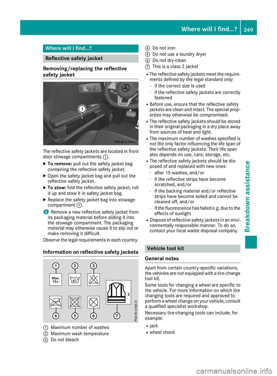
safety jacket The reflective safety jackets are located in front
door stowage compartments 0043.
X To remove: pull out the safety jacket bag
containing the reflective safety jacket.
X Open the safety jacket bag and pull out the
reflective safety jacket.
X To stow: fold the reflective safety jacket, roll
it up and stow it in safety jacket bag.
X Replace the safety jacket bag into stowage
compartment 0043.
i Remove a new reflective safety jacket from
its packaging material before sliding it into
the stowage compartment. The packaging
material may otherwise cause it to slip out or
make removing it difficult.
Observe the legal requirements in each country.
Information on reflective safety jackets 0043
Maximum number of washes
0044 Maximum wash temperature
0087 Do not bleach 0085
Do not iron
0083 Do not use a laundry dryer
0084 Do not dry-clean
006B This is a class 2 jacket
R The reflective safety jackets meet the require-
ments defined by the legal standard only:
- if the correct size is used
- if the reflective safety jackets are correctly
fastened
R Before use, ensure that the reflective safety
jackets are clean and intact. The special prop-
erties may otherwise be compromised.
R The reflective safety jackets should be stored
in their original packaging in a dry place away
from sources of heat and light.
R The maximum number of washes specified is
not the only factor influencing the life span of
the reflective safety jackets. Their life span
also depends on use, care, storage, etc.
R The reflective safety jackets should be dis-
posed of and replaced with new ones:
- after 15 washes, and/or
- if the reflective strips have become
scratched, and/or
- if the backing material and/or reflective
strips have become soiled and cannot be
cleaned off, and/or
- if the fluorescence has faded e.g. due to the
effects of sunlight
R Dispose of reflective safety jackets in an envi-
ronmentally responsible manner. To do so,
contact your local waste disposal company. Vehicle tool kit
General notes Apart from certain country-specific variations,
the vehicles are not equipped with a tire-change
tool kit.
Some tools for changing a wheel are specific to the vehicle. For more information on which tire
changing tools are required and approved to
perform a wheel change on your vehicle, consult
a qualified specialist workshop.
Necessary tire-changing tools can include, for
example:
R jack
R wheel chock Where will I find...?
249Breakdown assistance
Page 252 of 298
R
lug wrench
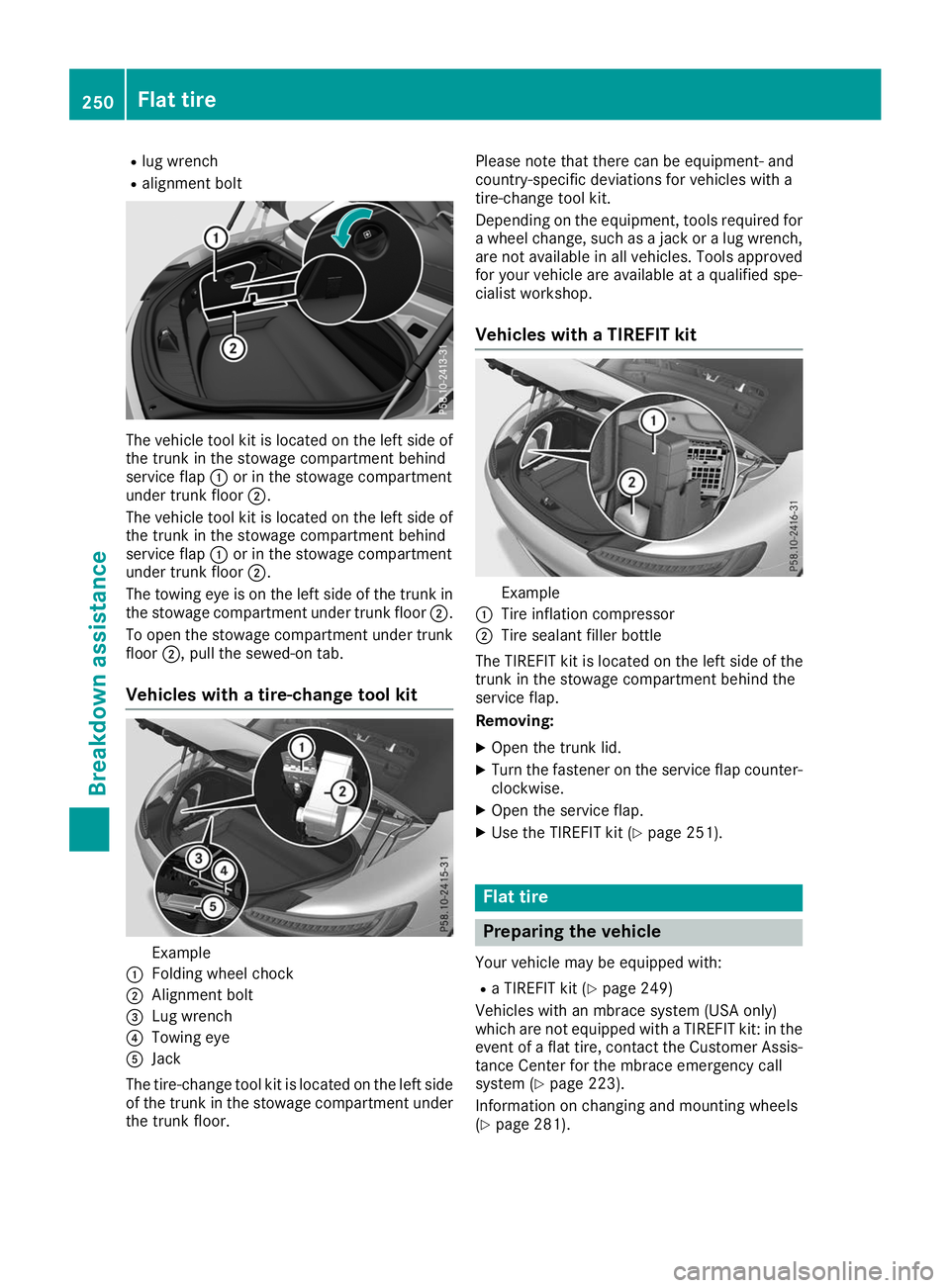
R alignment bolt The vehicle tool kit is located on the left side of
the trunk in the stowage compartment behind
service flap 0043or in the stowage compartment
under trunk floor 0044.
The vehicle tool kit is located on the left side of the trunk in the stowage compartment behind
service flap 0043or in the stowage compartment
under trunk floor 0044.
The towing eye is on the left side of the trunk in
the stowage compartment under trunk floor 0044.
To open the stowage compartment under trunk floor 0044, pull the sewed-on tab.
Vehicles with a tire-change tool kit Example
0043 Folding wheel chock
0044 Alignment bolt
0087 Lug wrench
0085 Towing eye
0083 Jack
The tire-change tool kit is located on the left side of the trunk in the stowage compartment under the trunk floor. Please note that there can be equipment- and
country-specific deviations for vehicles with a
tire-change tool kit.
Depending on the equipment, tools required for
a wheel change, such as a jack or a lug wrench, are not available in all vehicles. Tools approved
for your vehicle are available at a qualified spe-
cialist workshop.
Vehicles with a TIREFIT kit Example
0043 Tire inflation compressor
0044 Tire sealant filler bottle
The TIREFIT kit is located on the left side of the
trunk in the stowage compartment behind the
service flap.
Removing:
X Open the trunk lid.
X Turn the fastener on the service flap counter-
clockwise.
X Open the service flap.
X Use the TIREFIT kit (Y page 251). Flat tire
Preparing the vehicle
Your vehicle may be equipped with: R a TIREFIT kit (Y page 249)
Vehicles with an mbrace system (USA only)
which are not equipped with a TIREFIT kit: in the event of a flat tire, contact the Customer Assis-
tance Center for the mbrace emergency call
system (Y page 223).
Information on changing and mounting wheels
(Y page 281). 250
Flat tireBreakdown assistance
Page 253 of 298
X
Stop the vehicle on solid, non-slippery and
level ground, as far away as possible from
traffic.
X Switch on the hazard warning lamps.
X Secure the vehicle against rolling away
(Y page 127).
X If possible, bring the front wheels into the
straight-ahead position.
X Switch off the engine.
X With KEYLESS-GO start function or vehi-
cles with KEYLESS-GO: open the driver's
door.
The vehicle electronics are now in key posi-
tion 0092. This is the same as the key having
been removed.
or X Remove the SmartKey from the ignition lock.
X Make sure that the passengers are not endan-
gered as they do so. Make sure that no one is
near the danger area while a wheel is being
changed. Anyone who is not directly assisting in the wheel change should, for example,
stand behind the barrier.
X Get out of the vehicle. Pay attention to traffic
conditions when doing so.
X Close the driver's door. TIREFIT kit
Important safety notes TIREFIT is a tire sealant.
You can use TIREFIT to seal punctures of up to
0.16 in (4 mm), particularly those in the tire
tread. You can use TIREFIT at outside tempera-
tures down to 00F84 ‡ (00F820 †). G
WARNING
In the following situations, the tire sealant is
unable to provide sufficient breakdown assis- tance, as it is unable to seal the tire properly:
R there are cuts or punctures in the tire larger
than those mentioned above.
R the wheel rim is damaged.
R you have driven at very low tire pressures or
on a flat tire.
There is a risk of an accident.
Do not drive the vehicle. Contact a qualified
specialist workshop. G
WARNING
The tire sealant is harmful and causes irrita-
tion. It must not come into contact with your
skin, eyes or clothing or be swallowed. Do not inhale TIREFIT fumes. Keep tire sealant away
from children. There is a risk of injury.
If you come into contact with the tire sealant,
observe the following:
R Rinse off the tire sealant from your skin
immediately with water.
R If the tire sealant comes into contact with
your eyes, immediately rinse them thor-
oughly with clean water.
R If tire sealant is swallowed, immediately
rinse your mouth out thoroughly and drink
plenty of water. Do not induce vomiting,
and seek medical attention immediately.
R Immediately change out of clothing which
has come into contact with tire sealant.
R If an allergic reaction occurs, seek medical
attention immediately.
! Do not operate the tire inflation compressor
for longer than ten minutes at a time without a break. It may otherwise overheat.
The tire inflation compressor can be operatedagain once it has cooled down.
Comply with the manufacturer's safety instruc-
tions on the tire inflation compressor label and
on the tire sealant bottle.
Using the TIREFIT kit X
Do not remove any foreign objects which have
penetrated the tire, e.g. screws or nails.
X Remove the tire sealant bottle, the accompa-
nying TIREFIT sticker and the tire inflation
compressor from the stowage compartment
in the trunk (Y page 249). Flat tire
251Breakdown assistance Z
Page 254 of 298
X
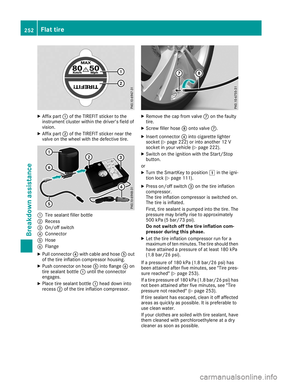
Affix part 0043of the TIREFIT sticker to the
instrument cluster within the driver's field of
vision.
X Affix part 0044of the TIREFIT sticker near the
valve on the wheel with the defective tire. 0043
Tire sealant filler bottle
0044 Recess
0087 On/off switch
0085 Connector
0083 Hose
0084 Flange
X Pull connector 0085with cable and hose 0083out
of the tire inflation compressor housing.
X Push connector on hose 0083into flange 0084on
tire sealant bottle 0043until the connector
engages.
X Place tire sealant bottle 0043head down into
recess 0044of the tire inflation compressor. X
Remove the cap from valve 006Bon the faulty
tire.
X Screw filler hose 006Conto valve 006B.
X Insert connector 0085into cigarette lighter
socket (Y page 222) or into another 12 V
socket in your vehicle (Y page 222).
X Switch on the ignition with the Start/Stop
button.
or X Turn the SmartKey to position 0047in the igni-
tion lock (Y page 111).
X Press on/off switch 0087on the tire inflation
compressor.
The tire inflation compressor is switched on.
The tire is inflated.
First, tire sealant is pumped into the tire. The
pressure may briefly rise to approximately
500 kPa (5 bar/73 psi).
Do not switch off the tire inflation com-
pressor during this phase.
X Let the tire inflation compressor run for a
maximum of ten minutes. The tire should then have attained a pressure of at least 180 kPa
(1.8 bar/26 psi).
If a pressure of 180 kPa (1.8 ba r/26 psi) has
been at tained after five minutes, see "Tire pres-
sure reached" (Y page 253).
If a tire pressure of 180 kPa (1.8 bar/26 psi) has not been attained after five minutes, see "Tire
pressure not reached" (Y page 253).
If tire sealant has escaped, clean it off affected
areas as quickly as possible. It is preferable to
use clean water.
If your clothes are soiled with tire sealant, have them cleaned with perchloroethylene at a dry
cleaner as soon as possible. 252
Flat tireBreakdown assistance
Page 255 of 298
Tire pressure not reached
If a pressure of 180 kPa (1.8 bar/26 psi) has not
been attained after five minutes:
X Switch off the tire inflation compressor.
X Unscrew the filler hose from the valve of the
faulty tire.
Tire sealant may escape when the filler hose is
unscrewed.
X Very slowly drive forwards or reverse approx-
imately 30 ft (10 m).
X Pump up the tire again.
After a maximum of ten minutes, the tire pres- sure must be at least 180 kPa (1.8 ba r/
26 psi). G
WA
RNING
If the required tire pressure is not reached
after the specified time, the tire is too badly
damaged. The tire sealant cannot repair the
tire in this instance. Damaged tires and a tire pressure that is too low can significantly
impair the vehicle's braking and driving char-
acteristics. There is a risk of accident.
Do not continue driving. Contact a qualified
specialist workshop.
Tire pressure reached G
WARNING
A tire temporarily sealed with tire sealant
impairs the driving characteristics and is not
suitable for higher speeds. There is a risk of
accident.
You should therefore adapt your driving style
accordingly and drive carefully. Do not exceed the specified maximum speed with a tire that
has been repaired using tire sealant.
The maximum permissible speed for a tire
sealed with tire sealant is 50 mph (80 km/h).
The upper part of the TIREFIT sticker must be
affixed to the instrument cluster in the driver's
field of vision.
! Residue from the tire sealant may come out
of the filler hose after use. This could cause
stains.
Therefore, place the filler hose in the plastic
bag which contained the TIREFIT kit. H
Environmental note
Have the used tire sealant bottle disposed of
professionally, e.g. at a qualified specialist
workshop.
If a tire pressure of 180 kPa (1.8 ba r/26 psi) has
been attained after five minutes:
X Switch off the tire inflation compressor.
X Unscrew the filler hose from the valve of the
faulty tire.
Tire sealant may escape when the filler hose is unscrewed.
X Stow the tire sealant bottle and the tire infla-
tion compressor.
X Pull away immediately.
X Stop after driving for approximately ten
minutes and check the tire pressure with the
tire inflation compressor.
The tire pressure must now be at least
130 kPa (1.3 bar/19 psi). G
WARNING
If the required tire pressure is not reached
after driving for a short period, the tire is too
badly damaged. The tire sealant cannot repair the tire in this instance. Damaged tires and a
tire pressure that is too low can significantly
impair the vehicle's braking and driving char-
acteristics. There is a risk of accident.
Do not continue driving. Contact a qualified
specialist workshop.
i In cases such as the one mentioned above,
contact an authorized Mercedes-Benz Cen-
ter. Or call 1-800-FOR-MERCedes (in the
USA) or 1-800-387-0100 (in Canada).
X Correct the tire pressure if it is still at least
130 kPa (1.3 bar/19 psi). See the Tire and
Loading Information placard on the driver's
side B-pillar or the tire pressure table in the
fuel filler flap for values.
X To increase the tire pressure: switch on the
tire inflation compressor. Flat tire
253Breakdown assistance Z
Page 256 of 298
X
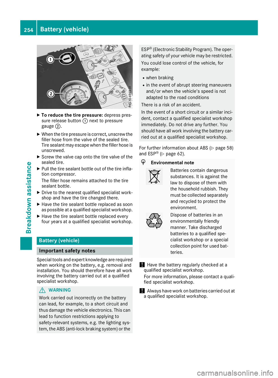
To reduce the tire pressure: depress pres-
sure release button 0043next to pressure
gauge 0044.
X When the tire pressure is correct, unscrew the
filler hose from the valve of the sealed tire.
Tire sealant may escape when the filler hose is unscrewed.
X Screw the valve cap onto the tire valve of the
sealed tire.
X Pull the tire sealant bottle out of the tire infla-
tion compressor.
The filler hose remains attached to the tire
sealant bottle.
X Drive to the nearest qualified specialist work-
shop and have the tire changed there.
X Have the tire sealant bottle replaced as soon
as possible at a qualified specialist workshop.
X Have the tire sealant bottle replaced every
four years at a qualified specialist workshop. Battery (vehicle)
Important safety notes
Special tools and expert knowledge are required
when working on the battery, e.g. removal and
installation. You should therefore have all work
involving the battery carried out at a qualified
specialist workshop. G
WARNING
Work carried out incorrectly on the battery
can lead, for example, to a short circuit and
thus damage the vehicle electronics. This can lead to function restrictions applying to
safety-relevant systems, e.g. the lighting sys- tem, the ABS (anti-lock braking system) or the ESP
®
(Electronic Stability Program). The oper-
ating safety of your vehicle may be restricted.
You could lose control of the vehicle, for
example:
R when braking
R in the event of abrupt steering maneuvers
and/or when the vehicle's speed is not
adapted to the road conditions
There is a risk of an accident.
In the event of a short circuit or a similar inci-
dent, contact a qualified specialist workshop
immediately. Do not drive any further. You
should have all work involving the battery car- ried out at a qualified specialist workshop.
For further information about ABS (Y page 58)
and ESP ®
(Y page 62). H
Environmental note Batteries contain dangerous
substances. It is against the
law to dispose of them with
the household rubbish. They
must be collected separately
and recycled to protect the
environment. Dispose of batteries in an
environmentally friendly
manner. Take discharged
batteries to a qualified spe-
cialist workshop or a special
collection point for used bat-
teries.
! Have the battery regularly checked at a
qualified specialist workshop.
For more information, please contact a quali- fied specialist workshop.
! Always have work on batteries carried out at
a qualified specialist workshop. 254
Battery (vehicle)Breakdo
wn assis tance
Page 257 of 298
Should it, in exceptional circumstances, be
absolutely necessary to disconnect the 12-
volt battery yourself, please observe the fol-
lowing:
R Secure the vehicle to prevent it from rolling
away.
R Switch off the ignition.
R Disconnect the negative terminal first and
then the positive terminal.
The transmission is locked in position 005D
after disconnecting the battery.
After the work has been done, install the bat-
tery and replace the cover of the positive ter- minal clamp firmly.
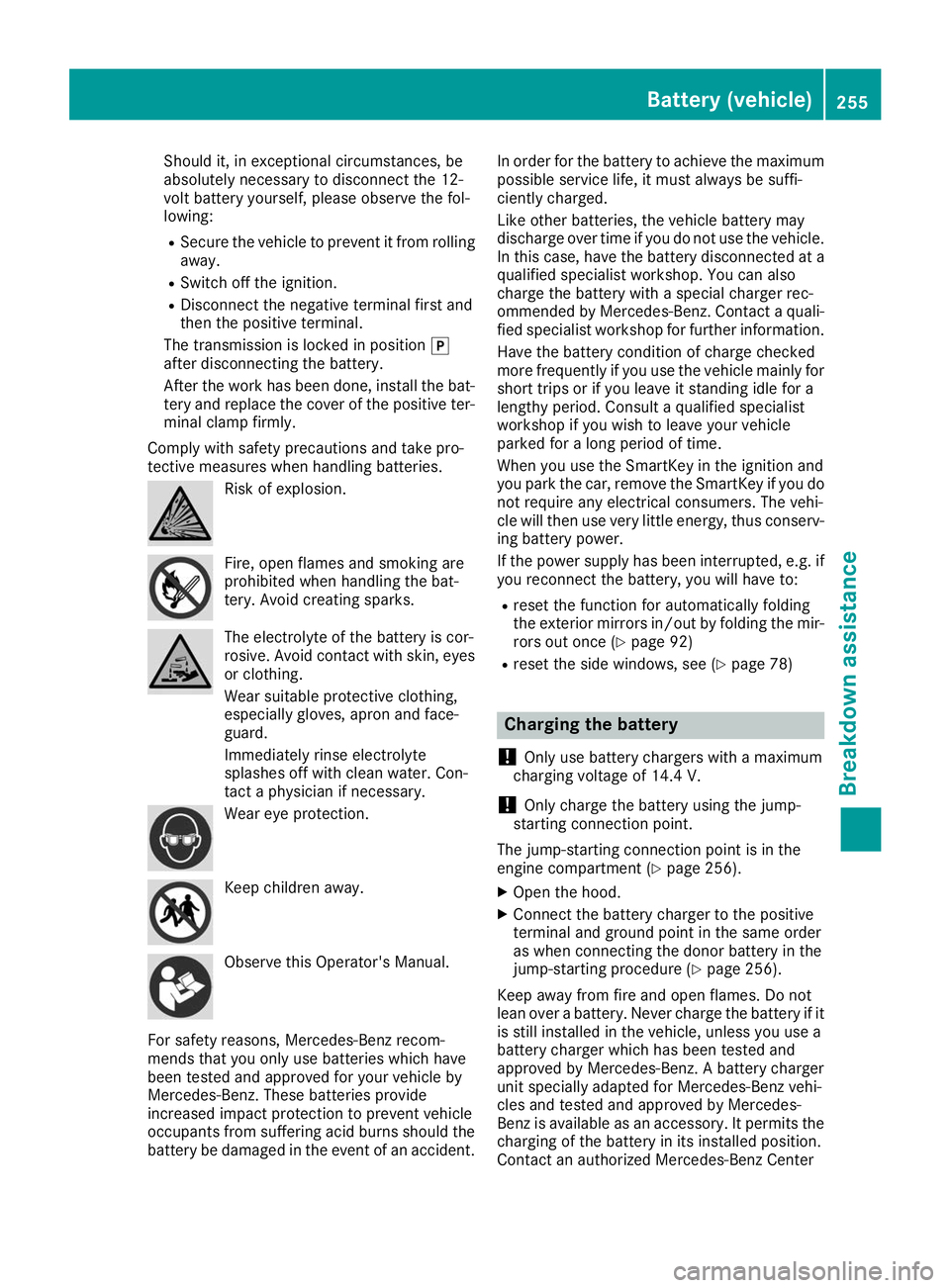
Comply with safety precautions and take pro-
tective measures when handling batteries. Risk of explosion.
Fire, open flames and smoking are
prohibited when handling the bat-
tery. Avoid creating sparks.
The electrolyte of the battery is cor-
rosive. Avoid contact with skin, eyes
or clothing.
Wear suitable protective clothing,
especially gloves, apron and face-
guard.
Immediately rinse electrolyte
splashes off with clean water. Con-
tact a physician if necessary. Wear eye protection.
Keep children away.
Observe this Operator's Manual.
For safety reasons, Mercedes-Benz recom-
mends that you only use batteries which have
been tested and approved for your vehicle by
Mercedes-Benz. These batteries provide
increased impact protection to prevent vehicle
occupants from suffering acid burns should the battery be damaged in the event of an accident. In order for the battery to achieve the maximum
possible service life, it must always be suffi-
ciently charged.
Like other batteries, the vehicle battery may
discharge over time if you do not use the vehicle.In this case, have the battery disconnected at a
qualified specialist workshop. You can also
charge the battery with a special charger rec-
ommended by Mercedes-Benz. Contact a quali- fied specialist workshop for further information.
Have the battery condition of charge checked
more frequently if you use the vehicle mainly for
short trips or if you leave it standing idle for a
lengthy period. Consult a qualified specialist
workshop if you wish to leave your vehicle
parked for a long period of time.
When you use the SmartKey in the ignition and
you park the car, remove the SmartKey if you do not require any electrical consumers. The vehi-
cle will then use very little energy, thus conserv-
ing battery power.
If the power supply has been interrupted, e.g. if
you reconnect the battery, you will have to:
R reset the function for automatically folding
the exterior mirrors in/out by folding the mir-
rors out once (Y page 92)
R reset the side windows, see (Y page 78) Charging the battery
! Only use battery chargers with a maximum
charging voltage of 14.4 V.
! Only
charge the battery using the jump-
starting connection point.
The jump-starting connection point is in the
engine compartment (Y page 256).
X Open the hood.
X Connect the battery charger to the positive
terminal and ground point in the same order
as when connecting the donor battery in the
jump-starting procedure (Y page 256).
Keep away from fire and open flames. Do not
lean over a battery. Never charge the battery if it is still installed in the vehicle, unless you use a
battery charger which has been tested and
approved by Mercedes-Benz. A battery charger
unit specially adapted for Mercedes-Benz vehi-
cles and tested and approved by Mercedes-
Benz is available as an accessory. It permits the
charging of the battery in its installed position.
Contact an authorized Mercedes-Benz Center Battery (vehicle)
255Breakdown assistance Z
Page 258 of 298
for further information and availability. Read the
battery charger's operating instructions before
charging the battery.
Do not charge a battery which has been
removed at low temperatures with a battery
charger. Allow the battery to warm up gently
first, if necessary. Otherwise, the service life can be shortened and the starting characteristics
impaired, especially at low temperatures. Replacing the 12 V battery
Observe the notes on the 12 V battery
(Y page 254).
Mercedes-Benz recommends that you have the
12 V battery replaced at a qualified specialist
workshop, e.g. at an authorized Mercedes-Benz
Center.
If you want to replace the battery yourself,
observe the following notes:
R Always replace a defective battery with a bat-
tery which meets the specific requirements of
the vehicle. The vehicle is equipped with an AGM (Absorb-
ent Glass Mat) technology battery or a lith-
ium-ion battery. Full vehicle functionality is
only guaranteed with an AGM or lithium-ion
battery. For safety reasons, Mercedes-Benz
recommends that you only use batteries
which have been tested and approved for yourvehicle by Mercedes-Benz.
R Use detachable parts such as breather hoses,
angled connecting pieces or terminal covers
from the battery which is to be replaced.
R Make sure that the vent hose is always con-
nected to the original opening on the battery
side.
Install any existing or supplied stop plugs.
Otherwise, gases or battery acid could
escape.
R Make sure that the detachable parts are con-
nected again in the same way. Jump-starting
X For the jump-starting procedure, use only the jump-starting connection point in the engine com-
partment, consisting of a positive terminal and a ground point.
! Avoid repeated and lengthy starting attempts. Otherwise, the catalytic converter could be
damaged by the non-combusted fuel.
X Do not start the vehicle using a rapid charging device.
If your vehicle's battery is discharged, the engine can be jump-started from another vehicle or
from a donor battery using jumper cables.
The battery is not accessible in all vehicles. If the other vehicle's battery is not accessible, jump-start the vehicle using a donor battery or a jump-starting device.
Observe the following during the jump-starting procedure:
R the jumper cables must not come into contact with parts that can move when the engine is
running, such as the V-belt pulley or the fan.
R non-insulated parts of the terminal clamps must not come into contact with other metal parts
while the jumper cables are connected to the battery and the jump-starting connection point.
R only use jumper cables that are not damaged and have a sufficient cross-section and insulated
terminal clamps.
R jump-starting may be performed only using batteries with a nominal voltage of 12 V.
R you may only jump-start the vehicle when the engine and exhaust system are cold.
R the vehicles must not touch each other.
R If the battery is fully discharged, leave the battery that is being used to jump-start connected for
a few minutes before attempting to start. This charges the battery slightly. 256
Jump-startingBreakdown assistance
Page 259 of 298
X
Secure the vehicle by applying the electric parking brake.
X Shift the transmission to position 005D.
X Make sure the ignition and all electrical consumers are switched off.
All indicator lamps in the instrument cluster must be off. When using the SmartKey, turn the
SmartKey to position 0092in the ignition lock and remove it (Y page 111).
X Open the hood.
i Right-hand-drive vehicle:
the jump-starting connection points may be located on the other
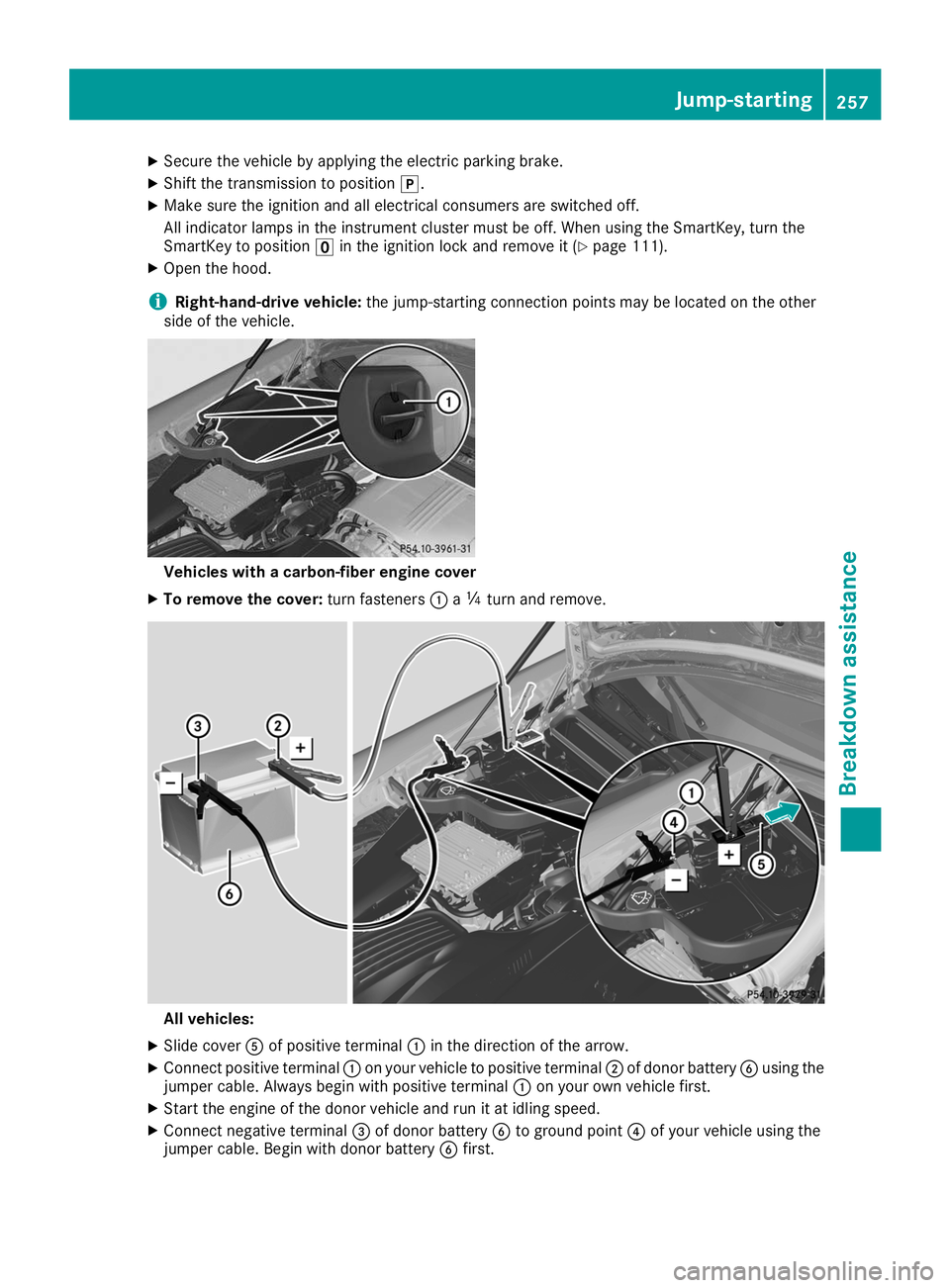
side of the vehicle. Vehicles with a carbon-fiber engine cover
X To remove the cover: turn fasteners0043a00C4 turn and remove. All vehicles:
X Slide cover 0083of positive terminal 0043in the direction of the arrow.
X Connect positive terminal 0043on your vehicle to positive terminal 0044of donor battery 0084using the
jumper cable. Always begin with positive terminal 0043on your own vehicle first.
X Start the engine of the donor vehicle and run it at idling speed.
X Connect negative terminal 0087of donor battery 0084to ground point 0085of your vehicle using the
jumper cable. Begin with donor battery 0084first. Jump-starting
257Breakdown assistance Z
Page 260 of 298
X
Start the engine of your own vehicle.
X Let the engines run for several minutes.
X Before disconnecting the jumper cables, switch on an electrical consumer in your own vehicle,
e.g. the rear window heating or the lighting.
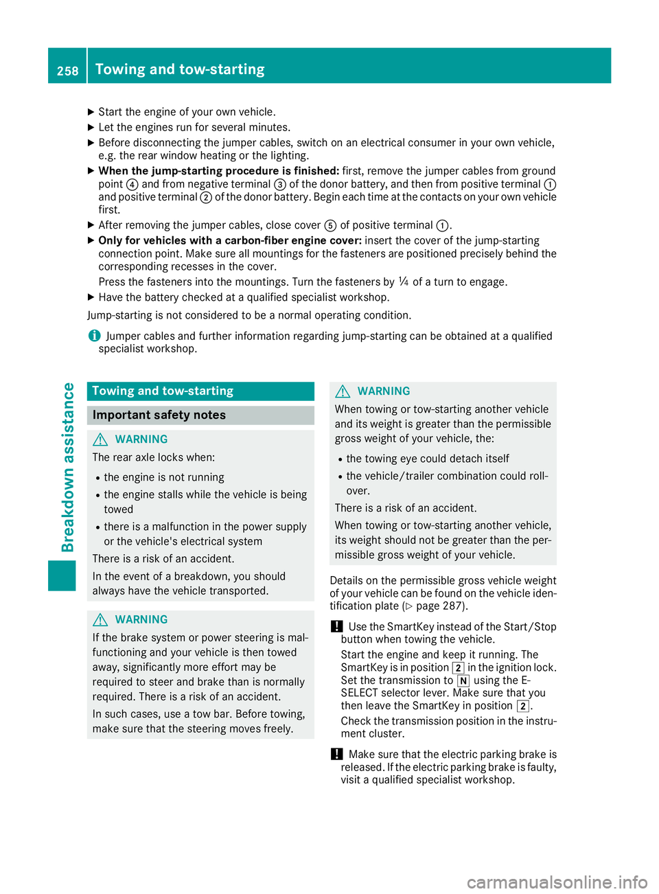
X When the jump-starting procedure is finished: first, remove the jumper cables from ground
point 0085and from negative terminal 0087of the donor battery, and then from positive terminal 0043
and positive terminal 0044of the donor battery. Begin each time at the contacts on your own vehicle
first.
X After removing the jumper cables, close cover 0083of positive terminal 0043.
X Only for vehicles with a carbon-fiber engine cover: insert the cover of the jump-starting
connection point. Make sure all mountings for the fasteners are positioned precisely behind the corresponding recesses in the cover.
Press the fasteners into the mountings. Turn the fasteners by 00C4of a turn to engage.
X Have the battery checked at a qualified specialist workshop.
Jump-starting is not considered to be a normal operating condition.
i Jumper cables and further information regarding jump-starting can be obtained at a qualified
specialist workshop. Towing and tow-starting
Important safety notes
G
WARNING
The rear axle locks when:
R the engine is not running
R the engine stalls while the vehicle is being
towed
R there is a malfunction in the power supply
or the vehicle's electrical system
There is a risk of an accident.
In the event of a breakdown, you should
always have the vehicle transported. G
WARNING
If the brake system or power steering is mal-
functioning and your vehicle is then towed
away, significantly more effort may be
required to steer and brake than is normally
required. There is a risk of an accident.
In such cases, use a tow bar. Before towing,
make sure that the steering moves freely. G
WARNING
When towing or tow-starting another vehicle
and its weight is greater than the permissible gross weight of your vehicle, the:
R the towing eye could detach itself
R the vehicle/trailer combination could roll-
over.
There is a risk of an accident.
When towing or tow-starting another vehicle,
its weight should not be greater than the per- missible gross weight of your vehicle.
Details on the permissible gross vehicle weight
of your vehicle can be found on the vehicle iden-
tification plate (Y page 287).
! Use the SmartKey instead of the Start/Stop
button when towing the vehicle.
Start the engine and keep it running. The
SmartKey is in position 0048in the ignition lock.
Set the transmission to 005Cusing the E-
SELECT selector lever. Make sure that you
then leave the SmartKey in position 0048.
Check the transmission position in the instru-
ment cluster.
! Make sure that the electric parking brake is
released. If the electric parking brake is faulty,
visit a qualified specialist workshop. 258
Towing and tow-startingBreakdown assistance