ECU MERCEDES-BENZ AMG GT S 2017 C190 Repair Manual
[x] Cancel search | Manufacturer: MERCEDES-BENZ, Model Year: 2017, Model line: AMG GT S, Model: MERCEDES-BENZ AMG GT S 2017 C190Pages: 290, PDF Size: 6.73 MB
Page 250 of 290
Jump-starting
For the jump-starting procedure, use only the jump-starting connection point in the engine com-
partment, consisting of a positive terminal and a ground point.
!Avoid repeated and lengthy starting attempts. Otherwise, the catalytic converter could be
damaged by the non-combusted fuel.
Do not start the vehicle using a rapid charging device. If your vehicle's battery is discharged, the
engine can be jump-started from another vehicle or from a second battery using jumper cables.
Observe the following points:
RThe battery is not accessible in all vehicles. If the other vehicle's battery is not accessible, jump-
start the vehicle using a second battery or a jump-starting device.
RYou may only jump-start the vehicle when the engine and exhaust system are cold.
ROnly jump-start from batteries with a 12 V voltage rating.
ROnly use jumper cables which have a sufficient cross-section and insulated terminal clamps.
RIf the battery is fully discharged, leave the battery that is being used to jump-start connected for
a few minutes before attempting to start. This charges the battery slightly.
RMake sure that the two vehicles do not touch.
Make sure that:
RThe jumper cables are not damaged.
RBare parts of the terminal clamp do not come into contact with other metal parts while the jumper
cables are connected to the battery.
RThe jumper cables cannot come into contact with parts which can move when the engine is
running, such as the V-belt pulley or the fan.
XSecure the vehicle by applying the electric parking brake.
XShift the transmission to position P.
XMake sure that the ignition is switched off. All indicator lamps in the instrument cluster must be
off. When using the SmartKey, turn the SmartKey to position 0in the ignition lock and remove it
(
Ypage 103).
XSwitch off all electrical consumers, e.g. rear window defroster, lighting, etc.
XOpen the hood.
Vehicles with carbon engine cover:
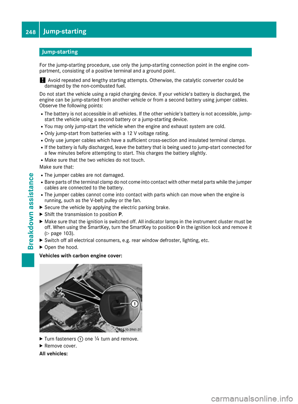
XTurn fasteners :one Õturn and remove.
XRemove cover.
All vehicles:
248Jump-starting
Breakdown assistance
Page 252 of 290
Towing and tow-starting
Important safety notes
GWARNING
The rear axle locks when:
Rthe engine is not running
Rthe engine stalls while the vehicle is being
towed
Rthere is a malfunction in the power supply
or the vehicle's electrical system
There is a risk of an accident.
In the event of a breakdown, you should
always have the vehicle transported.
GWARNING
If the brake system or power steering is mal-
functioning and your vehicle is then towed
away, significantly more effort may be
required to steer and brake than is normally
required. There is a risk of an accident.
In such cases, use a tow bar. Before towing,
make sure that the steering moves freely.
GWARNING
When towing or tow-starting another vehicle
and its weight is greater than the permissible
gross weight of your vehicle, the:
Rthe towing eye could detach itself
Rthe vehicle/trailer combination could roll-
over.
There is a risk of an accident.
When towing or tow-starting another vehicle,
its weight should not be greater than the per- missible gross weight of your vehicle.
Details on the permissible gross vehicle weight
of your vehicle can be found on the vehicle iden-
tification plate (
Ypage 280).
!Use the SmartKey instead of the Start/Stop
button when towing the vehicle.
Start the engine and keep it running. Turn the
SmartKey to position 2in the ignition. Set the
transmission to Nusing the E-SELECT lever.
Make sure that you then leave the SmartKey
in position 2. Check the transmission position in the instru-
ment cluster.
!Make sure that the electric parking brake is
released. If the electric parking brake is faulty,
visit a qualified specialist workshop.
!Secure the tow rope or tow bar to the towing
eye only. Otherwise, the vehicle could
become damaged.
!When COLLISION PREVENTION ASSIST
PLUS, DISTRONIC PLUS or the HOLD function
i
s activated, the vehicle brakes automatically
in certain situations.
To avoid damage to the vehicle, deactivate
these systems in the following or similar sit-
uations:
Rwhen towing the vehicle
Rin the car wash
!Do not use the towing eyes for recovery pur-
poses as this could damage the vehicle. If in
doubt, recover the vehicle with a crane.
!When towing, pull away slowly and
smoothly. If the tractive power is too high, the vehicles could be damaged.
!Shift the automatic transmission to Nand
do not open the driver's or front passenger's
door during towing. The automatic transmis-
sion may otherwise shift to position P, which
could damage both vehicles.
!Do not tow with sling-type equipment. This
could damage the vehicle.
!The vehicle can be towed a maximum of
30 miles (50km). The towing speed of 30 mph
(50 km/h) must not be exceeded.
If the vehicle has to be towed more than
30 miles (50km), the entire vehicle must be
raised and transported.
!Observe the transmission fluid temperature
(AMG menu) in the on-board computer when
towing. The transmission fluid temperature
must not exceed 250 ‡ (120 †). If this
occurs, you must stop to
wing immediately.
!Tow-starting the vehicle is not permitted.
The transmission may otherwise be damaged.
250Towing and tow-starting
Breakdown assistance
Page 254 of 290
XCheck the transmission position using the
indicatorinthe multifunction display
(
Ypage 110).
XRelease the brake pedal.
XRelease the electricparking brake.
XSwit ch on the hazard warning lamps
(Ypage 88).
In order to signal a change of direction when
to wing the veh icle with the hazard warning
lamps switched on, use the co mbination switch
as usual. Inthis case, only the indicator lamps
for the direction of travel flash. After resetting
the co mbination switch, the hazard warning
lamp starts flashing again.
Transporting the vehicle
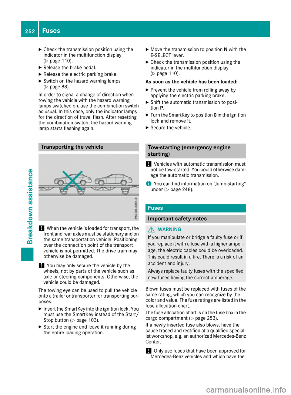
!When the veh icle isloaded for transport, the
front and rear axles must bestationary and on
the same transportation veh icle. Positioning
over the connection point of the transport
veh icle is not permitte d.The drive train may
otherwise be damaged.
!You may only secure the veh icle bythe
wheels, not byparts of the veh iclesuch as
axle or steering components. Otherwise, the
veh icle could bedamaged.
The to wingeye can beused to pullthe veh icle
onto a trailer or transporter for transporting pur- poses.
XIn sert the SmartKey into the ignition lock. You
must use the SmartKey instead of the Start/
St op button (
Ypage 103).
XStart the engine and leave itrunning during
the entire loading operation.
XMove the transmission to position Nwit h the
E-SELECT lever.
XCheck the transmission position using the
indicator in the multifunction display
(
Ypage 110).
As soon as the vehicle has been loaded:
XPrevent the vehicle from rolling away by
applying the electric parking brake.
XShift the automatic transmission to posi-
tion P.
XTurn the SmartKey to position 0in the ignition
lock and remove it.
XSecure the vehicle.
Tow-starting (emergency engine
starting)
!
Vehicles with automatic transmission must
not be tow-starte d.You could otherwise dam-
age the automatic transmission.
iYou can find information on "Jump-starting"
under (Ypage 248).
Fuses
Important safety notes
GWARNING
If you manipulate or bridge a faulty fuse or if
you replace itwith a fuse with a higher amper-
age, the electric cables could beoverloaded.
This could result ina fire. There is a risk of an
accident and injury.
Alwa ys replace faulty fuses with the specified
new fuses having the correct amperage.
Blo wn fuses must bereplaced with fuses of the
same rating, which you can recognize bythe
color and value. The fuse ratings are listed in the
fuse allocation chart.
The fuse allocation chart is on the fuse box in the
cargo compartment (
Ypage 253).
If a newly inserted fuse also blows, have the
cause traced and rectified at a qualified special-
ist workshop, e.g. an authorized Mercedes-Benz
Center.
!Only use fuses that have been approved for
Mercedes-Benz vehicles and which have the
252Fuses
Breakdown assistance
Page 255 of 290
correct fuse rating for the system concerned.
Otherwise, components or systems could be
damaged.
!Make sure that no moisture can enter the
fuse box when the cover is open.
!When closing the cover, make sure that it is
lying correctly on the fuse box. Moisture seep-
ing in or dirt could otherwise impair the oper-
ation of the fuses.
The fuses in your vehicle serve to close down
faulty circuits. If a fuse blows, all the compo-
nents on the circuit and their functions stop
operating.
Before changing a fuse
XSwitch off the engine.
XSwitch off all electrical consumers.
XOpen the driver's door.
The on-board electronics now have status 0.
This is the same as the SmartKey having been
removed.
or, if the SmartKey is inserted in the ignition
lock:
XRemove the SmartKey from the ignition lock.
XSecure the vehicle against rolling away
(Ypage 119).
All indicator lamps in the instrument cluster
must be off.
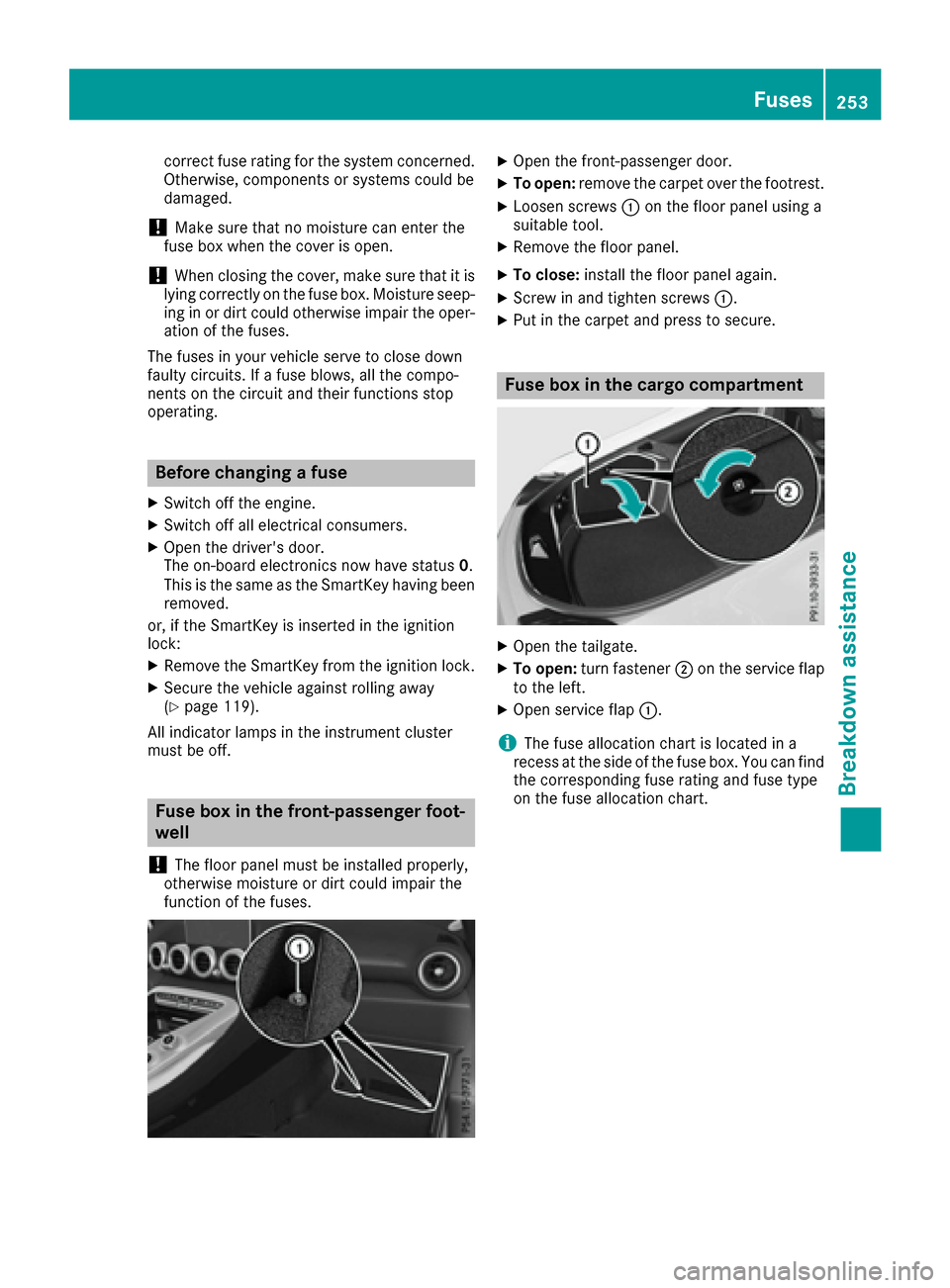
Fuse box in the front-passenger foot-
well
!
The floor panel must be installed properly,
otherwise moisture or dirt could impair the
function of the fuses.
XOpen the front-passenger door.
XTo open: remove the carpet over the footrest.
XLoosen screws :on the floor panel using a
suitable tool.
XRemove the floor panel.
XTo close: install the floor panel again.
XScrew in and tighten screws :.
XPut in the carpet and press to secure.
Fuse box in the cargo compartment
XOpen the tailgate.
XTo open:turn fastener ;on the service flap
to the left.
XOpen service flap :.
iThe fuse allocation chart is located in a
recess at the side of the fuse box. You can find
the corresponding fuse rating and fuse type
on the fuse allocation chart.
Fuses253
Breakdown assistance
Z
Page 256 of 290
Important safety notes
GWARNING
If wheels and tires of th ewrong siz eare used,
th ewhee lbrakes or suspension component s
may be damaged. Ther eis aris kof an acci-
dent.
Always replace wheels and tires wit hthose
that fulfill th especification sof th eoriginal
part .
When replacing wheels, mak esur eto use th e
correct:
Rdesignation
Rmodel
When replacing tires ,mak esur eto use th e
correct:
Rdesignation
Rmanufacturer
Rmodel
GWARNIN G
A flat tire severely impairs th edriving ,steer -
ing and braking characteristics of th evehicle.
Ther eis aris kof accident.
Tires without run-flat characteristics :
Rdo notdriv ewit h a flat tire.
Rimmediately replace th eflat tire wit hyour
emergenc yspar ewhee lor spar ewheel, or
consult aqualified specialist workshop.
Tires wit hrun-flat characteristics :
Rpay attention to theinformation and warn -
ing notice son MOExtended tires (tire swit h
run-flat characteristics).
Accessories that are no tapprove dfor your vehi-
cle by Mercedes-Ben zor are no tbein gused cor-
rectl ycan impair th eoperating safety.
Before purchasing and usin gnon-approve d
accessories, visit aqualified specialist work-
sho pand inquire about :
Rsuitability
Rlegal stipulation s
Rfactory recommendation sInformation on th
esizes and types of wheels and
tires for your vehicl ecan be foun dunder
"Wheel/tire combinations" (
Ypage 277).
Tir epressur einformation can be found:
Ron th eTir eand Loading Information placard
on th eB-pillar on th edriver' sside
(
Ypage 263)
Rin th etire pressur etable in th efuel filler flap
(Ypage 118)
Rin th e"Tir epressure" section
Operation
Information on driving
Chec kth etire pressur ewhen th evehicl eis
heavily laden and adjust prio rto atrip.
While driving ,pay attention to vibrations, noises
and unusual handlin gcharacteristics ,e.g. pull-
ing to on eside .This may indicat ethat th e
wheels or tires are damaged. If you suspec tthat
a tire is defective, reduce your spee dimmedi-
ately. Stop th evehicl eas soo nas possible to
chec kth ewheels and tires for damage. Hidden
tire damag ecould also be causing th eunusual
handlin gcharacteristics .If you fin dno sign sof
damage, hav eth etires and wheels checke dat a
qualified specialist workshop.
When parking your vehicle, mak esur ethat th e
tires do no tget deformed by th ecur bor other
obstacles. If they canno tbe avoided, driv eove r
obstacles suc has curbs slowly and at an obtuse
angle. Otherwise, you may damag eth ewheels
or tires .
Notes on high performance tires
GWARNIN G
Due to th especial tire tread in combination
wit hth eoptimized rubber compound ,there is
an increased ris kof hydroplaning and skid-
din gon adamp or wet road surface. tire gri pis
also noticeably reduce dat low outside tem-
peratures and low tire operating tempera-
tures. Ther eis aris kof an accident.
Turn on ES P
®and adapt your driving style
accordingly. When th eoutside temperature
falls belo w10 †, use M+S tires .
254Operation
Wheels and tires
Page 262 of 290
Checking the tire pressures
Important safety notes
Observe the notes on tire pressure
(Ypage 257).
Information on air pressure for the tires on your
vehicle can be found:
Ron the vehicle's Tire and Loading Information
placard on the B-pillar
Rin the tire pressure table in the fuel filler flap
(Ypage 118)
Rin the "Tire pressure" section
Checking tire pressures manually
To determine and set the correct tire pressure,
proceed as follows:
XRemove the valve cap of the tire that is to be
checked.
XPress the tire pressure gage securely onto the
valve.
XRead the tire pressure and compare it to the
recommended value on the Tire and Loading
Information placard or the tire pressure table
(
Ypage 257).
XIf the tire pressure is too low, increase the tire
pressure to the recommended value.
XIf the tire pressure is too high, release air. To
do so, press down the metal pin in the valve,
using the tip of a pen for example. Then check
the tire pressure again using the tire pressure
checker.
XScrew the valve cap onto the valve.
XRepeat these steps for the other tires.
Tire pressure monitor
General notes
If a tire pressure monitor is installed, the vehi-
cle's wheels have sensors that monitor the tire
pressures in all four tires. The tire pressure mon-
itor warns you if the pressure drops in one or
more of the tires. The tire pressure monitor only
functions if the corresponding sensors are
installed in all wheels.
Information on tire pressures is displayed in the
multifunction display. After a few minutes of
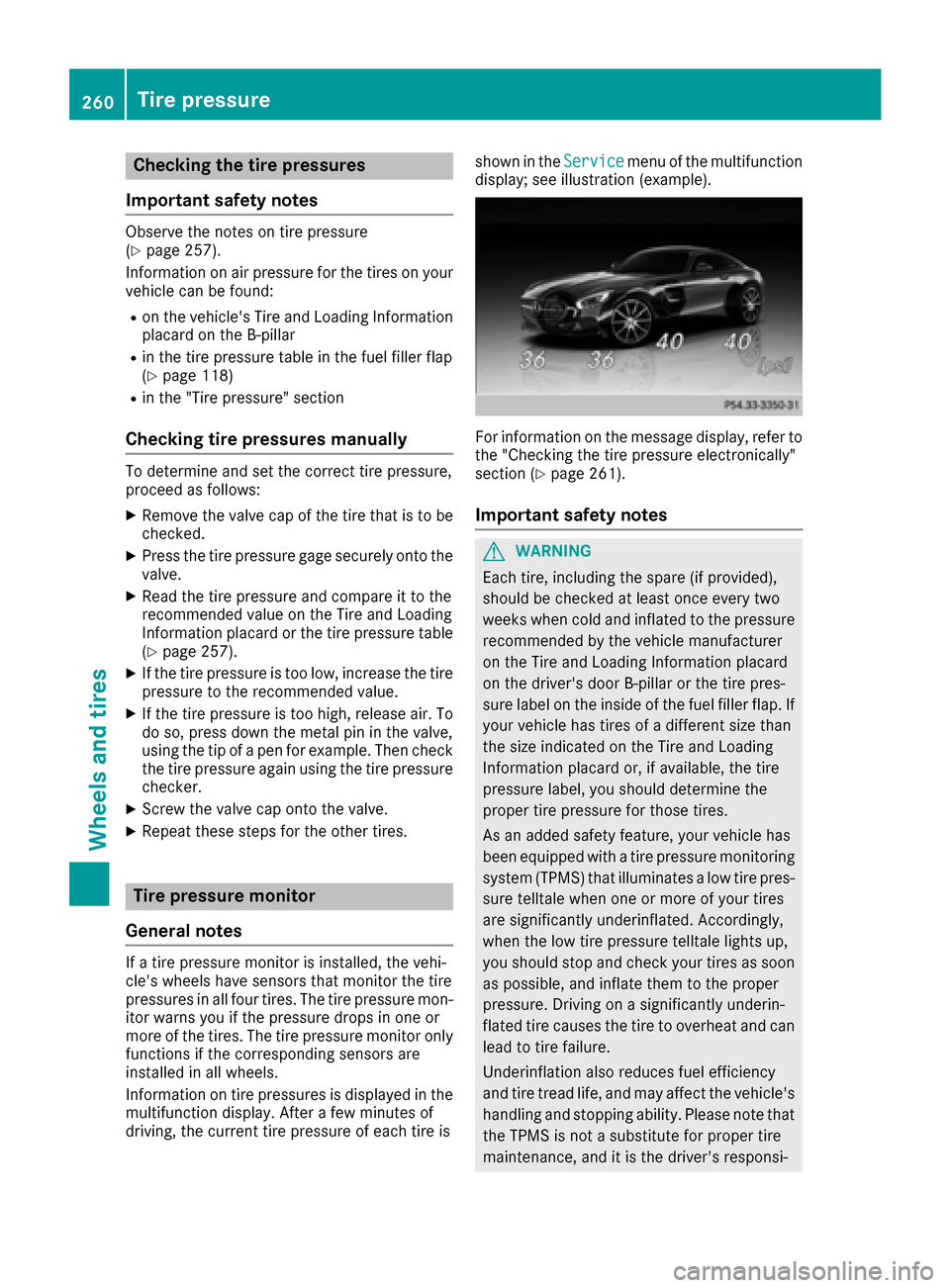
driving, the current tire pressure of each tire is shown in the
Service
menu of the multifunction
display; see illustration (example).
For information on the message display, refer to
the "Checking the tire pressure electronically"
section (
Ypage 261).
Important safety notes
GWARNING
Each tire, including the spare (if provided),
should be checked at least once every two
weeks when cold and inflated to the pressure recommended by the vehicle manufacturer
on the Tire and Loading Information placard
on the driver's door B-pillar or the tire pres-
sure label on the inside of the fuel filler flap. If
your vehicle has tires of a different size than
the size indicated on the Tire and Loading
Information placard or, if available, the tire
pressure label, you should determine the
proper tire pressure for those tires.
As an added safety feature, your vehicle has
been equipped with a tire pressure monitoring
system (TPMS) that illuminates a low tire pres-
sure telltale when one or more of your tires
are significantly underinflated. Accordingly,
when the low tire pressure telltale lights up,
you should stop and check your tires as soon
as possible, and inflate them to the proper
pressure. Driving on a significantly underin-
flated tire causes the tire to overheat and can
lead to tire failure.
Underinflation also reduces fuel efficiency
and tire tread life, and may affect the vehicle's
handling and stopping ability. Please note thatthe TPMS is not a substitute for proper tire
maintenance, and it is the driver's responsi-
260Tire pressure
Wheels and tires
Page 264 of 290
XPress9or: to select Tire Pres‐sure.
XPress the abutton.
The current tire pressure of each tire is shown
in the multifunction display.
If the vehicle was parked for longer than
20 minutes, the following message appears:
Tire
pressurewillbedisplayedafterdriving a few minutes.
After a teach-in process, the tire pressure mon-
itor automatically detects new wheels or new
sensors. As long as a clear allocation of the tire
pressure value to the individual wheels is not
possible, the Tire
PressureMonitorActivemessage is shown instead of the tire pressure
display. The tire pressures are already being
monitored.
Tire pressure monitor warning mes-
sages
If the tire pressure monitor detects a pressure
loss in one or more tires, a warning message is
shown in the multifunction display. The yellow
tire pressure warning lamp then lights up.
RIf thePlease Correct Tire Pressuremessage appears in the multifunction display,
the tire pressure in at least one tire is too low.
The tire pressure must be corrected when the opportunity arises.
RIf the Check Tiresmessage appears in the
multifunction display, the tire pressure in at
least one tire has dropped significantly. The
tires must be checked.
RIf the WarningTireMalfunctionmessage
appears in the multifunction display, the tire
pressure in at least one tire has dropped sud-
denly. The tires must be checked.
Observe the instructions and safety notes in the
display messages in the "Tires" section
(
Ypage 183).
If the wheel positions on the vehicle are rotated, the tire pressures may be displayed for the
wrong positions for a short time. This is rectified
after a few minutes of driving, and the tire pres-
sures are displayed for the correct positions.
Restarting the tire pressure monitor
When you restart the tire pressure monitor, all
existing warning messages are deleted and the
warning lamps go out. The monitor uses the cur-
rently set tire pressures as the reference values for monitoring. In most cases, the tire pressure
monitor will automatically detect the new refer-
ence values after you have changed the tire
pressure. However, you can also define refer-
ence values manually as described here. The tire
pressure monitor then monitors the new tire
pressure values.
XSet the tire pressure to the value recommen-
ded for the corresponding driving situation on
the Tire and Loading Information placard on
the driver's side B-pillar (
Ypage 257).
Additional tire pressures for various operating
conditions can be found in the tire pressure
table in the fuel filler flap (
Ypage 257).
XMake sure that the tire pressure is correct on
all four wheels.
XSwitch on the ignition (Ypage 103).
XUse ò on the steering wheel to call up the
list of menus.
XPress 9or: on the steering wheel to
select the Servicemenu.
XPress theabutton.
XPress 9or: to select Tire Pres‐sure.
XPress the abutton.
The current tire pressure for each wheel or
the Tire pressure will be displayed
after driving a few minutesmessage
will be displayed in the multifunction display.
XPress the :button.
The UseCurrentPressuresasNewRef‐erenceValuesmessage appears in the mul-
tifunction display.
If you wish to confirm the restart:
XPress the abutton.
The TirePress.MonitorRestartedmes-
sage appears in the multifunction display.
After driving for a few minutes, the system
checks whether the current tire pressures are
within the specified range. The new tire pres-
sures are then accepted as reference values
and monitored.
If you wish to cancel the restart:
XPress the %button.
The tire pressure values stored at the last
restart will continue to be monitored.
262Tire pressure
Wheels and tires
Page 274 of 290
PSI (pounds per square inch)
A standard unit of measure for tire pressure.
Aspect ratio
Relationship between tire height and tire width
in percent.
Tire pressure
This is pressure inside the tire applying an out-
ward force to each square inch of the tire's sur-
face. The tire pressure is specified in pounds per
square inch (psi), in kilopascal (kPa) or in bar.
The tire pressure should only be corrected when
the tires are cold.
Cold tire pressure
The tires are cold:
Rif the vehicle has been parked with the tires
out of direct sunlight for at least three hours
and
Rif the vehicle has not been driven further than
1 mile (1.6 km)
Tread
The part of the tire that comes into contact with
the road.
Bead
The tire bead ensures that the tire sits securely
on the wheel. There are several steel wires in the
bead to prevent the tire from coming loose fromthe wheel rim.
Sidewall
The part of the tire between the tread and the
bead.
Weight of optional extras
The combined weight of those optional extras
that weigh more than the replaced standard
parts and more than 5 lbs (2.3 kg). These
optional extras, such as high-performance
brakes, level control, a roof rack or a high-per-
formance battery, are not included in the curb
weight and the weight of the accessories.
TIN (Tire Identification Number)
This is a unique identifier which can be used by
a tire manufacturer to identify tires, for example
for a product recall, and thus identify the pur-
chasers. The TIN is made up of the manufactur-
er's identity code, tire size, tire type code and
the manufacturing date.
Load bearing index
The load bearing index (also load index) is a code
that contains the maximum load bearing capa-
city of a tire.
Traction
Traction is the result of friction between the tires
and the road surface.
Treadwear indicators
Narrow bars (tread wear bars) that are distrib-
uted over the tire tread. If the tire tread is level
with the bars, the wear limit of áin (1.6 mm)
has been reached.
Occupant distribution
The distribution of occupants in a vehicle at their
designated seating positions.
Total load limit
Nominal load and luggage load plus 68 kg
(150 lbs) multiplied by the number of seats in
the vehicle.
Changing a wheel
Flat tire
The "Breakdown assistance" section
(Ypage 242) contains information and notes on
how to deal with a flat tire.
Rotating the wheels
GWARNING
Interchanging the front and rear wheels may
severely impair the driving characteristics if
the wheels or tires have different dimensions. The wheel brakes or suspension components
may also be damaged. There is a risk of acci-
dent.
Rotate front and rear wheels only if the wheels and tires are of the same dimensions.
!On vehicles equipped with a tire pressure
monitor, electronic components are located
in the wheel.
Tire-mounting tools should not be used near
the valve. This could damage the electronic
components.
272Changing a wheel
Wheels and tires
Page 275 of 290
Only have tires changed at a qualified spe-
cialist workshop.
Always observe the instructions and safety
notes in the "Mounting a wheel" section
(
Ypage 273).
The wear patterns on the front and rear tires
differ, depending on the operating conditions.
Rotate the wheels before a clear wear pattern
has formed on the tires. Front tires typically
wear more on the shoulders and the rear tires in the center.
On vehicles that have the same size front and
rear wheels, you can rotate the wheels accord-
ing to the intervals in the tire manufacturer's
warranty book in your vehicle documents. If no
warranty book is available, the tires should be
rotated every 3,000 to 6,000 miles (5,000 to
10,000 km). Depending on tire wear, this may
be required earlier. Do not change the direction
of wheel rotation.
Clean the contact surfaces of the wheel and the
brake disc thoroughly every time a wheel is rota-
ted. Check the tire pressure and reactivate the
tire pressure monitor if necessary.
Direction of rotation
Tires with a specified direction of rotation have
additional benefits, e.g. if there is a risk of hydro-
planing. These advantages can only be gained if
the tires are installed corresponding to the
direction of rotation.
An arrow on the sidewall of the tire indicates its
correct direction of rotation.
Storing wheels
Store wheels that are not being used in a cool,
dry and preferably dark place. Protect the tires
from oil, grease, gasoline and diesel.
Mounting a wheel
Preparing the vehicle
XStop the vehicle on solid, non-slippery and
level ground.
XApply the electric parking brake manually.
XBring the front wheels into the straight-ahead position.
XShift the transmission to position P.
XSwitch off the engine.
XWith KEYLESS-GO start function or vehi-
cles with KEYLESS-GO:open the driver's
door.
The on-board electronics now have status 0.
This is the same as the SmartKey having been
removed.
or
XRemove the SmartKey from the ignition lock.
XIf included in the vehicle equipment, remove
the tire-change tool kit from the vehicle.
XSafeguard the vehicle against rolling away.
Securing the vehicle to prevent it from
rolling away
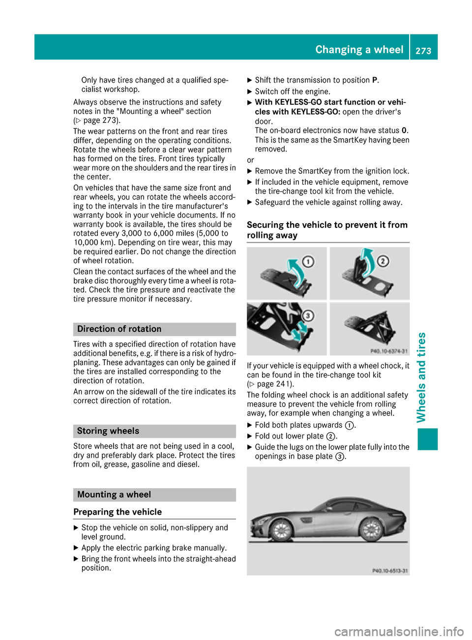
If your vehicle is equipped with a wheel chock, it
can be found in the tire-change tool kit
(
Ypage 241).
The folding wheel chock is an additional safety
measure to prevent the vehicle from rolling
away, for example when changing a wheel.
XFold both plates upwards :.
XFold out lower plate;.
XGuide the lugs on the lower plate fully into the
openings in base plate =.
Changing a wheel273
Wheels and tires
Z
Page 276 of 290
XPlace chocks or other suitable items under
the front and rear of the wheel that is diago-
nally opposite the wheel you wish to change.
Raising the vehicle
GWARNING
If you do not position the jack correctly at the
appropriate jacking point of the vehicle, the
jack could tip over with the vehicle raised.
There is a risk of injury.
Only position the jack at the appropriate jack-
ing point of the vehicle. The base of the jack
must be positioned vertically, directly under
the jacking point of the vehicle.
!The jack is designed exclusively for jacking
up the vehicle at the jacking points. Other-
wise, your vehicle could be damaged.
Observe the following when raising the vehi-
cle:
RTo raise the vehicle, only use the vehicle-spe-
cific jack that has been tested and approved
by Mercedes-Benz. If used incorrectly, the
jack could tip over with the vehicle raised.
RThe jack is designed only to raise and hold the
vehicle for a short time while a wheel is being
changed. It must not be used for performing
maintenance work under the vehicle.
RAvoid changing the wheel on uphill and down-
hill slopes.
RBefore raising the vehicle, secure it from roll-
ing away by applying the parking brake and
inserting wheel chocks. Do not disengage the
parking brake while the vehicle is raised.
RThe jack must be placed on a firm, flat and
non-slip surface. On a loose surface, a large,
flat, load-bearing underlay must be used. On a
slippery surface, a non-slip underlay must be
used, e.g. rubber mats.
RDo not use wooden blocks or similar objects
as a jack underlay. Otherwise, the jack will not be able to achieve its load-bearing capacity
due to the restricted height.
RMake sure that the distance between the
underside of the tires and the ground does not
exceed 1.2 in (3 cm).
RNever place your hands and feet under the
raised vehicle.
RDo not lie under the vehicle.
RDo not start the engine when the vehicle is
raised.
RNever open or close a door or the tailgate
when the vehicle is raised.
RMake sure that no persons are present in the
vehicle when the vehicle is raised.
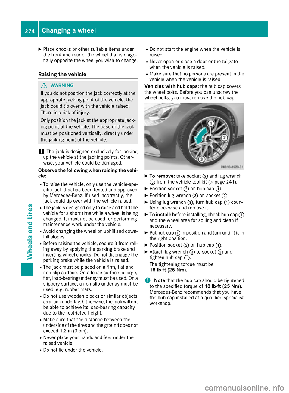
Vehicles with hub caps: the hub cap covers
the wheel bolts. Before you can unscrew the
wheel bolts, you must remove the hub cap.
XTo remove: take socket;and lug wrench
= from the vehicle tool kit (Ypage 241).
XPosition socket ;on hub cap :.
XPosition lug wrench =on socket ;.
XUsing lug wrench =, turn hub cap:coun-
ter-clockwise and remove it.
XTo install: before installing, check hub cap :
and the wheel area for soiling and clean if
necessary.
XPut hub cap :in position and turn until it is in
the right position.
XPosition socket ;on hub cap :.
XAttach lug wrench =to socket ;and
tighten hub cap :.
The tightening torque must be
18 lb-ft (25 Nm).
iNote that the hub cap should be tightened
to the specified torque of 18 lb-ft (25 Nm).
Mercedes-Benz recommends that you have
the hub cap installed at a qualified specialist
workshop.
274Changing a wheel
Wheels and tires