display MERCEDES-BENZ B-Class 2017 W246 Service Manual
[x] Cancel search | Manufacturer: MERCEDES-BENZ, Model Year: 2017, Model line: B-Class, Model: MERCEDES-BENZ B-Class 2017 W246Pages: 290, PDF Size: 19.81 MB
Page 125 of 290
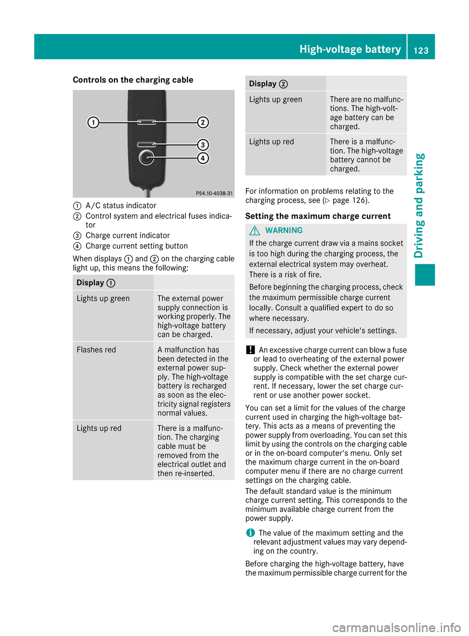
Controls on the charging cable
0043
A/C status indicator
0044 Control system and electrical fuses indica-
tor
0087 Charge current indicator
0085 Charge current setting button
When displays 0043and 0044on the charging cable
light up, this means the following: Display
0043 0043 Lights up green The external power
supply connection is
working properly. The
high-voltage battery
can be charged. Flashes red A malfunction has
been detected in the
external power sup-
ply. The high-voltage
battery is recharged
as soon as the elec-
tricity signal registers
normal values. Lights up red There is a malfunc-
tion. The charging
cable must be
removed from the
electrical outlet and
then re-inserted. Display
0044
0044 Lights up green There are no malfunc-
tions. The high-volt-
age battery can be
charged. Lights up red There is a malfunc-
tion. The high-voltage
battery cannot be
charged. For information on problems relating to the
charging process, see (Y
page 126).
Setting the maximum charge current G
WARNING
If the charge current draw via a mains socket is too high during the charging process, the
external electrical system may overheat.
There is a risk of fire.
Before beginning the charging process, check the maximum permissible charge current
locally. Consult a qualified expert to do so
where necessary.
If necessary, adjust your vehicle's settings.
! An excessive charge current can blow a fuse
or lead to overheating of the external power
supply. Check whether the external power
supply is compatible with the set charge cur-
rent. If necessary, lower the set charge cur-
rent or use another power socket.
You can set a limit for the values of the charge
current used in charging the high-voltage bat-
tery. This acts as a means of preventing the
power supply from overloading. You can set this limit by using the controls on the charging cable
or in the on-board computer's menu. Only set
the maximum charge current in the on-board
computer menu if there are no charge current
settings on the charging cable.
The default standard value is the minimum
charge current setting. This corresponds to the
minimum available charge current from the
power supply.
i The value of the maximum setting and the
relevant adjustment values may vary depend-
ing on the country.
Before charging the high-voltage battery, have
the maximum permissible charge current for the High-voltage battery
123Driving and parking Z
Page 126 of 290
relevant power socket checked by an electri-
cian.
X To adjust the setting: press button0085
repeatedly until the desired setting is selec-
ted in display 0087.
R Two LEDs are flashing: minimum setting
R All LEDs are flashing: maximum setting
Information about the charging time
(Y page 286)
If, after the charging process, the charging cable
is:
R left connected to the mains socket, the set
value will be used for the next charging proc-
ess.
R removed from the power socket, the values
will be reset to the minimum setting for the
next charging process. You may then need to
reset the values of the maximum charge cur-
rent.
If the charge current values that have been set
on the charging cable and the on-board com-
puter are different, the high-voltage battery is
charged using the lower value.
If the vehicle requires more time than usual to
charge the high-voltage battery, check:
R the settings of the maximum charge current
on the controls of the charging cable
R the settings of the maximum charge current in
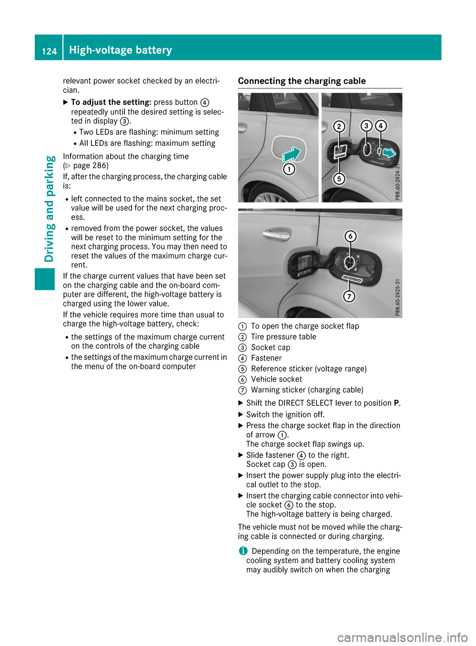
the menu of the on-board computer Connecting the charging cable 0043
To open the charge socket flap
0044 Tire pressure table
0087 Socket cap
0085 Fastener
0083 Reference sticker (voltage range)
0084 Vehicle socket
006B Warning sticker (charging cable)
X Shift the DIRECT SELECT lever to position P.
X Switch the ignition off.
X Press the charge socket flap in the direction
of arrow 0043.
The charge socket flap swings up.
X Slide fastener 0085to the right.
Socket cap 0087is open.
X Insert the power supply plug into the electri-
cal outlet to the stop.
X Insert the charging cable connector into vehi-
cle socket 0084to the stop.
The high-voltage battery is being charged.
The vehicle must not be moved while the charg-
ing cable is connected or during charging.
i Depending on the temperature, the engine
cooling system and battery cooling system
may audibly switch on when the charging 124
High-voltage batteryDriving and parking
Page 127 of 290
cable is connected or during the charging
process.
Removing the charging cable !
Before driving away, you must ensure that,
for your own safety and to avoid damage, the charging cable has been removed from the
vehicle socket. Otherwise, you cannot shift
the transmission out of position P.
When the charge level display reaches 100%,
the battery is fully charged (Y page 153).When the battery is charged:
X Press and hold button 006Con the charging
cable connector and remove the charging
cable from vehicle socket 0084.
X Close socket cap 0087.
X Close the charge socket flap.
X Remove the charging cable from the electrical
outlet.
X Stow the charging cable safely in the vehicle
(Y page 122). Charging high-voltage battery at a
charging station/wallbox
General notes Only use charging cables that have been tested
and approved by the manufacturer for charging
the high-voltage battery in an electric vehicle.
Pay attention to the "Important safety notes"
(Y page 117).
Charging communication at a charging
station The charging station first has to be activated
before you can charge at a charging station. You can activate the charging station by using an
RFID card or via telephone activation. Observe
the on-site operator instructions for the charg-
ing station.
When the vehicle is connected to the charging
station, information and details on technical
parameters are exchanged. It can thus take up
to 30 seconds for the charging process to begin.
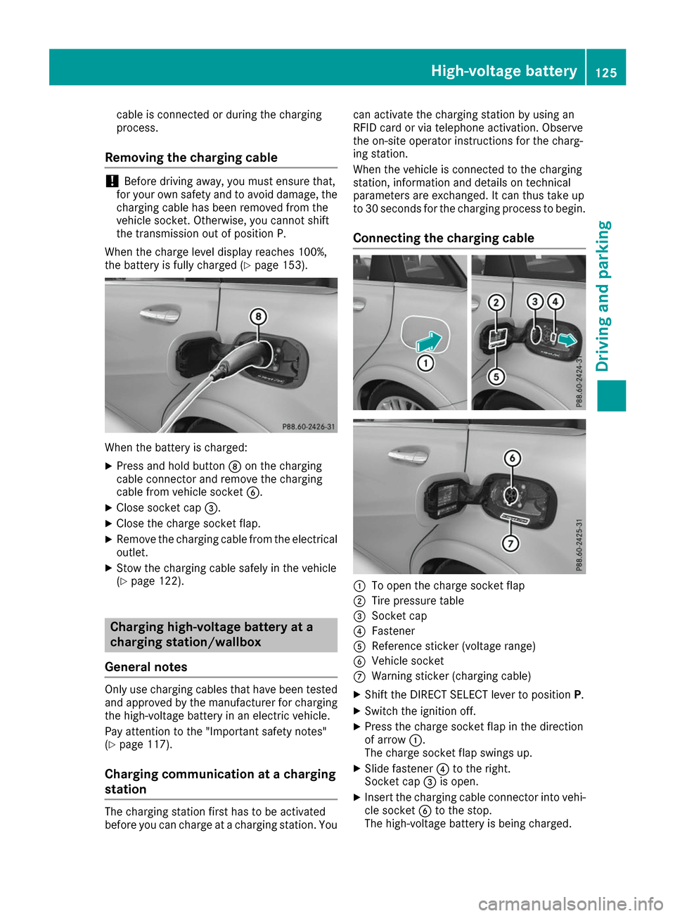
Connecting the charging cable 0043
To open the charge socket flap
0044 Tire pressure table
0087 Socket cap
0085 Fastener
0083 Reference sticker (voltage range)
0084 Vehicle socket
006B Warning sticker (charging cable)
X Shift the DIRECT SELECT lever to position P.
X Switch the ignition off.
X Press the charge socket flap in the direction
of arrow 0043.
The charge socket flap swings up.
X Slide fastener 0085to the right.
Socket cap 0087is open.
X Insert the charging cable connector into vehi-
cle socket 0084to the stop.
The high-voltage battery is being charged. High-voltage battery
125Driving and parking Z
Page 128 of 290
The vehicle must not be moved while the charg-
ing cable is connected or during charging.
i Depending on the temperature, the engine
cooling system and battery cooling system
may audibly switch on when the charging
cable is connected or during the charging
process.
Removing the charging cable !
Before driving away, you must ensure that,
for your own safety and to avoid damage, the
charging cable has been removed from the
vehicle socket. Otherwise, you cannot shift
the transmission out of position P.
When the charge level display reaches 100%,
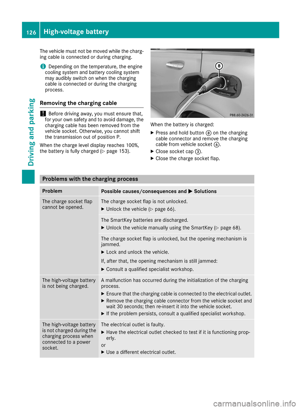
the battery is fully charged (Y page 153). When the battery is charged:
X Press and hold button 006Con the charging
cable connector and remove the charging
cable from vehicle socket 0084.
X Close socket cap 0087.
X Close the charge socket flap. Problems with the charging process
Problem
Possible causes/consequences and
0050 0050Solutions The charge socket flap
cannot be opened. The charge socket flap is not unlocked.
X Unlock the vehicle (Y page 66). The SmartKey batteries are discharged.
X Unlock the vehicle manually using the SmartKey (Y page 68).The charge socket flap is unlocked, but the opening mechanism is
jammed.
X Lock and unlock the vehicle.
If, after that, the opening mechanism is still jammed:
X Consult a qualified specialist workshop. The high-voltage battery
is not being charged. A malfunction has occurred during the initialization of the charging
process.
X Ensure that the charging cable is connected to the electrical outlet.
X Remove the charging cable connector from the vehicle socket and
wait 30 seconds; then re-insert it into the vehicle socket.
X If the problem persists, consult a qualified specialist workshop. The high-voltage battery
is not charged during the
charging process when
connected to a power
socket. The electrical outlet is faulty.
X Have the electrical outlet checked to test if it is functioning prop-
erly.
or X Use a different electrical outlet. 126
High-voltage batteryDriving and parking
Page 134 of 290
Drive sensibly – save energy
Observe the following tips to save energy:
R The tires should always be inflated to the rec-
ommended tire pressure.
R Remove unnecessary loads.
R Remove roof racks when they are not needed.
R Avoid frequent acceleration or braking.
Energy consumption also increases when driv-
ing in low or high outside temperatures, in stop-
start traffic, on short journeys and in hilly ter-
rain.
Drinking and driving G
WARNING
Drinking and driving and/or taking drugs and driving are very dangerous combinations.
Even a small amount of alcohol or drugs can
affect your reflexes, perceptions and judg-
ment.
The possibility of a serious or even fatal acci-
dent is greatly increased when you drink or
take drugs and drive.
Do not drink or take drugs and drive or allow
anyone to drive who has been drinking or tak-
ing drugs. ECO display
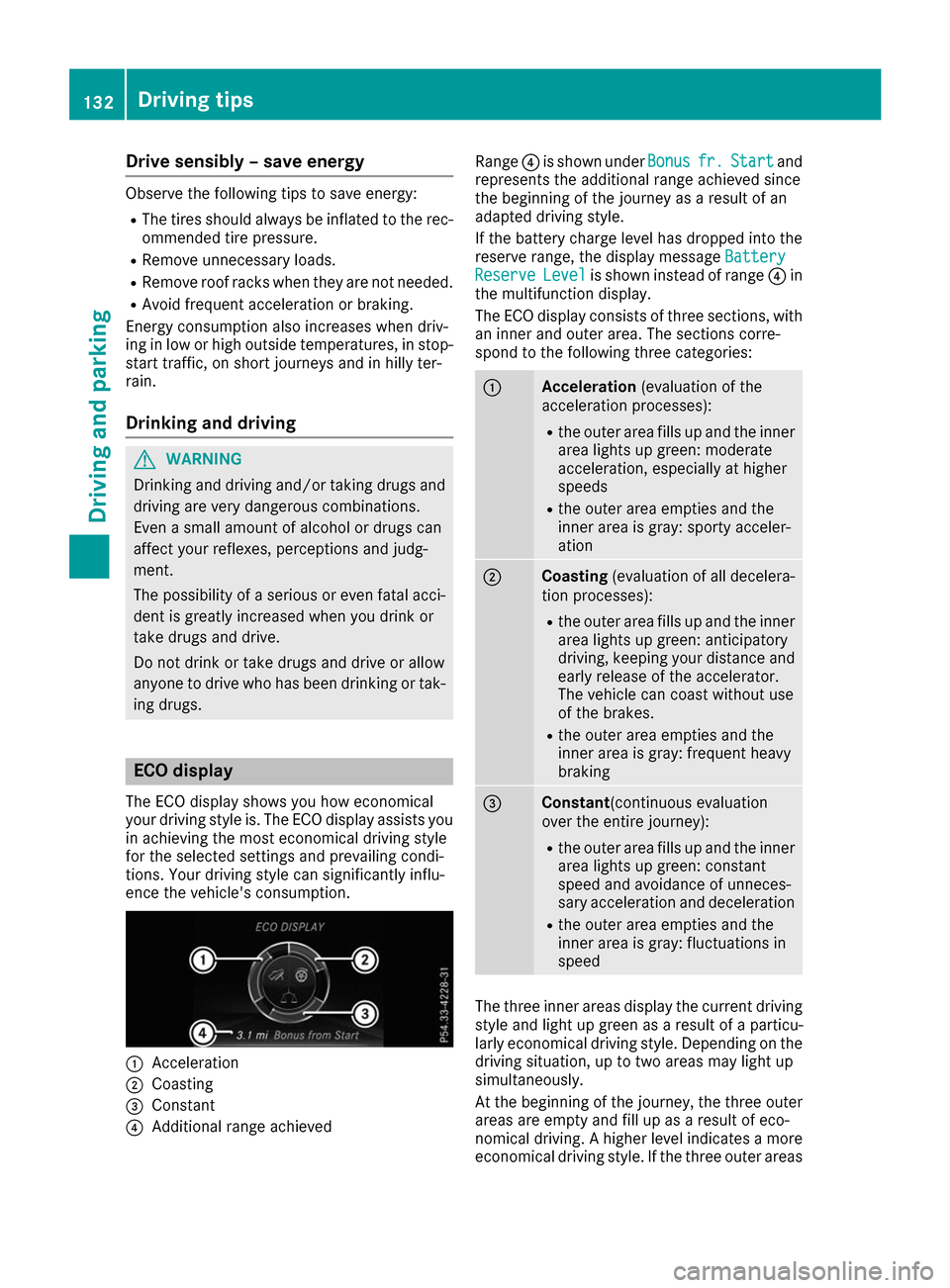
The ECO display shows you how economical
your driving style is. The ECO display assists you in achieving the most economical driving style
for the selected settings and prevailing condi-
tions. Your driving style can significantly influ-
ence the vehicle's consumption. 0043
Acceleration
0044 Coasting
0087 Constant
0085 Additional range achieved Range
0085is shown under Bonus Bonusfr. fr.Start
Start and
represents the additional range achieved since
the beginning of the journey as a result of an
adapted driving style.
If the battery charge level has dropped into the
reserve range, the display message Battery Battery
Reserve
Reserve Level
Levelis shown instead of range 0085in
the multifunction display.
The ECO display consists of three sections, with an inner and outer area. The sections corre-
spond to the following three categories: 0043
Acceleration
(evaluation of the
acceleration processes):
R the outer area fills up and the inner
area lights up green: moderate
acceleration, especially at higher
speeds
R the outer area empties and the
inner area is gray: sporty acceler-
ation 0044
Coasting
(evaluation of all decelera-
tion processes):
R the outer area fills up and the inner
area lights up green: anticipatory
driving, keeping your distance and
early release of the accelerator.
The vehicle can coast without use
of the brakes.
R the outer area empties and the
inner area is gray: frequent heavy
braking 0087
Constant
(continuous evaluation
over the entire journey):
R the outer area fills up and the inner
area lights up green: constant
speed and avoidance of unneces-
sary acceleration and deceleration
R the outer area empties and the
inner area is gray: fluctuations in
speed The three inner areas display the current driving
style and light up green as a result of a particu-
larly economical driving style. Depending on the driving situation, up to two areas may light up
simultaneously.
At the beginning of the journey, the three outer
areas are empty and fill up as a result of eco-
nomical driving. A higher level indicates a more
economical driving style. If the three outer areas 132
Driving tipsDriving and pa
rking
Page 135 of 290
are completely filled at the same time, the driver
has adopted the most economical driving style
for the selected settings and prevailing condi-
tions. The ECO display border lights up.
The ECO display does not indicate the actual fuel
consumption. The additionally achieved range
displayed under Bonus fr. Start
Bonus fr. Start does not
indicate a fixed consumption reduction.
In addition to driving style, the actual consump- tion is affected by other factors, such as:
R Load
R Tire pressure
R Cold start
R Choice of route
R Active electrical consumers
These factors are not included in the ECO dis-
play.
An economical driving style specially requires
driving at moderate engine speeds.
To achieve a higher value in the categories
"Acceleration" and "Constant", drive the vehicle
in drive program E+orE.
On long journeys at a constant speed, e.g. on the highway, only the outer area for "constant" will
change.
The ECO display summarizes the driving style
from the start of the journey to its completion.
Therefore, there are more marked changes in
the outer areas at the start of a journey. On lon-
ger journeys, there are fewer changes. For more
marked changes, perform a manual rest
(Y page 158).
For more information on the ECO display, see
(Y page 156). Braking
Important safety notes G
WARNING
If you increase the recuperation level on slip- pery road surfaces, the drive wheels may lose
their traction. There is an increased danger of skidding and accidents.
Do not increase the recuperation level on slip-
pery road surfaces. The braking performance of the electric motor
using recuperative braking is, in some operating
modes, either reduced or not effective:
R when the condition of charge of the high-volt-
age battery increases
R if the high-voltage battery is not yet at a nor-
mal operating temperature
R when driving close to the maximum speed
R when the vehicle is almost stationary
R in transmission position N
R during and after ESP stability control
If you do not make an additional effort to apply
the brake yourself, the braking effect may not be
sufficient. If necessary, counteract the reduced regenerative braking effect by applying the
brake yourself.
Downhill gradients On long, steep gradients, you must reduce the
load on the brakes by selecting maximum recu-
peration. This helps you to avoid overheating the
brakes and wearing them out excessively.
Recuperation allows the vehicle to be deceler-
ated without placing a load on the braking sys-
tem.
Do not depress the brake pedal continuously
while the vehicle is in motion, e.g. causing the
brakes to rub by constantly applying light pres-
sure to the pedal. This results in excessive and
premature wear to the brake pads.
Heavy and light loads G
WARNING
If you rest your foot on the brake pedal while
driving, the braking system can overheat. This increases the stopping distance and can even
cause the braking system to fail. There is a
risk of an accident.
Never use the brake pedal as a footrest. Never
depress the brake pedal and the accelerator
pedal at the same time.
! Depressing the brake pedal constantly
results in excessive and premature wear to
the brake pads.
If the brakes have been subjected to a heavy
load, do not stop the vehicle immediately. Drive on for a short while. This allows the airflow to
cool the brakes more quickly. Driving tips
133Driving and parking Z
Page 136 of 290
Wet roads
If you have driven for a long time in heavy rain
without braking, there may be a delayed reac-
tion from the brakes when braking for the first
time. This may also occur after the vehicle has
been washed or driven through deep water.
You have to depress the brake pedal more
firmly. Maintain a greater distance from the
vehicle in front.
After driving on a wet road or having the vehicle
washed, brake firmly while paying attention to
the traffic conditions. This will warm up the
brake discs, thereby drying them more quickly
and protecting them against corrosion.
Limited braking performance on salt-
treated roads If you drive on salted roads, a layer of salt resi-
due may form on the brake discs and brake
pads. This can result in a significantly longer
braking distance.
R In order to prevent any salt build-up, apply the
brakes occasionally while paying attention to
the traffic conditions.
R Carefully depress the brake pedal and the
beginning and end of a journey.
R Maintain a greater distance to the vehicle
ahead.
Servicing the brakes !
The brake fluid level may be too low, if:
R if the red brake warning lamp lights up in
the instrument cluster and
R you hear a warning tone while the engine is
running
Observe additional warning messages in the
multifunction display.
The brake fluid level may be too low due to
brake pad wear or leaking brake lines.
Have the brake system checked immediately.
Consult a qualified specialist workshop to
arrange this.
! A function or performance test should only
be carried out on a 2-axle dynamometer. If
you wish to operate the vehicle on such a
dynamometer, please consult a qualified spe- cialist workshop in advance. You could oth-
erwise damage the drive train or the brake
system. !
As the ESP ®
system operates automatically,
the engine and the ignition must be switched
off (the SmartKey must be in position 0or 1in
the ignition lock) if:
R the electric parking brake is tested on a
brake dynamometer (for a maximum of
ten seconds)
R the vehicle is towed with the front axle
raised.
Braking triggered automatically by ESP ®
may
seriously damage the brake system.
All checks and maintenance work on the brake
system must be carried out at a qualified spe-
cialist workshop.
Have brake pads installed and brake fluid
replaced at a qualified specialist workshop.
If the brake system has only been subject to
moderate loads, you should test the functional- ity of your brakes at regular intervals.
You can find a description of Brake Assist (BAS)
on (Y page 59).
Mercedes-Benz recommends that you only have brake pads/linings installed on your vehicle
which have been approved for Mercedes-Benz
vehicles or which correspond to an equivalent
quality standard. Brake pads/linings which havenot been approved for Mercedes-Benz vehicles
or which are not of an equivalent quality could
affect your vehicle's operating safety.
Mercedes-Benz recommends that you only use
brake fluid that has been specially approved for
your vehicle by Mercedes-Benz, or which corre- sponds to an equivalent quality standard. Brakefluid which has not been approved for
Mercedes-Benz vehicles or which is not of an
equivalent quality could affect your vehicle's
operating safety.
Checking brake lining thickness You can measure the break pad/lining thick-
ness using a test gage. Color-coding (green or
red) on the test gage allows you to determine
whether the brake pad/lining thickness is still
sufficient. The test gage is in the vehicle docu-
ment wallet in the glove box. 134
Driving tipsDriving and parking
Page 138 of 290
their traction. There is an increased danger of
skidding and accidents.
Do not increase the recuperation level on slip- pery road surfaces.
Have your vehicle winter-proofed at a qualified
specialist workshop at the onset of winter.
Drive particularly carefully on slippery road sur- faces. Avoid sudden acceleration, steering and
braking maneuvers. Do not use cruise control.
If the vehicle threatens to skid or cannot be
stopped when moving at low speed:
X Shift the DIRECT SELECT lever to position N.
The outside temperature indicator is not
designed to serve as an ice-warning device and is therefore unsuitable for that purpose.
Changes in the outside temperature are dis-
played after a short delay.
Indicated temperatures just above the freezing
point do not guarantee that the road surface is
free of ice. The road may still be icy, especially in
wooded areas or on bridges.
You should pay special attention to road condi-
tions when temperatures are around freezing
point.
For more information on driving with snow
chains, see (Y page 259).
For more information on driving with summer
tires, see (Y page 259).
Observe the notes in the "Winter operation" sec-
tion (Y page 259). Driving systems
Cruise control
General notes Cruise control maintains a constant road speed
for you. It brakes automatically in order to avoid
exceeding the set speed. Change into transmis-
sion position D-
(Y page 115) on long and steep
downhill gradients. This increases recuperation
in overrun mode. This relieves the load on the
brake system and prevents the brakes from
overheating and wearing too quickly.
When the engine is running, you can use the
cruise control lever to limit the speed to any
speed between 20 mph (30 km/h) and the tech-
nically permitted maximum speed of the vehicle. Use cruise control only if road and traffic con-
ditions make it appropriate to maintain a steady
speed for a prolonged period.
The speed indicated in the speedometer may
differ slightly from the speed stored.
Important safety notes If you fail to adapt your driving style, cruise con-
trol can neither reduce the risk of an accident
nor override the laws of physics. Cruise control
cannot take into account the road, traffic and
weather conditions. Cruise control is only an
aid. You are responsible for the distance to the
vehicle in front, for vehicle speed, for braking in
good time and for staying in your lane.
Do not use cruise control:
R in road and traffic conditions which do not
allow you to maintain a constant speed e.g. in
heavy traffic or on winding roads
R on slippery road surfaces. Braking or accel-
erating could cause the drive wheels to lose
traction and the vehicle could then skid
R in poor visibility, e.g. due to fog, heavy rain or
snow
If there is a change of drivers, advise the new
driver of the speed stored.
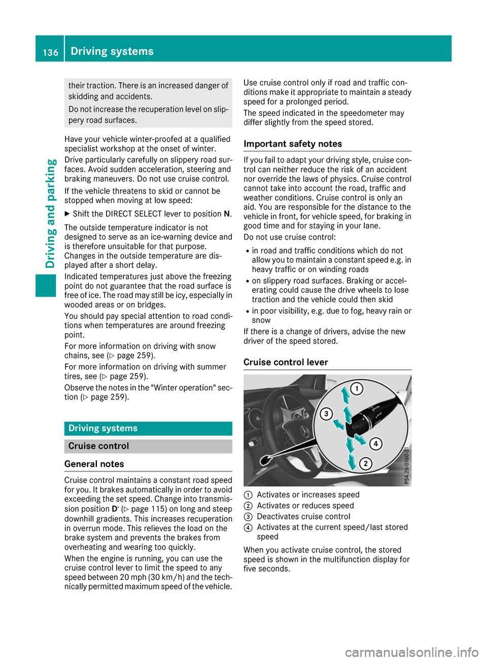
Cruise control lever 0043
Activates or increases speed
0044 Activates or reduces speed
0087 Deactivates cruise control
0085 Activates at the current speed/last stored
speed
When you activate cruise control, the stored
speed is shown in the multifunction display for
five seconds. 136
Driving systemsDriving an
d parking
Page 139 of 290
Activation conditions
To activate cruise control, all of the following
activation conditions must be fulfilled:
R the electric parking brake must be released.
R ESP ®
must be active, but not intervening.
R the transmission must be in position D.
Storing, maintaining and calling up a
speed Storing and maintaining the current
speed
You can store the current speed if you are driv-
ing faster than 20 mph (30 km/h).
X Accelerate the vehicle to the desired speed.
X Briefly press the cruise control lever up 0043or
down 0044.
X Remove your foot from the accelerator pedal.
Cruise control is activated. The vehicle auto-
matically maintains the stored speed.
i Cruise control may be unable to maintain
the stored speed on uphill gradients. The
stored speed is resumed when the gradient
evens out. Cruise control maintains the
stored speed on downhill gradients by auto-
matically applying the brakes.
Storing the current speed or calling up the
last stored speed G
WARNING
If you call up the stored speed and it differs
from the current speed, the vehicle acceler-
ates or decelerates. If you do not know the
stored speed, the vehicle could accelerate or brake unexpectedly. There is a risk of an acci-
dent.
Pay attention to the road and traffic condi-
tions before calling up the stored speed. If you do not know the stored speed, store the
desired speed again.
X Briefly pull the cruise control lever towards
you 0085.
X Remove your foot from the accelerator pedal.
The first time cruise control is activated, it
stores the current speed or regulates the
speed of the vehicle to the previously stored
speed. Setting a speed Keep in mind that it may take a brief moment
until the vehicle has accelerated or braked to
the speed set.
X To adjust the set speed in10 km/hincre-
ments:briefly press cruise control lever
0043up
beyond the pressure point for a higher speed, or down 0044for a lower speed.
or X Keep the cruise control lever pressed beyond
the point of resistance until the desired speed is set. Press cruise control lever up 0043for a
higher speed or down 0044for a lower speed.
X To adjust the set speed in1 km/hincre-
ments:briefly press cruise control lever up
0043
to the pressure point for a higher speed or
down 0044for a lower speed.
or
X Keep the cruise control lever pressed to the
point of resistance until the desired speed is
set. Press cruise control lever up 0043for a
higher speed or down 0044for a lower speed.
i Cruise control is not deactivated if you
depress the accelerator pedal. For example, if
you accelerate briefly to overtake, cruise con-
trol adjusts the vehicle's speed to the last
speed stored after you have finished overtak-
ing.
Deactivating cruise control There are several ways to deactivate cruise con-
trol:
X Briefly press the cruise control lever forwards
0087.
or X Brake.
Cruise control is automatically deactivated if: R the vehicle is secured with the electric park-
ing brake
R you are driving at less than 20 mph (30 km/h)
R ESP ®
intervenes or you deactivate ESP ®
R you shift the transmission to position Nwhile
driving
If cruise control is deactivated, you will hear a
warning tone. You will see the Cruise Con‐
Cruise Con‐
trol Off trol Off message in the multifunction display
for approximately five seconds. Driving systems
137Driving and parking Z
Page 140 of 290
i
When you switch off the engine, the last
speed stored is cleared. HOLD function
General notes The HOLD function can assist the driver in the
following situations:
R when pulling away, especially on steep slopes
R when maneuvering on steep slopes
R when waiting in traffic
The vehicle is kept stationary without the driver
having to depress the brake pedal.
The braking effect is canceled and the HOLD
function deactivated when you depress the
accelerator pedal to pull away.
Important safety notes G
WARNING
When leaving the vehicle, it can still roll away despite being braked by the HOLD function if:
R there is a malfunction in the system or in
the voltage supply.
R the HOLD function has been deactivated by
pressing the accelerator pedal or the brake
pedal, e.g. by a vehicle occupant.
R the electrical system in the engine com-
partment, the battery or the fuses have
been tampered with.
R the battery is disconnected
There is a risk of an accident.
If you wish to exit the vehicle, always turn off the HOLD function and secure the vehicle
against rolling away.
! If the HOLD function is activated, the vehicle
brakes automatically in certain situations.
To prevent damage to the vehicle, deactivate
the HOLD function in the following or other
similar situations:
R when towing the vehicle
R in the car wash
Deactivating the HOLD function (Y page 138).Activation conditions You can activate the HOLD function if:
R the vehicle is stationary
R the engine is running or if it has been auto-
matically switched off by the ECO start/stop
function
R the driver's door is closed or your seat belt is
fastened
R the electric parking brake is released
R the transmission position D,Ror Nis engaged
Activating the HOLD function X
Make sure that the activation conditions are
met.
X Depress the brake pedal.
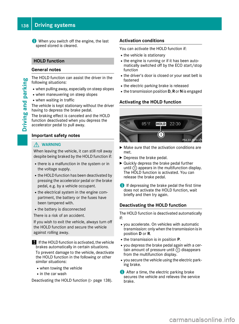
X Quickly depress the brake pedal further
until 0043appears in the multifunction display.
The HOLD function is activated. You can
release the brake pedal.
i If depressing the brake pedal the first time
does not activate the HOLD function, wait
briefly and then try again.
Deactivating the HOLD function The HOLD function is deactivated automatically
if:
R you accelerate. On vehicles with automatic
transmission: only when the transmission is in
position Dor R.
R the transmission is in position P.
R you depress the brake pedal again with a cer-
tain amount of pressure until 0043disappears
from the multifunction display.
R you secure the vehicle using the electric park-
ing brake.
i After a time, the electric parking brake
secures the vehicle and relieves the service
brake. 138
Driving systemsDriving and parking