battery MERCEDES-BENZ B-Class ELECTRIC 2016 W246 Manual PDF
[x] Cancel search | Manufacturer: MERCEDES-BENZ, Model Year: 2016, Model line: B-Class ELECTRIC, Model: MERCEDES-BENZ B-Class ELECTRIC 2016 W246Pages: 342, PDF Size: 7.53 MB
Page 294 of 342
Jump-starting
For the jump-starting procedure, use only the jump-starting connection point, consisting of a
positive terminal and a ground point, in the engine compartment.
GWARNING
Battery acid is caustic. There is a risk of injury.
Avoid contact with skin, eyes or clothing. Do not inhale any battery gases. Do not lean over the
battery. Keep children away from batteries. Wash away battery acid immediately with plenty of
clean water and seek medical attention.
GWARNING
During charging and jump-starting, explosive gases can escape from the battery. There is a risk of an explosion.
Particularly avoid fire, open flames, creating sparks and smoking. Ensure there is sufficient ven-
tilation while charging and jump-starting. Do not lean over a battery.
GWARNING
During the charging process, a battery produces hydrogen gas. If a short circuit occurs or sparks
are created, the hydrogen gas can ignite. There is a risk of an explosion.
RMake sure that the positive terminal of a connected battery does not come into contact with
vehicle parts.
RNever place metal objects or tools on a battery.
RIt is important that you observe the described order of the battery terminals when connecting
and disconnecting a battery.
RWhen jump-starting, make sure that the battery poles with identical polarity are connected.
RIt is particularly important to observe the described order when connecting and disconnecting
the jumper cables.
RNever connect or disconnect the battery terminals while the engine is running.
GWARNING
A discharged battery can freeze at temperatures below freezing point. When jump-starting the
vehicle or charging the battery, gases can escape from the battery. There is a risk of an explosion. Allow the frozen battery to thaw out before charging it or jump-starting.
!Avoid repeated and lengthy starting attempts.
Do not use a rapid-charging device to start the engine.
If the indicator/warning lamps do not light up at low temperatures, it is very likely that the
discharged battery has frozen. In this case you may neither jump-start the vehicle nor charge the battery. The service life of a thawed-out battery may be shorter. Have the thawed-out
battery checked at a qualified specialist workshop.
If the 12 V battery is discharged, or after the vehicle has been jump-started, the Service
RequiredDoNotShiftGearsVisitDealermessage appears. There is a malfunction in
the on-board voltage. Visit a qualified specialist workshop immediately.
292Jump-starting
Breakdown assistance
Page 295 of 342
The drive system cannot be started if the 12 V battery is discharged. This is not dependent on
whether the high-voltage battery is charged or not. The vehicle cannot be jump-started if the
high-voltage battery is discharged. The high-voltage battery must be charged first.
The drive system can be started using another vehicle.
ROnly use batteries with an equal nominal voltage (12 volts).
RMake sure that the battery of the donor vehicle does not have a significantly lower capacitythan the discharged battery.
RUse jumper cables with a sufficient cross-section and insulated terminal clamps from a
qualified specialist workshop, e.g. an authorized Mercedes-Benz Center.
RMake sure that the two vehicles do not touch.
RRoute the jumper cables so that they cannot be caught by rotating components in the engine
compartment.
RDo not disconnect the discharged battery from the vehicle's electrical system.
XSwitch off the engine of both vehicles.
XShift the transmission to position P.
XSwitch off all electrical consumers.
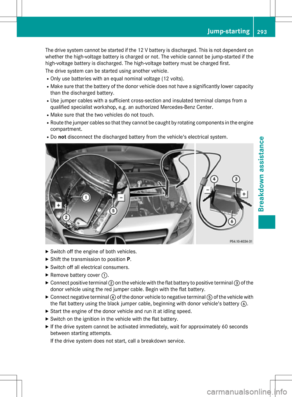
XRemove battery cover:.
XConnect positive terminal ;on the vehicle with the flat battery to positive terminal =of the
donor vehicle using the red jumper cable. Begin with the flat battery.
XConnect negative terminal ?of the donor vehicle to negative terminal Aof the vehicle with
the flat battery using the black jumper cable, beginning with donor vehicle's battery B.
XStart the engine of the donor vehicle and run it at idling speed.
XSwitch on the ignition in the vehicle with the flat battery.
XIf the drive system cannot be activated immediately, wait for approximately 60 seconds
between starting attempts.
If the drive system does not start, call a breakdown service.
Jump-starting293
Breakdown assistance
Z
Page 297 of 342
!When towing, pull away slowly and
smoothly. If the tractive power is too high,
the vehicles could be damaged.
!The vehicle can be towed a maximum of
30 miles (50km). The towing speed of
30 mph (50km/h) must not be exceeded.
If the vehicle has to be towed more than
30 miles (50km), the front axle must be
raised or the entire vehicle raised and
transported.
!Do not tow with sling-type equipment.
This could damage the vehicle.
!To tow vehicles with KEYLESS-GO, use
the SmartKey instead of the Start/Stop
button. The transmission may otherwise
shift to position Pwhen you open the driv-
er's or front-passenger door, which could
damage the transmission.
Observe the legal requirements for the rele-
vant countries when towing away.
Make sure that no charging cable is plugged
in. The parking lock cannot be released if a
charging cable is plugged in.
It is better to have the vehicle transported
than to have it towed away.
If the vehicle can no longer be driven because
of an accident or breakdown, you have the
following options:
RTransporting the vehicle
As a rule, you should have the vehicle trans-
ported.
RTowing the vehicle with a tow rope or tow
bar
Only tow the vehicle in exceptional cases.
Observe the following notes.
The vehicle may not be towed and must
always be transported if:
Rthe multifunction display is not working
Rone of more of the following warning lamps
is lit up:
-Drive system
-12 V battery
Rone or both of the following display mes-
sages have appeared:
-Stop Switch Engine off
-Do Not Shift Gears Visit Dealer
Ryou have to tow the vehicle over a longer
distance than 30 miles (50 km).
The battery must be connected and charged.
Otherwise, you:
Rcannot turn the SmartKey to position 2in
the ignition lock
Rcannot release the electric parking brake
Rcannot shift the transmission to position N
The function of the electric parking brake and
the parking lock is dependent on the on-board voltage.
If the on-board voltage is low or there is a
system malfunction, it is possible that:
Rthe electric parking brake may not be
applied in certain circumstances, or
Rthe transmission may not be shifted to P
Switch off non-essential consumers, e.g. the
radio.
Disarm the automatic locking feature before
the vehicle is towed (
Ypage 198). You could
otherwise be locked out when pushing or
towing the vehicle.
Towing295
Breakdown assistance
Z
Page 298 of 342

Installing/removing the towing eye
Installing the towing eye
The brackets for the screw-in towing eye are
located in the bumpers. They are at the rear
and at the front, under covers :.
XRemove the towing eye from the stowage
space.
The towing eye is located in the stowage
well under the cargo compartment floor.
Vehicles with the TIREFIT kit: the to wing
eye is beneath the tire inflation compres-
sor.
XPress the mark on cover :inwards in the
direction of the arrow.
XTake cover :off the opening.
XScrew in the towing eye clockwise to the
stop.
Removing the towing eye
XUnscrew and remove the towing eye.
XPlace the towing eye in the stowage well
beneath the cargo compartment floor in
the cargo compartment (
Ypage 282).
XVehicles with the TIREFIT kit: put back the
tire inflation compressor.
Towing a vehicle with both axles on
the ground
It is important that you observe the safety
instructions when towing away your vehicle
(
Ypage 294).
XOn vehicles with KEYLESS-GO or the
KEYLESS-GO start function: you must
use the SmartKey instead of the Start /S top
button (
Ypage 132).
The transmission automatically shifts to posi-
tion Pwhen you open the driver's or front-
passenger door or when you remove the
Sm artKey from the ignition lock. In order to
ensure that the transmission stays in position
N when towing the vehicle, you must observe
the following points:
XMake sure that the vehicle is stationary.
XTurn the SmartKey to position 2in the igni-
tion lock.
XDepress and hold the brake pedal.
XSh ift the transmission to position N.
XRelease the brake pedal.
XRelease the electric parking brake.
XSwitch on the hazard warning lamps
(
Ypage 102).
XLeave the SmartKey in position 2in the
ignition lock.
If the 12 V battery indicator lamp lights up,
you must observe the following points:
XPull over and stop the vehicle safely as soon
as possible, paying attention to road and
traff iccond itions.
XShift the transmission to position P.
XApply the electric parking brake.
iIn order to signal a change of direction
when towing the vehicle with the hazard
warning lamps switched on, use the com-
bination switch as usual. In this case, only
the indicator lamps for the direction of
travel flash. After resetting the combina-
tion switch, the hazard warning lamp starts
flashing again.
296Towing
Breakdown assistance
Page 324 of 342
Curb weight
The weight of a vehicle with standard equip-
ment including the maximum capacity of fuel,
oil and coolant. It also includes the air-condi-
tioning system and optional equipment if
these are installed in the vehicle, but does not
include passengers or luggage.
Maximum load rating
The maximum tire load is the maximum per-
missible weight in kilograms or lbs for which a
tire is approved.
Maximum permissible tire pressure
Maximum permissible tire pressure for one
tire.
Maximum load on one tire
Maximum load on one tire. This is calculated
by dividing the maximum axle load of one axle
by two.
PSI (pounds per square inch)
A standard unit of measure for tire pressure.
Aspect ratio
Relationship between tire height and tire
width in percent.
Tire pressure
This is pressure inside the tire applying an
outward force to each square inch of the tire's
surface. The tire pressure is specified in
pounds per square inch (psi), in kilopascal
(kPa) or in bar. The tire pressure should only
be corrected when the tires are cold.
Cold tire pressure
The tires are cold:
Rif the vehicle has been parked with the tires
out of direct sunlight for at least three
hours and
Rif the vehicle has not been driven further
than 1 mile (1.6 km) Tread
The part of the tire that comes into contact
with the road.
Bead
The tire bead ensures that the tire sits
securely on the wheel. There are several steel
wires in the bead to prevent the tire from
coming loose from the wheel rim.
Sidewall
The part of the tire between the tread and the
bead.
Weight of optional extras
The combined weight of those optional extras
that weigh more than the replaced standard
parts and more than 2.3 kg (5 lbs). These
optional extras, such as high-performance
brakes, level control, a roof rack or a high-
performance battery, are not included in the
curb weight and the weight of the accesso-
ries.
TIN (Tire Identification Number)
This is a unique identifier which can be used
by a tire manufacturer to identify tires, for
example for a product recall, and thus identify
the purchasers. The TIN is made up of the
manufacturer's identity code, tire size, tire
type code and the manufacturing date.
Load bearing index
The load bearing index (also load index) is a
code that contains the maximum load bearing
capacity of a tire.
Traction
Traction is the result of friction between the
tires and the road surface.
Treadwear indicators
Narrow bars (tread wear bars) that are dis-
tributed over the tire tread. If the tire tread is
level with the bars, the wear limit of áin
(1.6 mm) has been reached.
322All about wheels and tires
Wheels and tires
Page 326 of 342
XVehicles without KEYLESS-GO:remove
the SmartKey from the ignition lock.
XVehicles with KEYLESS-GO start-func-
tion or KEYLESS-GO: open the driver's
door.
The on-board electronics now have status
0 . This is the same as the SmartKey having
been removed.
XVehicles with KEYLESS-GO start-func-
tion or KEYLESS-GO: remove the Start/
Stop button from the ignition lock
(
Ypage 131).
XIf included in the vehicle equipment,
remove the tire-change tool kit from the
vehicle.
XSafeguard the vehicle against rolling away
(
Ypage 153).
Securing the vehicle to prevent it from
rolling away
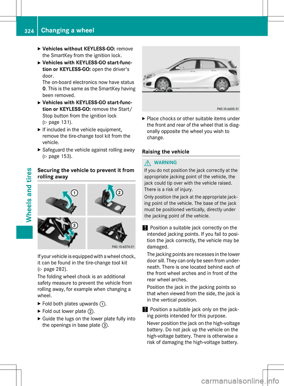
If your vehicle is equipped with a wheel chock,
it can be found in the tire-change tool kit
(
Ypage 282).
The folding wheel chock is an additional
safety measure to prevent the vehicle from
rolling away, for example when changing a
wheel.
XFold both plates upwards :.
XFold out lower plate;.
XGuide the lugs on the lower plate fully into
the openings in base plate =.
XPlace chocks or other suitable items under
the front and rear of the wheel that is diag-
onally opposite the wheel you wish to
change.
Raising the vehicle
GWARNING
If you do not position the jack correctly at the
appropriate jacking point of the vehicle, the
jack could tip over with the vehicle raised.
There is a risk of injury.
Only position the jack at the appropriate jack-
ing point of the vehicle. The base of the jack
must be positioned vertically, directly under
the jacking point of the vehicle.
!Position a suitable jack correctly on the
intended jacking points. If you fail to posi-
tion the jack correctly, the vehicle may be
damaged.
The jacking points are recesses in the lower
door sill. They can only be seen from under-
neath. There is one located behind each of
the front wheel arches and in front of the
rear wheel arches.
Position the jack in the jacking points so
that when viewed from the side, the jack is
in the vertical position.
!Position a suitable jack only on the jack-
ing points intended for this purpose.
Never position the jack on the high-voltage
battery. Do not jack up the vehicle on the
high-voltage battery. There is otherwise a
risk of damaging the high-voltage battery.
324Changing a wheel
Wheels and tires
Page 340 of 342
Vehicle data
General notes
Please note that for the specified vehicle
data:
Rthe heights specified may vary as a result
of:
-tires
-load
-condition of the suspension
-optional equipment
Roptional equipment reduces the maximum
payload.
The range depends on the drive program
selected and can vary due to:
Rhigher and lower outside temperatures
Rthe style of driving
Ractivated electrical consumers
iFurther information on the range can be
found in the Trip
menu (Ypage 188).
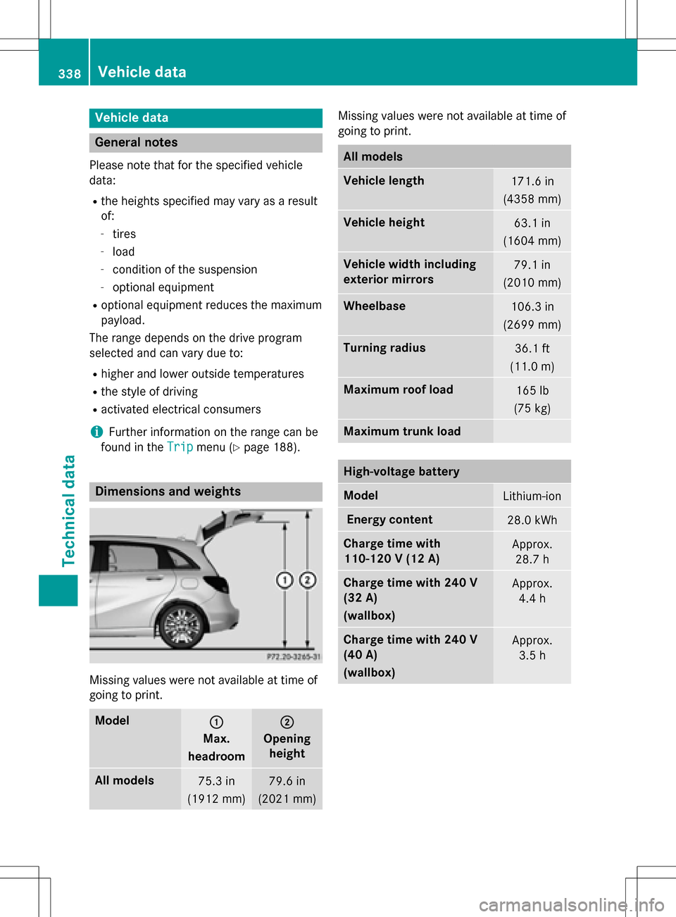
Dimensions and weights
Missing values were not available at time of
going to print.
Model:
Max.
headroom
;
Opening height
All models75.3 in
(1912 mm)79.6 in
(2021 mm)
Missing values were not available at time of
going to print.
All models
Vehicle length171.6 in
(4358 mm)
Vehicle height63.1 in
(1604 mm)
Vehicle width including
exterior mirrors79.1 in
(2010 mm)
Wheelbase106.3 in
(2699 mm)
Turning radius36.1 ft
(11.0 m)
Maximum roof load165 lb
(75 kg)
Maximum trunk load
High-voltage battery
ModelLithium-ion
Energy content28.0 kWh
Charge time with
110-120 V (12 A)Approx. 28.7 h
Charge time with 240 V
(32 A)
(wallbox)Approx. 4.4 h
Charge time with 240 V
(40 A)
(wallbox)Approx.3.5 h
338Vehicle data
Technical data