oil MERCEDES-BENZ B-Class ELECTRIC 2016 W246 Owner's Manual
[x] Cancel search | Manufacturer: MERCEDES-BENZ, Model Year: 2016, Model line: B-Class ELECTRIC, Model: MERCEDES-BENZ B-Class ELECTRIC 2016 W246Pages: 342, PDF Size: 7.53 MB
Page 74 of 342
Useful information
i
This Operator's Manual describes all
models and all standard and optional equip-
ment of your vehicle available at the time of
publication of the Operator's Manual.
Country-specific differences are possible.
Please note that your vehicle may not be
equipped with all features described. This
also applies to safety-related systems and
functions.
iRead the information on qualified special-
ist workshops (
Ypage 26).
SmartKey
Important safety notes
GWARNING
If children are left unsupervised in the vehicle,
they could:
Ropen the doors, thus endangering other
people or road users.
Rget out and disrupt traffic.
Roperate the vehicle's equipment.
Additionally, children could set the vehicle in
motion if, for example, they:
Rrelease the parking brake.
Rshift the transmission out of park position P
Rstart the vehicle's drive system.
There is a risk of an accident and injury.
When leaving the vehicle, always take the
SmartKey with you and lock the vehicle. Never
leave children or animals unattended in the
vehicle. Always keep the SmartKey out of
reach of children.
GWARNING
If you attach heavy or large objects to the
SmartKey, the SmartKey could be uninten-
tionally turned in the ignition lock. This could
cause the engine to be switched off. There is a risk of an accident.
Do not attach any heavy or large objects to theSmartKey. Remove any bulky key rings before
inserting the SmartKey into the ignition lock.
!Keep the SmartKey away from strong
magnetic fields. Otherwise, the remote
control function could be affected.
Strong magnetic fields can occur in the
vicinity of powerful electrical installations.
Do not keep the SmartKey:
Rwith electronic devices, e.g. a mobile
phone or another SmartKey.
Rwith metallic objects, e.g. coins or metal
foil.
Rinside metallic objects, e.g. a metal case.
Vehicles with KEYLESS-GO start function:
do not keep the SmartKey in the cargo com-
partment. Otherwise, the SmartKey may not
be detected, e.g. when starting the drive sys-
tem using the Start/Stop button.
SmartKey functions
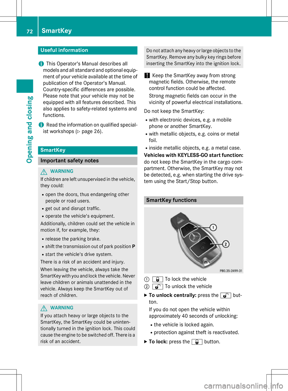
:& To lock the vehicle
;%To unlock the vehicle
XTo unlock centrally: press the%but-
ton.
If you do not open the vehicle within
approximately 40 seconds of unlocking:
Rthe vehicle is locked again.
Rprotection against theft is reactivated.
XTo lock: press the &button.
72SmartKey
Opening and closing
Page 133 of 342
Rin transmission positionN
Rduring and after ESP stability control
If you do not make an additional effort to
apply the brake yourself, the braking effect
may not be sufficient. If necessary, counter-
act the reduced regenerative braking effect
by applying the brake yourself.
Before commencing your journey, ensure that the charging cable required for charging the
high-voltage battery is in the vehicle.
SmartKey positions
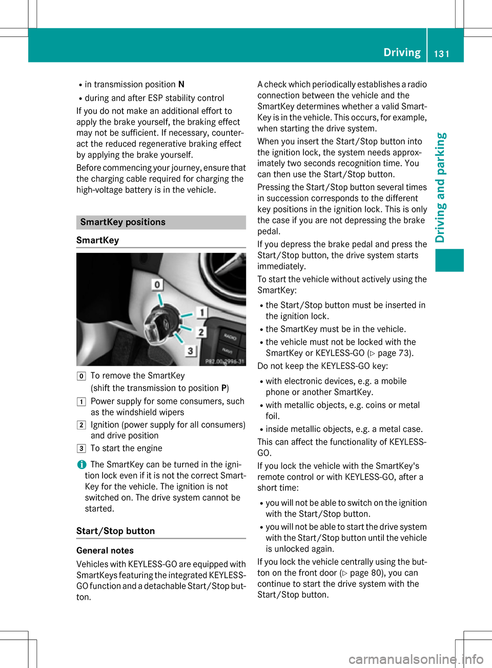
SmartKey
gTo remove the SmartKey
(shift the transmission to position P)
1Power supply for some consumers, such
as the windshield wipers
2Ignition (power supply for all consumers)
and drive position
3To start the engine
iThe SmartKey can be turned in the igni-
tion lock even if it is not the correct Smart- Key for the vehicle. The ignition is not
switched on. The drive system cannot be
started.
Start/Stop button
General notes
Vehicles with KEYLESS-GO are equipped with
SmartKeys featuring the integrated KEYLESS-GO function and a detachable Start/Stop but-
ton. A check which periodically establishes a radio
connection between the vehicle and the
SmartKey determines whether a valid Smart-
Key is in the vehicle. This occurs, for example,
when starting the drive system.
When you insert the Start/Stop button into
the ignition lock, the system needs approx-
imately two seconds recognition time. You
can then use the Start/Stop button.
Pressing the Start/Stop button several times
in succession corresponds to the different
key positions in the ignition lock. This is only
the case if you are not depressing the brake
pedal.
If you depress the brake pedal and press the
Start/Stop button, the drive system starts
immediately.
To start the vehicle without actively using the
SmartKey:
Rthe Start/Stop button must be inserted in
the ignition lock.
Rthe SmartKey must be in the vehicle.
Rthe vehicle must not be locked with the
SmartKey or KEYLESS-GO (
Ypage 73).
Do not keep the KEYLESS-GO key:
Rwith electronic devices, e.g. a mobile
phone or another SmartKey.
Rwith metallic objects, e.g. coins or metal
foil.
Rinside metallic objects, e.g. a metal case.
This can affect the functionality of KEYLESS-
GO.
If you lock the vehicle with the SmartKey's
remote control or with KEYLESS-GO, after a
short time:
Ryou will not be able to switch on the ignition
with the Start/Stop button.
Ryou will not be able to start the drive system
with the Start/Stop button until the vehicle is unlocked again.
If you lock the vehicle centrally using the but-
ton on the front door (
Ypage 80), you can
continue to start the drive system with the
Start/Stop button.
Driving131
Driving and parking
Z
Page 144 of 342
To ensure that the brackets within the charg-
ing cable controls are not subjected to incor-
rect loads, observe the following:
RNever lift or carry the controls by the charg-ing cable connector or the mains plug.
RTo transport the charging cable, the coiled
part can be:
-wrapped around the controls or
-secured to the housing of the controls
Heat generated by the charging cable
and charging cable connector
Pay attention to the important safety notes
(
Ypage 140).
During the charging process, the charging
cable and charging cable connector may heat
up.
The charging cable and charging cable con-
nector will only heat up within the permissible
limiting values, provided that:
Rthe power supply and the charging cable
are not damaged
Rthe instructions for handling the charging
cable and controls on the charging cable
are observed
Should the permissible heating temperature
limits be exceeded, have the mains power
supply checked.
Protection device against overvoltage
!Voltage surges in the mains supply can
damage the vehicle. The vehicle is there-
fore equipped with a device which protects
it from voltage surges in the mains supply.
This device may be triggered during severe
thunderstorms, for example, and may lead
to the building's fuse being tripped and an
interruption in the power supply. These
functions protect the vehicle. After the
building fuse is switched on again, the
charging process resumes automatically.
Following an interruption in the power sup- ply without tripping of the building's fuse, it may take up to 15 minutes for charging to
resume automatically.
Switch on the building's fuse again after the
protection device against overvoltage has
been triggered. Otherwise, the charging proc-
ess cannot be continued. The high-voltage
battery will not be charged and you may not
be able to drive the vehicle.
If other devices are protected by the same
protective device, these are switched off as
well when the protective device is triggered.
Ensure that these other devices are still
operational after reactivating the protection
device.
Influences on the charging behavior
and the charge state of the high-volt-
age battery
Terms of use
Observe the following notes:
Rinformation on exceptions and limitations
in warranty documentation and in the rela-
ted Maintenance Booklet
Rmaintenance notes for the high-voltage
battery in the Maintenance Booklet
Method of operation
The vehicle is equipped with a high-voltage
battery for driving. The high-voltage battery
stores the energy needed to operate the elec-
tric motor and releases it again.
The electric motor uses energy that has been
stored in the high-voltage battery when pull-
ing away, accelerating and during the jour-
ney.
In overrun mode (except D+), kinetic energy
is converted by means of energy recuperation
into electrical energy and stored in the high-
voltage battery.
142High-voltage battery
Driving and parking
Page 277 of 342
XRinse the vehicle with clean water and dry
thoroughly withachamois.
XDo not let the cleaning agent dry on the
paintwork.
Carefully remove all deposits of road salt as
soon as possible when driving in winter.
Power washers
GWARNING
The water jet froma circular jet nozzle (dirt
blasters) can cause invisible exterior damage
to th e tires or chassis components. Compo-
nent s damaged in this way may fail unexpect-
edly. There is a risk of an accident.
Do no t use power washers with circular jet
nozzles to clean th e vehicle. Have damaged
tires or chassis components replaced imme-
diately.
!Always maintainadistance of at least
11.8 in (30 cm)betwee n thevehicl e and the
power washer nozzle. Information about
the correct distance is available from the
equipment manufacturer.
Move the power washer nozzle around
when cleaning your vehicle.
Do not aim directly at any of the following:
Rtires
Rdoor gaps, roof gaps, joints, etc.
Relectrical components
Rbattery
Rconnectors
Rlights
Rseals
Rtrim
Rventilation slots
Damaged seals or electrical components
can lead to leaks or failures.
Cleaning the paintwork
!Do not affix:
Rstickers
Rfilms
Rmagnetic plates or similar items
to painted surfaces. You could otherwise
damage the paintwork.
Scratches, corrosive deposits, areas affected
by corrosion and damage caused by inade-
quate care cannot always be completely
repaired. In such cases, visit a qualified spe-
cialist workshop.
XRemove dirt immediately, where possible,
while avoiding rubbing too hard.
XSoak insect remains with insect remover
and rinse off the treated areas afterwards.
XSoak bird droppings with water and rinse
off the treated areas afterwards.
XRemove coolant, brake fluid, tree resin,
oils, fuels and greases by rubbing gently
with a cloth soaked in petroleum ether or
lighter fluid.
XUse tar remover to remove tar stains.
XUse silicone remover to remove wax.
If water no longer forms "beads" on the paint surface, use the paint care products recom-
mended and approved by Mercedes-Benz.
This is the case approximately every three to
five months, depending on the climate con-
ditions and the care product used.
If dirt has penetrated the paint surface or if
the paint has become dull, the paint cleaner
recommended and approved by Mercedes-
Benz should be used.
Do not use these care products in the sun or
on the hood while the hood is hot.
XUse a suitable touch-up stick, e.g. MB
Touch-Up Stick, to repair slight damage to
the paintwork quickly and provisionally.
Care275
Maintenance and care
Z
Page 280 of 342
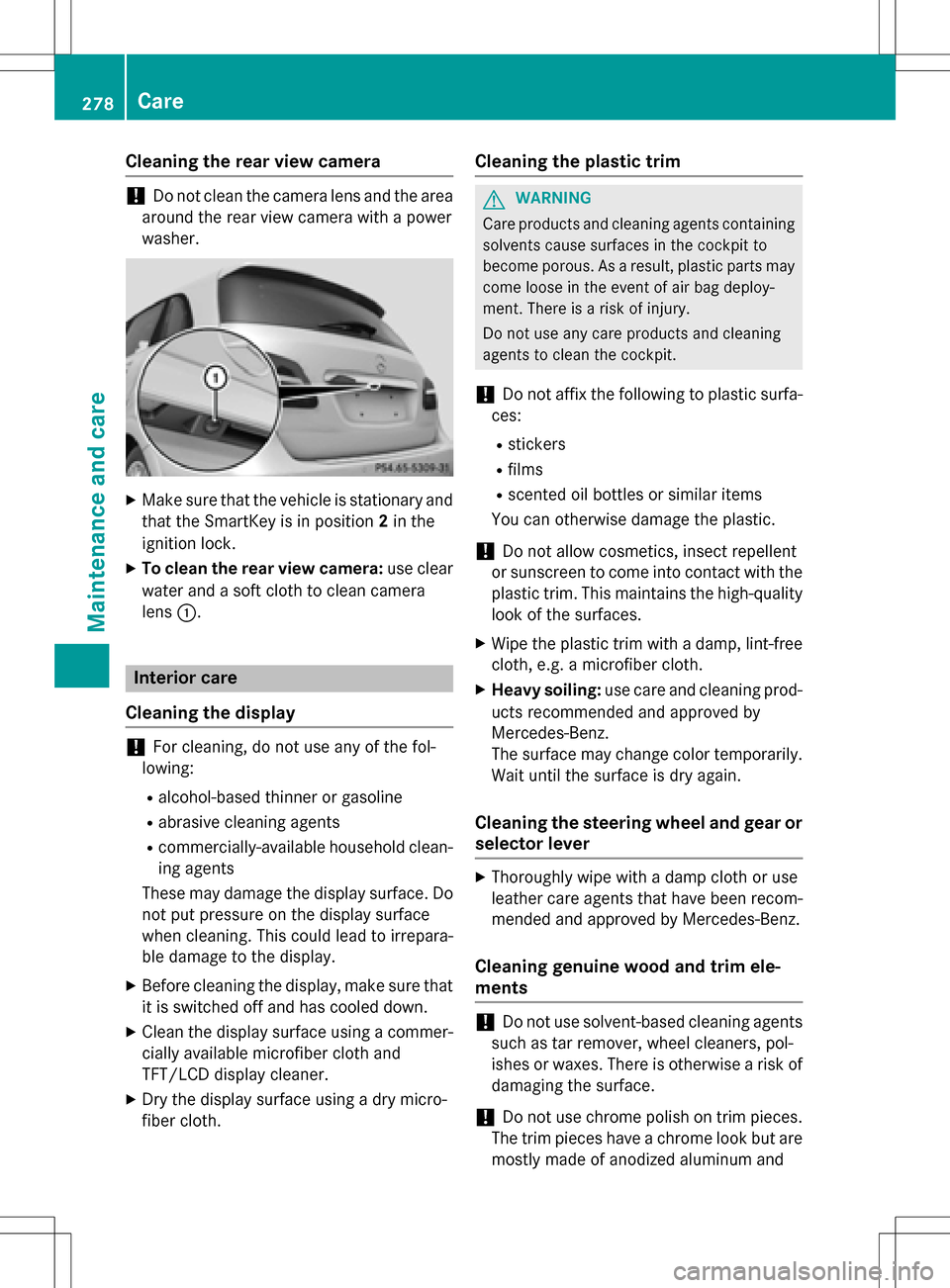
Cleaning the rear view camera
!Do not clean the camera lens and the area
around the rear view camera with a power
washer.
XMake sure that the vehicle is stationary and that the SmartKey is in position 2in the
ignition lock.
XTo clean the rear view camera: use clear
water and a soft cloth to clean camera
lens :.
Interior care
Cleaning the display
!For cleaning, do not use any of the fol-
lowing:
Ralcohol-based thinner or gasoline
Rabrasive cleaning agents
Rcommercially-available household clean-
ing agents
These may damage the display surface. Do not put pressure on the display surface
when cleaning. This could lead to irrepara-
ble damage to the display.
XBefore cleaning the display, make sure thatit is switched off and has cooled down.
XClean the display surface using a commer-
cially available microfiber cloth and
TFT/LCD display cleaner.
XDry the display surface using a dry micro-
fiber cloth.
Cleaning the plastic trim
GWARNING
Care products and cleaning agents containing solvents cause surfaces in the cockpit to
become porous. As a result, plastic parts may
come loose in the event of air bag deploy-
ment. There is a risk of injury.
Do not use any care products and cleaning
agents to clean the cockpit.
!Do not affix the following to plastic surfa-
ces:
Rstickers
Rfilms
Rscented oil bottles or similar items
You can otherwise damage the plastic.
!Do not allow cosmetics, insect repellent
or sunscreen to come into contact with the
plastic trim. This maintains the high-quality
look of the surfaces.
XWipe the plastic trim with a damp, lint-free
cloth, e.g. a microfiber cloth.
XHeavy soiling: use care and cleaning prod-
ucts recommended and approved by
Mercedes-Benz.
The surface may change color temporarily.
Wait until the surface is dry again.
Cleaning the steering wheel and gear or
selector lever
XThoroughly wipe with a damp cloth or use
leather care agents that have been recom-
mended and approved by Mercedes-Benz.
Cleaning genuine wood and trim ele-
ments
!Do not use solvent-based cleaning agents
such as tar remover, wheel cleaners, pol-
ishes or waxes. There is otherwise a risk of
damaging the surface.
!Do not use chrome polish on trim pieces.
The trim pieces have a chrome look but are
mostly made of anodized aluminum and
278Care
Maintenance and care
Page 281 of 342
can lose their shine if chrome polish is
used. Use a damp, lint-free cloth instead
when cleaning the trim pieces.
If the chrome-plated trim pieces are very
dirty, you can use a chrome polish. If you
are unsure as to whether the trim pieces
are chrome-plated or not, consult an
authorized Mercedes-Benz Center.
XWipe the wooden trim and trim pieces with
a damp, lint-free cloth, e.g. a microfiber
cloth.
XHeavy soiling:use care and cleaning prod-
ucts recommended and approved by
Mercedes-Benz.
Cleaning the seat covers
General notes
!Do not use a microfiber cloth to clean
covers made out of real leather, artificial
leather or DINAMICA. If used often, these
can damage the cover.
Note that regular care is essential to ensure
that the appearance and comfort of the cov-
ers is retained over time.
Genuine leather seat covers
!To retain the natural appearance of the
leather, observe the following cleaning
instructions:
RClean genuine leather covers carefully
with a damp cloth and then wipe the cov-
ers down with a dry cloth.
RMake sure that the leather does not
become soaked. It may otherwise
become rough and cracked.
ROnly use leather care agents that have
been tested and approved by Mercedes-
Benz. You can obtain these from a quali-
fied specialist workshop.
Leather is a natural product.
It exhibits natural surface characteristics, for
example:
Rdifferences in the texture
Rmarks caused by growth and injury
Rslight nuances of color
These are characteristics of leather and not
material defects.
Seat covers of other materials
!Observe the following when cleaning:
Rclean artificial leather covers with a cloth
moistened with a solution containing 1% detergent (e.g. dish washing liquid).
Rclean cloth covers with a microfiber cloth
moistened with a solution containing 1%
detergent (e.g. dish washing li quid). Rub
carefully and always wipe entire seat sec-
tions to avoid leaving visible lines. Leave
the seat to dry afterwards. Cleaning
results depend on the type of dirt and
how long it has been there.
Rclean DINAMICA covers with a damp
cloth. Make sure that you wipe entire
seat sections to avoid leaving visible
lines.
Cleaning the seat belts
GWARNING
Seat belts can become severely weakened if
bleached or dyed. This could cause the seat
belts to tear or fail, for instance, in the event of an accident. This poses an increased risk of
injury or fatal injury.
Never bleach or dye the seat belts.
!Do not clean the seat belts using chemical
cleaning agents. Do not dry the seat belts
by heating at temperatures above 176 ‡
(80 †) or in direct sunlight.
XUse clean, lukewarm water and soap solu-
tion.
Care279
Maintenance and care
Z
Page 288 of 342
If a tire pressure of 200 kPa (2.0 bar/29 psi)
has not been attained after five minutes, see
"Tire pressure not reached" (
Ypage 286).
If tire sealant has escaped, clean it off affec-
ted areas as quickly as possible. Use plain
water if possible.
If your clothes are soiled with tire sealant,
have them cleaned with perchloroethylene at
a dry cleaner as soon as possible.
Tire pressure not reached
If a tire pressure of 200 kPa (2.0 bar/29 psi)
has not been attained after ten minutes:
XSwitch off the tire inflation compressor.
XUnscrew the filler hose from the valve of
the faulty tire.
Note that tire sealant may escape when you
unscrew the filler hose.
XVery slowly drive forwards or reverse
approximately 30 ft (10 m).
XPump up the tire again.
After a maximum of ten minutes, the tire
pressure must be at least 200 kPa (2.0 bar/ 29 psi).
GWARNING
If the required tire pressure is not reached
after the specified time, the tire is too badly
damaged. The tire sealant cannot repair the
tire in this instance. Damaged tires and a tire
pressure that is too low can significantly
impair the vehicle's braking and driving char-
acteristics. There is a risk of accident.
Do not continue driving. Contact a qualified
specialist workshop.
Tire pressure reached
GWARNING
A tire temporarily sealed with tire sealant
impairs the driving characteristics and is not
suitable for higher speeds. There is a risk of
accident.
You should therefore adapt your driving style
accordingly and drive carefully. Do not exceed
the specified maximum speed with a tire that
has been repaired using tire sealant.
The maximum permissible speed for a tire
sealed with tire sealant is 50 mph (80 km/h).
The upper part of the TIREFIT sticker must be affixed to the instrument cluster in the driv-
er's field of vision.
!Residue from the tire sealant may come
out of the filler hose after use. This could
cause stains.
Therefore, place the filler hose in the plastic
bag which contained the TIREFIT kit.
HEnvironmental note
Have the used tire sealant bottle disposed of
professionally, e.g. at a qualified specialist
workshop.
If a tire pressure of 200 kPa (2.0 bar/29 psi)
has been attained after ten minutes:
XSwitch off the tire inflation compressor.
XUnscrew the filler hose from the valve of
the faulty tire.
XStow the tire sealant bottle and the tire
inflation compressor.
XPull away immediately.
XStop after driving for approximately ten
minutes and check the tire pressure with
the tire inflation compressor.
The tire pressure must now be at least
130 kPa (1.3 bar/19 psi).
GWARNING
If the required tire pressure is not reached
after driving for a short period, the tire is too
badly damaged. The tire sealant cannot repair
the tire in this instance. Damaged tires and a
tire pressure that is too low can significantly
impair the vehicle's braking and driving char-
acteristics. There is a risk of accident.
Do not continue driving. Contact a qualified
specialist workshop.
iIn cases such as the one mentioned
above, contact an authorized Mercedes-
286Flat tire
Breakdown assistance
Page 324 of 342
Curb weight
The weight of a vehicle with standard equip-
ment including the maximum capacity of fuel,
oil and coolant. It also includes the air-condi-
tioning system and optional equipment if
these are installed in the vehicle, but does not
include passengers or luggage.
Maximum load rating
The maximum tire load is the maximum per-
missible weight in kilograms or lbs for which a
tire is approved.
Maximum permissible tire pressure
Maximum permissible tire pressure for one
tire.
Maximum load on one tire
Maximum load on one tire. This is calculated
by dividing the maximum axle load of one axle
by two.
PSI (pounds per square inch)
A standard unit of measure for tire pressure.
Aspect ratio
Relationship between tire height and tire
width in percent.
Tire pressure
This is pressure inside the tire applying an
outward force to each square inch of the tire's
surface. The tire pressure is specified in
pounds per square inch (psi), in kilopascal
(kPa) or in bar. The tire pressure should only
be corrected when the tires are cold.
Cold tire pressure
The tires are cold:
Rif the vehicle has been parked with the tires
out of direct sunlight for at least three
hours and
Rif the vehicle has not been driven further
than 1 mile (1.6 km) Tread
The part of the tire that comes into contact
with the road.
Bead
The tire bead ensures that the tire sits
securely on the wheel. There are several steel
wires in the bead to prevent the tire from
coming loose from the wheel rim.
Sidewall
The part of the tire between the tread and the
bead.
Weight of optional extras
The combined weight of those optional extras
that weigh more than the replaced standard
parts and more than 2.3 kg (5 lbs). These
optional extras, such as high-performance
brakes, level control, a roof rack or a high-
performance battery, are not included in the
curb weight and the weight of the accesso-
ries.
TIN (Tire Identification Number)
This is a unique identifier which can be used
by a tire manufacturer to identify tires, for
example for a product recall, and thus identify
the purchasers. The TIN is made up of the
manufacturer's identity code, tire size, tire
type code and the manufacturing date.
Load bearing index
The load bearing index (also load index) is a
code that contains the maximum load bearing
capacity of a tire.
Traction
Traction is the result of friction between the
tires and the road surface.
Treadwear indicators
Narrow bars (tread wear bars) that are dis-
tributed over the tire tread. If the tire tread is
level with the bars, the wear limit of áin
(1.6 mm) has been reached.
322All about wheels and tires
Wheels and tires
Page 325 of 342
Occupant distribution
The distribution of occupants in a vehicle at
their designated seating positions.
Total load limit
Nominal load and luggage load plus 68 kg
(150 lbs) multiplied by the number of seats in
the vehicle.
Changing a wheel
Flat tire
The "Breakdown assistance" section
(
Ypage 282) contains information and notes
on how to deal with a flat tire. Information on driving with MOExtended tires in the event of
a flat tire can be found under "MOExtended
tires (tires with run-flat characteristics"
(
Ypage 283).
Rotating the wheels
GWARNING
Interchanging the front and rear wheels may
severely impair the driving characteristics if
the wheels or tires have different dimensions. The wheel brakes or suspension components
may also be damaged. There is a risk of acci-
dent.
Rotate front and rear wheels only if the wheels and tires are of the same dimensions.
!On vehicles equipped with a tire pressure
monitor, electronic components are loca-
ted in the wheel.
Tire-mounting tools should not be used
near the valve. This could damage the elec- tronic components.
Only have tires changed at a qualified spe-
cialist workshop.
Observe the instructions and safety notes in
the "Changing a wheel" section (
Ypage 323).
The wear patterns on the front and rear tires
differ, depending on the operating conditions.
Rotate the wheels before a clear wear pattern has formed on the tires. Front tires typically
wear more on the shoulders and the rear tires
in the center.
On vehicles that have the same size front and
rear wheels, you can rotate the wheels
according to the intervals in the tire manu-
facturer's warranty book in your vehicle docu-
ments. If no warranty book is available, the
tires should be rotated every 3,000 to
6,000 miles (5,000 to 10,000 km). Depending
on tire wear, this may be required earlier. Do
not change the direction of wheel rotation.
Clean the contact surfaces of the wheel and
the brake disc thoroughly every time a wheel
is rotated. Check the tire pressure and reac-
tivate the tire pressure monitor if necessary.
Direction of rotation
Tires with a specified direction of rotation
have additional benefits, e.g. if there is a risk
of hydroplaning. These advantages can only
be gained if the tires are installed correspond-
ing to the direction of rotation.
An arrow on the sidewall of the tire indicates
its correct direction of rotation.
Storing wheels
Store wheels that are not being used in a cool,
dry and preferably dark place. Protect the
tires against oil and grease.
Mounting a wheel
Preparing the vehicle
XStop the vehicle on solid, non-slippery and
level ground.
XApply the electric parking brake manually.
XBring the front wheels into the straight-
ahead position.
XShift the transmission to position P.
XSwitch off the drive system.
Changing a wheel323
Wheels and tires
Z
Page 328 of 342
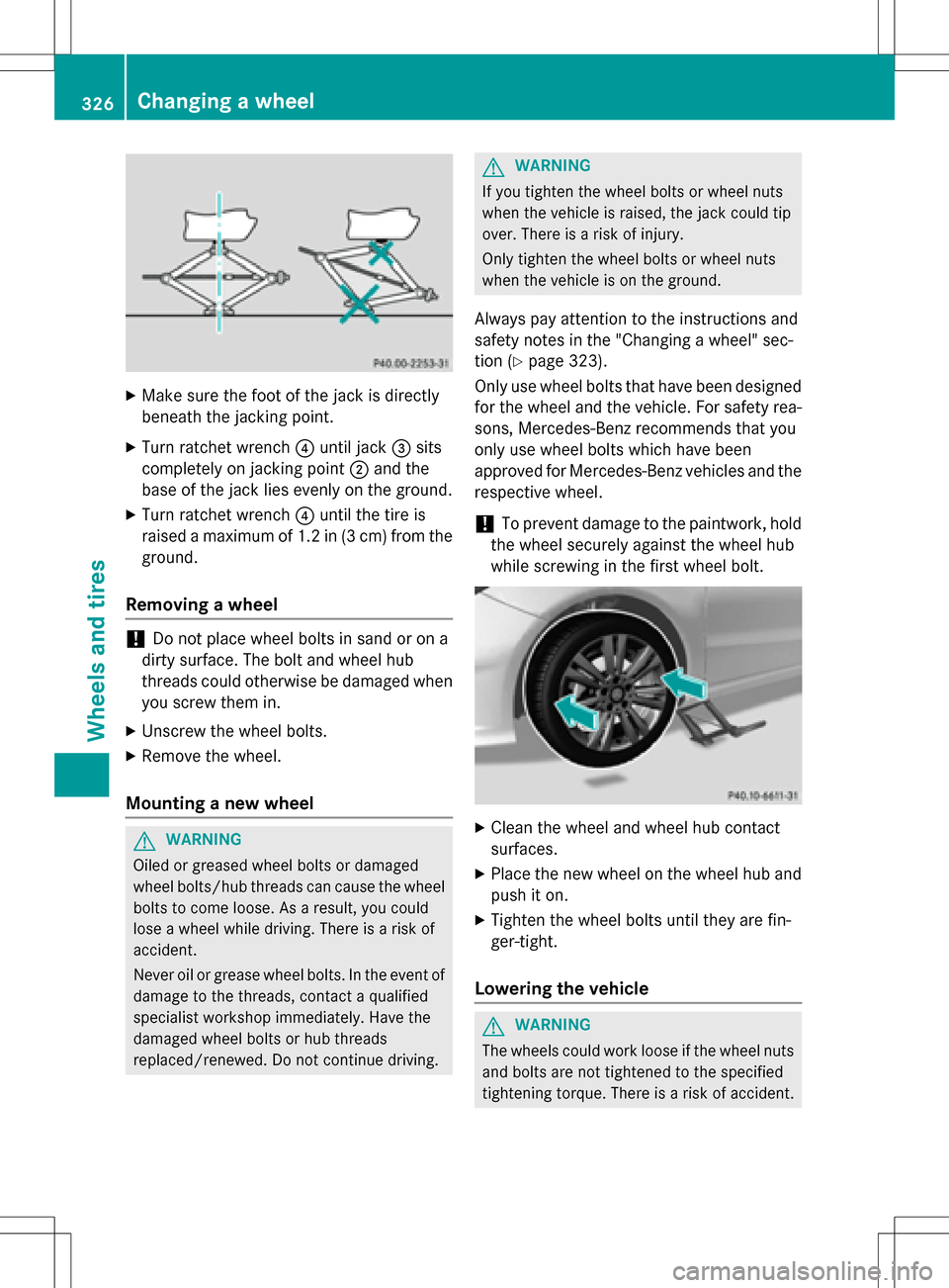
XMake sure the foot of the jack is directly
beneath the jacking point.
XTurn ratchet wrench?until jack =sits
completely on jacking point ;and the
base of the jack lies evenly on the ground.
XTurn ratchet wrench ?until the tire is
raised a maximum of 1.2 in (3 cm) from the ground.
Removing a wheel
!Do not place wheel bolts in sand or on a
dirty surface. The bolt and wheel hub
threads could otherwise be damaged when
you screw them in.
XUnscrew the wheel bolts.
XRemove the wheel.
Mounting a new wheel
GWARNING
Oiled or greased wheel bolts or damaged
wheel bolts/hub threads can cause the wheel bolts to come loose. As a result, you could
lose a wheel while driving. There is a risk of
accident.
Never oil or grease wheel bolts. In the event of
damage to the threads, contact a qualified
specialist workshop immediately. Have the
damaged wheel bolts or hub threads
replaced/renewed. Do not continue driving.
GWARNING
If you tighten the wheel bolts or wheel nuts
when the vehicle is raised, the jack could tip
over. There is a risk of injury.
Only tighten the wheel bolts or wheel nuts
when the vehicle is on the ground.
Always pay attention to the instructions and
safety notes in the "Changing a wheel" sec-
tion (
Ypage 323).
Only use wheel bolts that have been designed for the wheel and the vehicle. For safety rea-
sons, Mercedes-Benz recommends that you
only use wheel bolts which have been
approved for Mercedes-Benz vehicles and the
respective wheel.
!To prevent damage to the paintwork, hold
the wheel securely against the wheel hub
while screwing in the first wheel bolt.
XClean the wheel and wheel hub contact
surfaces.
XPlace the new wheel on the wheel hub and push it on.
XTighten the wheel bolts until they are fin-
ger-tight.
Lowering the vehicle
GWARNING
The wheels could work loose if the wheel nuts and bolts are not tightened to the specified
tightening torque. There is a risk of accident.
326Changing a wheel
Wheels and tires