trunk MERCEDES-BENZ B-Class ELECTRIC 2016 W246 Owner's Manual
[x] Cancel search | Manufacturer: MERCEDES-BENZ, Model Year: 2016, Model line: B-Class ELECTRIC, Model: MERCEDES-BENZ B-Class ELECTRIC 2016 W246Pages: 342, PDF Size: 7.53 MB
Page 19 of 342
Tire bead (definition) ...................... 322
Tire pressure (definition) ................ 322
Tire pressures (recommended) ...... 321
Tire size (data) ............................... 327
Tire size designation, load-bearing
capacity, speed rating .................... 317
Tire tread ....................................... 303
Tire tread (definition) ..................... 322
Total load limit (definition) ............. 323
Traction ......................................... 316
Traction (definition) ....................... 322
Tread wear ..................................... 316
Uniform Tire Quality Grading
Standards ...................................... 315
Uniform Tire Quality Grading
Standards (definition) .................... 321
Wear indicator (definition) ............. 322
Wheel and tire combination ........... 329
Wheel rim (definition) .................... 321
see Flat tire
Top Tether ............................................ 59
Towing away
Important safety guidelines ........... 294
Installing the towing eye ................ 296
Removing the towing eye ............... 296
Transporting the vehicle ................ 297
With both axles on the ground ....... 296
With front axle raised ..................... 297
With the rear axle raised ................ 297
Towing eye ......................................... 282
Trailer hitch ......................................... 25
Trailer tow hitch .................................. 25
Transmission
DIRECT SELECT lever ..................... 134
Drive program ................................ 137
Driving tips .................................... 137
Engaging the drive position ............ 136
Engaging the park position ............ 135
Holding the vehicle stationary on
uphill gradients .............................. 137
Kickdown ....................................... 137
Overview ........................................ 134
Program selector button ................ 137
Shifting to neutral .......................... 135
Transmission position display ......... 134
Transmission position display
(DIRECT SELECT lever) ...................... 134Transmission positions
....................136
Transporting the vehicle .................. 297
Trim pieces (cleaning instruc-
tions) .................................................. 278
Trip computer (on-board com-
puter) .................................................. 187
Trip odometer
Calling up ....................................... 187
Resetting (on-board computer) ...... 189
Trunk lid
see Tailgate
Trunk load (maximum) ...................... 338
Turn signals
Changing bulbs (front) ................... 107
Display message ............................ 215
Switching on/off ........................... 102
Two-way radio
Frequencies ................................... 332
Installation ..................................... 332
Transmission output (maximum) .... 332
Type identification plate
see Vehicle identification plate
U
UnlockingEmergency unlocking ....................... 80
From inside the vehicle (central
unlocking button) ............................. 80
V
Vanity mirror (in the sun visor) ........ 253
Vehicle
Correct use ...................................... 26
Data acquisition ............................... 27
Display message ............................ 225
Equipment ....................................... 21
Individual settings .......................... 195
Limited Warranty ............................. 27
Loading .......................................... 312
Locking (in an emergency) ............... 81
Locking (SmartKey) .......................... 72
Lowering ........................................ 326
Maintenance .................................... 22
Parking for a long period ................ 156
Raising ........................................... 324
Reporting problems ......................... 26
Index17
Page 20 of 342
Securing from rolling away ............ 324
Starting .......................................... 132
Transporting .................................. 297
Unlocking (in an emergency) ........... 80
Unlocking (SmartKey) ...................... 72
Vehicle data ................................... 338
Vehicle data
Roof load (maximum) ..................... 338
Trunk load (maximum) ................... 338
Vehicle dimensions ........................... 338
Vehicle emergency locking ................ 81
Vehicle Homepage
Data protection .............................. 152
Functions ....................................... 153
General information ....................... 152
Internet connection ....................... 153
Vehicle identification number
see VIN
Vehicle identification plate .............. 334
Vehicle tool kit .................................. 282
Ventilation
Setting the vents ........................... 126
Video
Operating the DVD ......................... 191
VIN
Seat ............................................... 334
Type plate ...................................... 334
W
Warning and indicator lampsABS ................................................ 232
Brakes ........................................... 231
Distance warning ........................... 239
ESP
®.............................................. 235
ESP®OFF ....................................... 236
Overview .......................................... 32
PASSENGER AIR BAG ...................... 41
RBS (Recuperative Brake Sys-
tem) ............................................... 231
Restraint system ............................ 238
Seat belt ........................................ 229
Tire pressure monitor .................... 240
Warranty .............................................. 21
Washer fluid
Display message ............................ 227
Wheel and tire combinations
Tires ............................................... 329 Wheel bolt tightening torque
........... 326
Wheel chock ...................................... 324
Wheels
Changing a wheel .......................... 323
Checking ........................................ 303
Cleaning ......................................... 276
General notes ................................ 327
Important safety notes .................. 302
Information on driving .................... 302
Interchanging/changing ................ 323
Mounting a new wheel ................... 326
Removing a wheel .......................... 326
Storing ........................................... 323
Tightening torque ........................... 326
Wheel size/tire size ....................... 327
Window curtain air bag
Display message ............................ 211
Operation ......................................... 49
Windows
see Side windows
Windshield
Defrosting ...................................... 121
Windshield washer system
Adding washer fluid ....................... 272
Important safety notes .................. 336
Windshield wipers
Display message ............................ 227
Problem (malfunction) ................... 114
Rear window wiper ........................ 110
Replacing the wiper blades ............ 110
Switching on/off ........................... 109
Winter driving
Slippery road surfaces ................... 161
Snow chains .................................. 305
Winter operation
General notes ................................ 304
Winter tires
M+S tires ....................................... 304
Wiper blades
Cleaning ......................................... 277
Important safety notes .................. 110
Replacing (rear window) ................ 112
Replacing (windshield) ................... 111
Woode n trim (cleaning instruc-
tions) .................................................. 278
Workshop
see Qualified specialist workshop
18Index
Page 76 of 342
For the purposes of activation/deactivation,
the vehicle must not be nearby.
XTo deactivate:press the&button on
the SmartKey twice in rapid succession.
The battery check lamp of the SmartKey
flashes twice briefly and lights up once,
then KEYLESS-GO is deactivated
(
Ypage 75).
XTo activate: press any button on the
SmartKey.
or
XInsert the SmartKey into the ignition lock.
KEYLESS-GO and all of its associated fea-
tures are available again.
KEYLESS-GO start function
General notes
Bear in mind that the drive system can be
started by any of the vehicle occupants if
there is a key in the vehicle.
Changing the settings of the locking
system
You can change the settings of the locking
system. This means that only the driver's door
and the charge socket flap are unlocked when
the vehicle is unlocked. This is useful if you
frequently travel on your own.
XTo change the setting: press and hold the
% and& buttons simultaneously for
approximately six seconds until the battery
check lamp flashes twice (
Ypage 75).
If the setting of the locking system is changed
within the signal range of the vehicle, press-
ing the &or% button:
Rlocks or
Runlocks the vehicle The SmartKey now functions as follows:
XTo unlock:
press the%button once.
XTo unlock centrally: press the%but-
ton twice.
XTo lock centrally: press the&button.
The KEYLESS-GO function is changed as fol-
lows:
XTo unlock the driver's door: touch the
inner surface of the door handle on the
driver's door.
XTo unlock centrally: touch the inner sur-
face of the door handle on the front-
passenger door or the rear door.
XTo lock centrally: touch the outer sensor
surface on one of the door handles.
XTo restore the factory settings: press
and hold the %and& buttons simul-
taneously for approximately six seconds
until the battery check lamp flashes twice
(
Ypage 75).
Mechanical key
General notes
If the vehicle can no longer be locked or
unlocked with the SmartKey or KEYLESS-GO,
use the mechanical key.
If you use the mechanical key to unlock and
open the driver's door or the trunk lid, the
anti-theft alarm system will be triggered
(
Ypage 69).
There are several ways to turn off the alarm:
XTo deactivate the alarm with the key:
press the %or& button on the key.
or
XInsert the SmartKey into the ignition lock.
or
XTo deactivate the alarm with KEYLESS-
GO: press the Start/Stop button in the igni-
tion lock. The SmartKey must be in the
vehicle.
74SmartKey
Opening and closing
Page 149 of 342
If you use the supplied 12 A charging cable to
charge a high-voltage battery:
Rthe charge time increases considerably
Relectrical consumption increases consider-
ably
Where possible, charge the high-voltage bat-
tery at a charging station (
Ypage 149). Only
then can certified electrical energy consump-
tion levels be reached.
iThe charging process can vary depending
on the charging station. Therefore, always
observe the local information.
Stowing the charging cable
The charging cable can be stowed in a bag in
the trunk of the vehicle. To do so, the bag
must be secured to the cargo tie-down rings
using the retaining strap provided.
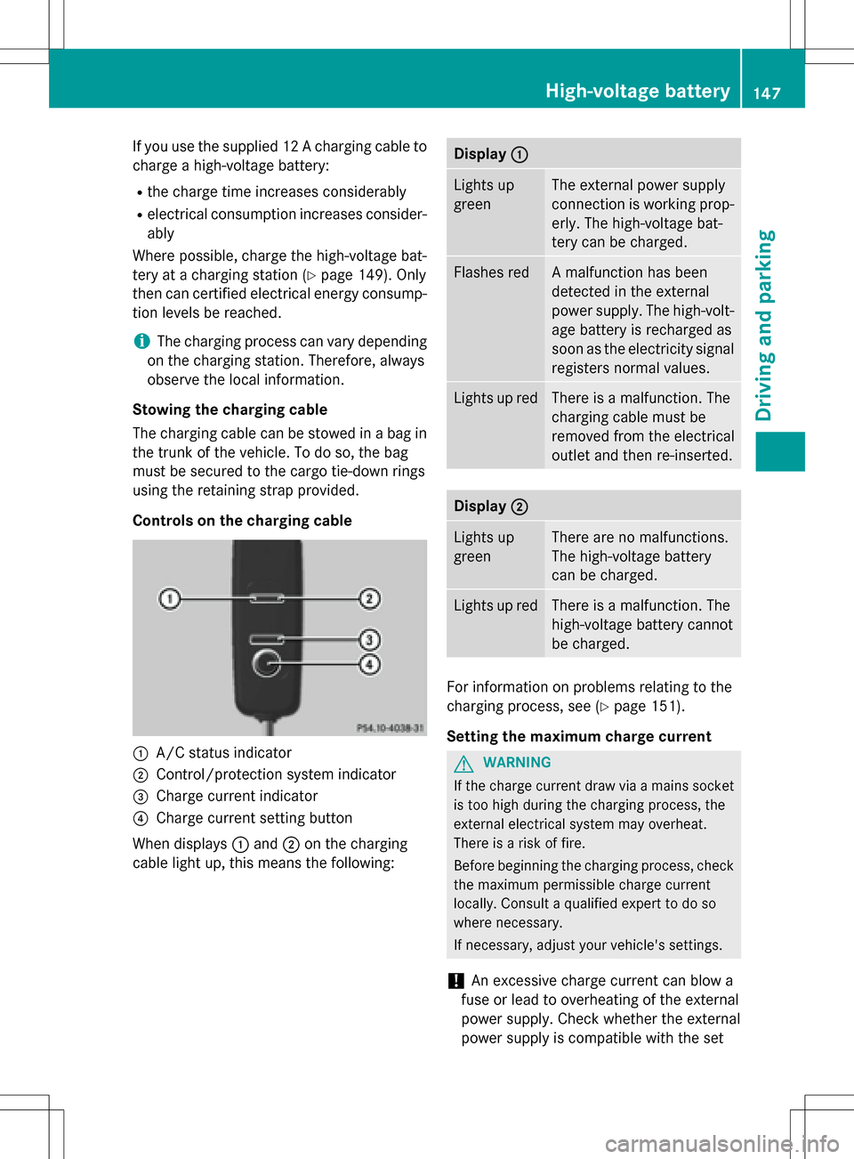
Controls on the charging cable
:A/C status indicator
;Control/protection system indicator
=Charge current indicator
?Charge current setting button
When displays :and ;on the charging
cable light up, this means the following:
Display :
Lights up
greenThe external power supply
connection is working prop-
erly. The high-voltage bat-
tery can be charged.
Flashes redA malfunction has been
detected in the external
power supply. The high-volt-
age battery is recharged as
soon as the electricity signal
registers normal values.
Lights up redThere is a malfunction. The
charging cable must be
removed from the electrical
outlet and then re-inserted.
Display;
Lights up
greenThere are no malfunctions.
The high-voltage battery
can be charged.
Lights up redThere is a malfunction. The
high-voltage battery cannot
be charged.
For information on problems relating to the
charging process, see (
Ypage 151).
Setting the maximum charge current
GWARNING
If the charge current draw via a mains socket
is too high during the charging process, the
external electrical system may overheat.
There is a risk of fire.
Before beginning the charging process, check
the maximum permissible charge current
locally. Consult a qualified expert to do so
where necessary.
If necessary, adjust your vehicle's settings.
!An excessive charge current can blow a
fuse or lead to overheating of the external
power supply. Check whether the external
power supply is compatible with the set
High-voltage battery147
Driving and parking
Z
Page 248 of 342
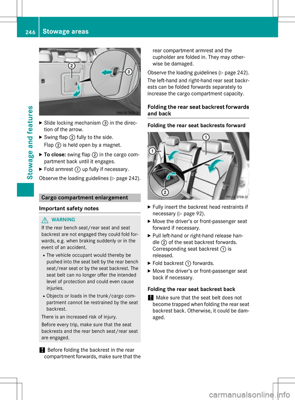
XSlide locking mechanism=in the direc-
tion of the arrow.
XSwing flap ;fully to the side.
Flap ;is held open by a magnet.
XTo close: swing flap ;in the cargo com-
partment back until it engages.
XFold armrest :up fully if necessary.
Observe the loading guidelines (
Ypage 242).
Cargo compartment enlargement
Important safety notes
GWARNING
If the rear bench seat/rear seat and seat
backrest are not engaged they could fold for-
wards, e.g. when braking suddenly or in the
event of an accident.
RThe vehicle occupant would thereby be
pushed into the seat belt by the rear bench
seat/rear seat or by the seat backrest. The
seat belt can no longer offer the intended
level of protection and could even cause
injuries.
RObjects or loads in the trunk/cargo com-
partment cannot be restrained by the seat
backrest.
There is an increased risk of injury.
Before every trip, make sure that the seat
backrests and the rear bench seat/rear seat
are engaged.
!Before folding the backrest in the rear
compartment forwards, make sure that the rear compartment armrest and the
cupholder are folded in. They may other-
wise be damaged.
Observe the loading guidelines (
Ypage 242).
The left-hand and right-hand rear seat backr-
ests can be folded forwards separately to
increase the cargo compartment capacity.
Folding the rear seat backrest forwards
and back
Folding the rear seat backrests forward
XFully insert the backrest head restraints if
necessary (
Ypage 92).
XMove the driver's or front-passenger seat
forward if necessary.
XPull left-hand or right-hand release han-
dle ;of the seat backrest forwards.
Corresponding seat backrest :is
released.
XFold backrest :forwards.
XMove the driver's or front-passenger seat
back if necessary.
Folding the rear seat backrest back
!Make sure that the seat belt does not
become trapped when folding the rear seat
backrest back. Otherwise, it could be dam-
aged.
246Stowage areas
Stowage and features
Page 335 of 342
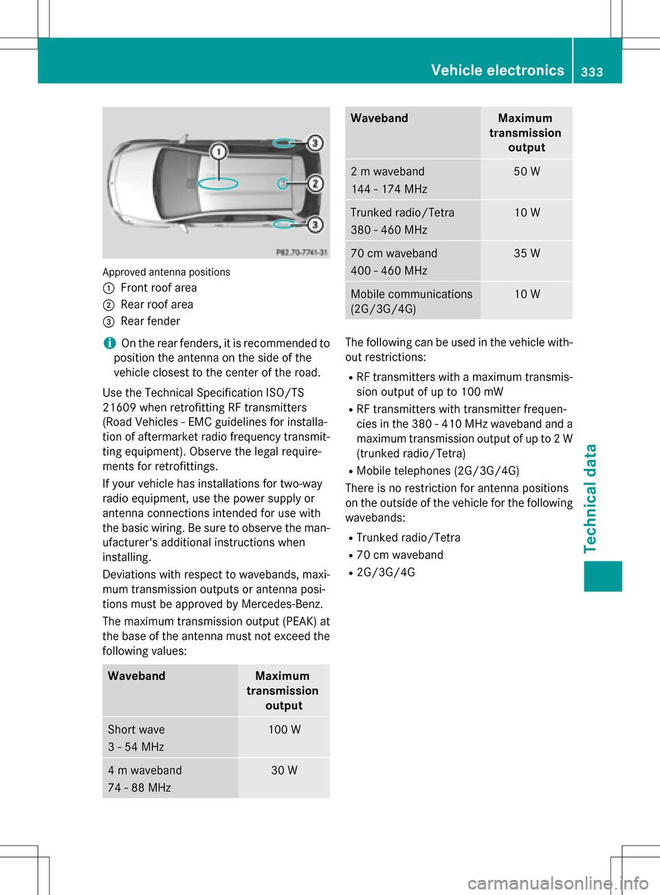
Approved antenna positions
:
Front roof area
;Rear roof area
=Rear fender
iOn the rear fenders, it is recommended to
position the antenna on the side of the
vehicle closest to the center of the road.
Use the Technical Specification ISO/TS
21609 when retrofitting RF transmitters
(Road Vehicles - EMC guidelines for installa-
tion of aftermarket radio frequency transmit-
ting equipment). Observe the legal require-
ments for retrofittings.
If your vehicle has installations for two-way
radio equipment, use the power supply or
antenna connections intended for use with
the basic wiring. Be sure to observe the man- ufacturer's additional instructions when
installing.
Deviations with respect to wavebands, maxi-
mum transmission outputs or antenna posi-
tions must be approved by Mercedes-Benz.
The maximum transmission output (PEAK) at
the base of the antenna must not exceed the
following values:
WavebandMaximum
transmission output
Short wave
3 - 54 MHz100 W
4 m waveband
74 - 88 MHz30 W
WavebandMaximum
transmission output
2 m waveband
144 - 174 MHz50 W
Trunked radio/Tetra
380 - 460 MHz10 W
70 cm waveband
400 - 460 MHz35 W
Mobile communications
(2G/3G/4G)10 W
The following can be used in the vehicle with-
out restrictions:
RRF transmitters with a maximum transmis-
sion output of up to 100 mW
RRF transmitters with transmitter frequen-
cies in the 380 - 410 MHz waveband and a
maximum transmission output of up to 2 W
(trunked radio/Tetra)
RMobile telephones (2G/3G/4G)
There is no restriction for antenna positions
on the outside of the vehicle for the following
wavebands:
RTrunked radio/Tetra
R70 cm waveband
R2G/3G/4G
Vehicle electronics333
Technical data
Z
Page 340 of 342
Vehicle data
General notes
Please note that for the specified vehicle
data:
Rthe heights specified may vary as a result
of:
-tires
-load
-condition of the suspension
-optional equipment
Roptional equipment reduces the maximum
payload.
The range depends on the drive program
selected and can vary due to:
Rhigher and lower outside temperatures
Rthe style of driving
Ractivated electrical consumers
iFurther information on the range can be
found in the Trip
menu (Ypage 188).
Dimensions and weights
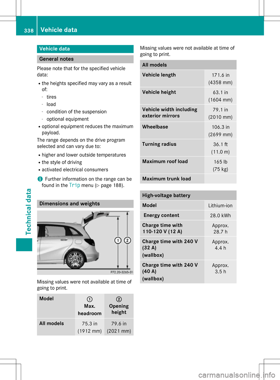
Missing values were not available at time of
going to print.
Model:
Max.
headroom
;
Opening height
All models75.3 in
(1912 mm)79.6 in
(2021 mm)
Missing values were not available at time of
going to print.
All models
Vehicle length171.6 in
(4358 mm)
Vehicle height63.1 in
(1604 mm)
Vehicle width including
exterior mirrors79.1 in
(2010 mm)
Wheelbase106.3 in
(2699 mm)
Turning radius36.1 ft
(11.0 m)
Maximum roof load165 lb
(75 kg)
Maximum trunk load
High-voltage battery
ModelLithium-ion
Energy content28.0 kWh
Charge time with
110-120 V (12 A)Approx. 28.7 h
Charge time with 240 V
(32 A)
(wallbox)Approx. 4.4 h
Charge time with 240 V
(40 A)
(wallbox)Approx.3.5 h
338Vehicle data
Technical data