towing MERCEDES-BENZ B-CLASS HATCHBACK 2011 Service Manual
[x] Cancel search | Manufacturer: MERCEDES-BENZ, Model Year: 2011, Model line: B-CLASS HATCHBACK, Model: MERCEDES-BENZ B-CLASS HATCHBACK 2011Pages: 329, PDF Size: 7.91 MB
Page 261 of 329
on-board voltage is too low, the power to
the sockets is automatically cut. This
ensures that there is sufficient power to
start the engine.
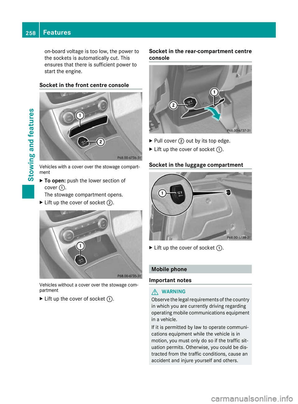
Socket in the front centre console Vehicles with a cover over the stowage compart-
ment
X To open: push the lower section of
cover :.
The stowage compartment opens.
X Lift up the cover of socket ;.Vehicles without a cover over the stowage com-
partment
X
Lift up the cover of socket :.Socket in the rear-compartment centre
console X
Pull cover ;out by its top edge.
X Lift up the cover of socket :.
Socket in the luggage compartment X
Lift up the cover of socket :. Mobile phone
Important notes G
WARNING
Observe the legal requirements of the country
in which you are currently driving regarding
operating mobile communications equipment
in a vehicle.
If it is permitted by law to operate communi-
cations equipment while the vehicle is in
motion, you must only do so if the traffic sit-
uation permits. Otherwise, you could be dis-
tracted from the traffic conditions, cause an
accident and injure yourself and others. 258
FeaturesStowing and features
Page 262 of 329
Two-way radios and fax equipment used with-
out low-reflection exterior aerials can inter-
fere with the vehicle's electronics and thereby
jeopardise the operating safety of the vehicle
and your safety. Therefore, you must only use
this equipment if it is correctly connected to
a separate reflection-free exterior aerial. G
WARNING
Excessive levels of electromagnetic radiation
may cause damage to your health and the
health of others. Using an exterior aerial takes
into account current scientific discussions
relating to the possible health risk posed by
electromagnetic fields.
Mercedes-Benz recommends the use of an
approved exterior aerial. This ensures:
R optimal mobile phone reception quality in
the vehicle
R mutual influences between the vehicle
electronics and mobile phones are mini-
mised
An exterior aerial has the following advan-
tages:
R it conducts the electromagnetic fields gen-
erated by a wireless device to the exterior.
R the field strength in the vehicle interior is
lower than in a vehicle that does not have
an exterior aerial.
More information on suitable mobile phones,
mobile phone brackets and on connecting
Bluetooth ®
capable mobile phones to Audio
20 or COMAND Online can be obtained:
R at your Mercedes-Benz Service Centre
R on the Internet at http://www.mercedes-
benz.com/connect
i There are various mobile phone brackets
that may be fitted to your vehicle; in some
cases, these are country-specific.
i Even if your vehicle is equipped with con-
venience telephony, you can connect a
Bluetooth ®
capable mobile phone to Audio 20 or COMAND Online via the Bluetooth
®
interface.
i The functions and services available when
you use the phone depend on your mobile
phone model and service provider.
Inserting the mobile phone X
Open the telephone compartment
(Y page 246).
X Place the mobile phone bracket into the
pre-installed fitting (see the separate
installation instructions for the mobile
phone fitting).
X Insert the mobile phone into the mobile
phone bracket (see the separate installa-
tion instructions for the mobile phone fit-
ting).
If the mobile phone is inserted in the mobile
phone bracket, you can speak to the person
you are calling using the hands-free system.
i On some mobile phone brackets, you first
have to connect the mobile phone via Blue-
tooth ®
to the mobile phone bracket (see
the separate operating instructions for the
mobile phone bracket).
If this is the case, the mobile phone does
not have to be inserted into the bracket for
you to be able to use the telephone func-
tions. However, the charging function and
aerial function are not available.
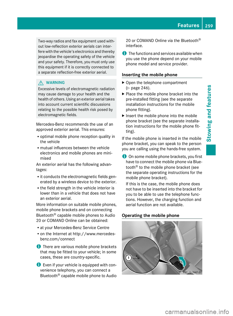
Operating the mobile phone Features
259Stowing and features Z
Page 263 of 329
X
To fold the bracket up: press button:.
X To fold the bracket down: press the
bracket down and allow it to engage.
You can fold the pre-installed bracket up to
improve access to the stowage space
beneath it. Depending on the vehicle's equip-
ment, a USB connection and an AUX-IN con-
nection/Media Interface are fitted in the
stowage compartment (Y page 246).
You can operate the telephone using the
6 and~ buttons on the multifunction
steering wheel. You can operate othe rmobile
phone functions via the on-board computer
(Y page 196).
If you take the key out of the ignition lock, the
mobile phone stays on but you can no longer
use the hands-free system.
If you are making a call and you would like to
take the key out of the ignition lock, first
remove the mobile phone from the bracket.
Otherwise, the call will be ended.
i When a mobile phone bracket is used that
is connected to the mobile phone via Blue-
tooth ®
: if you want to continue a call in
"Private mode", you have to perform the
necessary steps on the mobile phone (see
the separate mobile phone operating
instructions). Floormat on the driver's side
G
WARNING
Make sure that there is sufficient clearance
around the pedals when floormats are used,
and that the floormats are properly secured.
The floormats must be correctly secured at all
times using the securing knob and retainers.
Before you drive off, check the floormats and
secure them if necessary. Afloormat which is
not properly secured can slip and thereby
interfere with the movemen tofthe pedals.
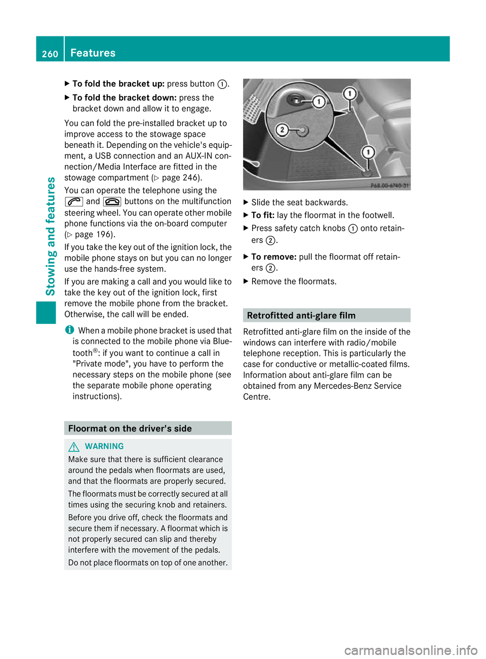
Do not place floormats on top of one another. X
Slide the seat backwards.
X To fit: lay the floormat in the footwell.
X Press safety catch knobs :onto retain-
ers ;.
X To remove: pull the floormat off retain-
ers ;.
X Remove the floormats. Retrofitted anti-glare film
Retrofitted anti-glare film on the inside of the
windows can interfere with radio/mobile
telephone reception. This is particularly the
case for conductive or metallic-coated films.
Information about anti-glare film can be
obtained from any Mercedes-Benz Service
Centre. 260
FeaturesStowing and features
Page 276 of 329
Useful information
............................274
Where will I find...? ...........................274
Flat tyre ............................................. 276
Battery ............................................... 280
Jump-starting .................................... 283
Towing and tow-starting ..................284
Electrical fuses ................................. 287 273Breakdown assistance
Page 278 of 329
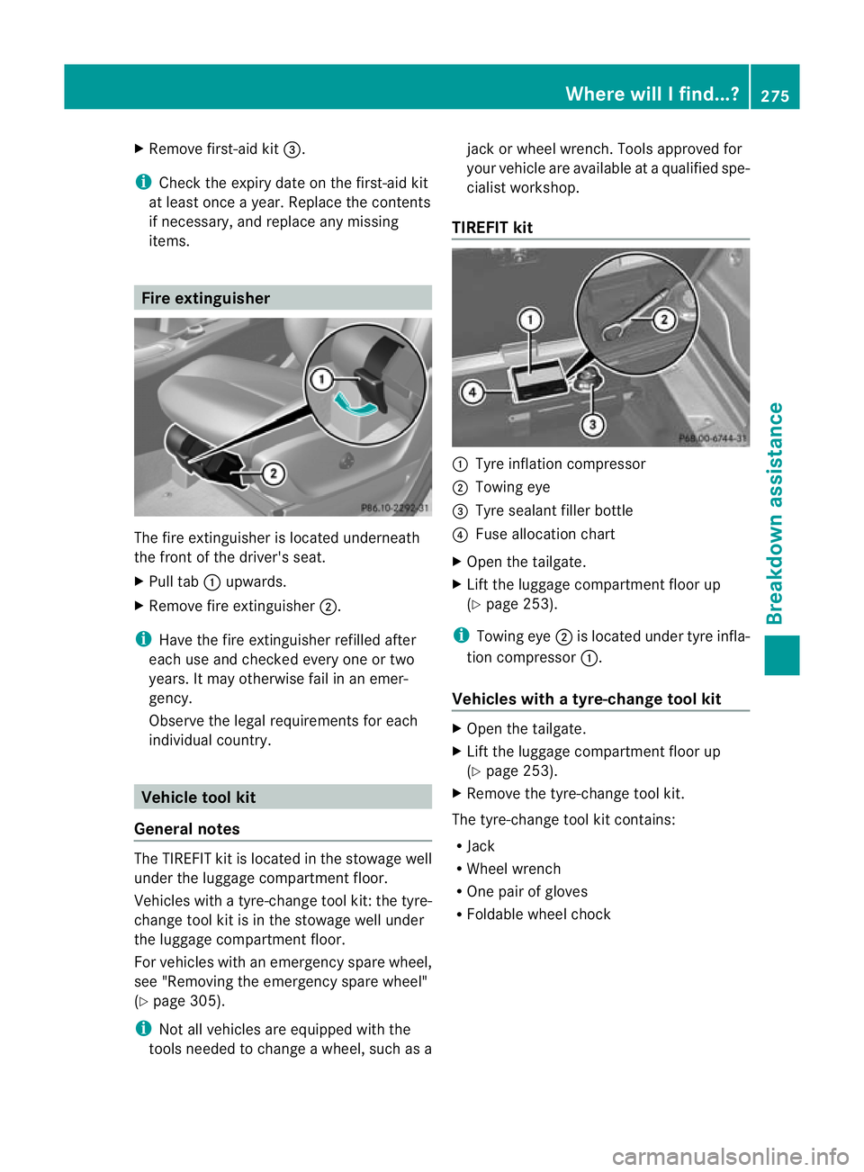
X
Remove first-aid kit =.
i Chec kthe expiry date on the first-aid kit
at least once a year. Replace the contents
if necessary, and replace any missing
items. Fire extinguisher
The fire extinguisher is located underneath
the front of the driver's seat.
X
Pull tab :upwards.
X Remove fire extinguisher ;.
i Have the fire extinguisher refilled after
each use and checked every one or two
years. It may otherwise fail in an emer-
gency.
Observe the legal requirements for each
individual country. Vehicle tool kit
General notes The TIREFIT kit is located in the stowage well
under the luggage compartmentf loor.
Vehicles with a tyre-change tool kit :the tyre-
change tool kit is in the stowage well under
the luggage compartmentf loor.
For vehicles with an emergency spare wheel,
see "Removing the emergency spare wheel"
(Y page 305).
i Not all vehicles are equipped with the
tools needed to change a wheel, such as a jac
korw heel wrench. Tools approved for
your vehicle are available at a qualified spe-
cialist workshop.
TIREFIT kit :
Tyre inflation compressor
; Towing eye
= Tyre sealant filler bottle
? Fuse allocation chart
X Open the tailgate.
X Lift the luggage compartmentf loor up
(Y page 253).
i Towing eye ;is located under tyre infla-
tion compressor :.
Vehicles with a tyre-change tool kit X
Open the tailgate.
X Lift the luggage compartmen tfloor up
(Y page 253).
X Remove the tyre-change tool kit.
The tyre-change tool kit contains:
R Jack
R Wheel wrench
R One pair of gloves
R Foldable wheel chock Where will I find...?
275Breakdown assistance
Page 287 of 329
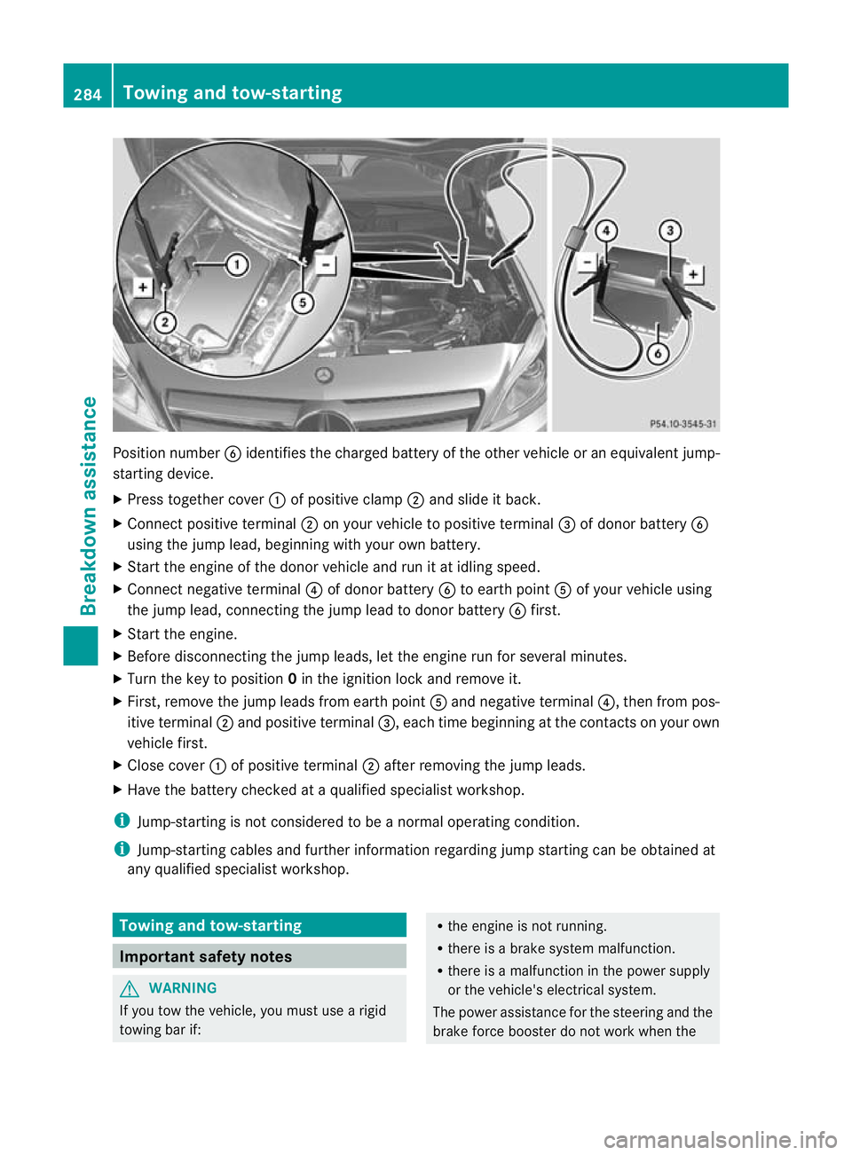
Position number
Bidentifies the charged battery of the other vehicle or an equivalent jump-
starting device.
X Press together cover :of positive clamp ;and slide it back.
X Connec tpositive terminal ;on your vehicle to positive terminal =of donor battery B
using the jump lead, beginning with your own battery.
X Start the engine of the donor vehicle and run it at idling speed.
X Connect negative terminal ?of donor battery Bto earth point Aof your vehicle using
the jump lead, connectingt he jump lead to donor battery Bfirst.
X Start the engine.
X Before disconnecting the jump leads, let the engine run for several minutes.
X Turn the key to position 0in the ignition lock and remove it.
X First, remove the jump leads from earth point Aand negative terminal ?, then from pos-
itive terminal ;and positive terminal =, each time beginning at the contacts on your own
vehicle first.
X Close cover :of positive terminal ;after removing the jump leads.
X Have the battery checked at a qualified specialist workshop.
i Jump-starting is not considered to be a normal operating condition.
i Jump-starting cables and further information regarding jump starting can be obtained at
any qualified specialist workshop. Towing and tow-starting
Important safety notes
G
WARNING
If you tow the vehicle, you must use a rigid
towing bar if: R
the engine is not running.
R there is a brake system malfunction.
R there is a malfunction in the power supply
or the vehicle's electrical system.
The power assistance for the steering and the
brake force booster do not work when the 284
Towing and tow-startingBreakdown assistance
Page 288 of 329
engine is not running. You will need more
force to steer and brake, you may have to
depress the brake pedal with maximum force.
Before towing away, make sure that the steer-
ing can be moved and is not locked.
If you tow or tow-start another vehicle, its
weight must not exceed the maximum per-
missible gross vehicle weight of your vehicle. G
WARNING
The vehicle is braked when the HOLD function
or DISTRONIC PLUS is activated. Therefore,
deactivat eHOLD and DISTRONIC PLUS if the
vehicle is to be towed.
! You may tow the vehicle for a maximum
of 50km. A towing speed of 50 km/h must
not be exceeded.
For towing distances over 50 km, the front
axle or the entire vehicle must be raised
and transported.
! Only secure the tow rope or towing bar to
the towing eyes. The vehicle may otherwise
be damaged.
! Do not use the towing eye for recovery,
as this could damage the vehicle. If in
doubt, recover the vehicle with a crane.
! Pull away smoothly when towing away or
tow-starting a vehicle. If the tractive power
is too high, the vehicles could be damaged.
! Vehicles with automatic transmission
must not be tow-started. The transmission
may otherwise be damaged.
Observe the legal requirements for the rele-
vant countries when towing and tow-starting.
It is better to have the vehicle transported
than to have it towed.
Vehicles with automatic transmission:
when towing a vehicle, the transmission must
be in position N. The battery must be connected and charged.
Otherwise, you:
R
cannot turn the key in the ignition lock to
position 2
R vehicles with automatic transmission:
cannot shift the transmission to position N
i Deactivate the automatic locking feature
(Y page 203). You could otherwise be
locked out when pushing or towing the
vehicle.
Deactivate tow-away protection
(Y page 69) before the vehicle is towed. Fitting/removing the towing eye
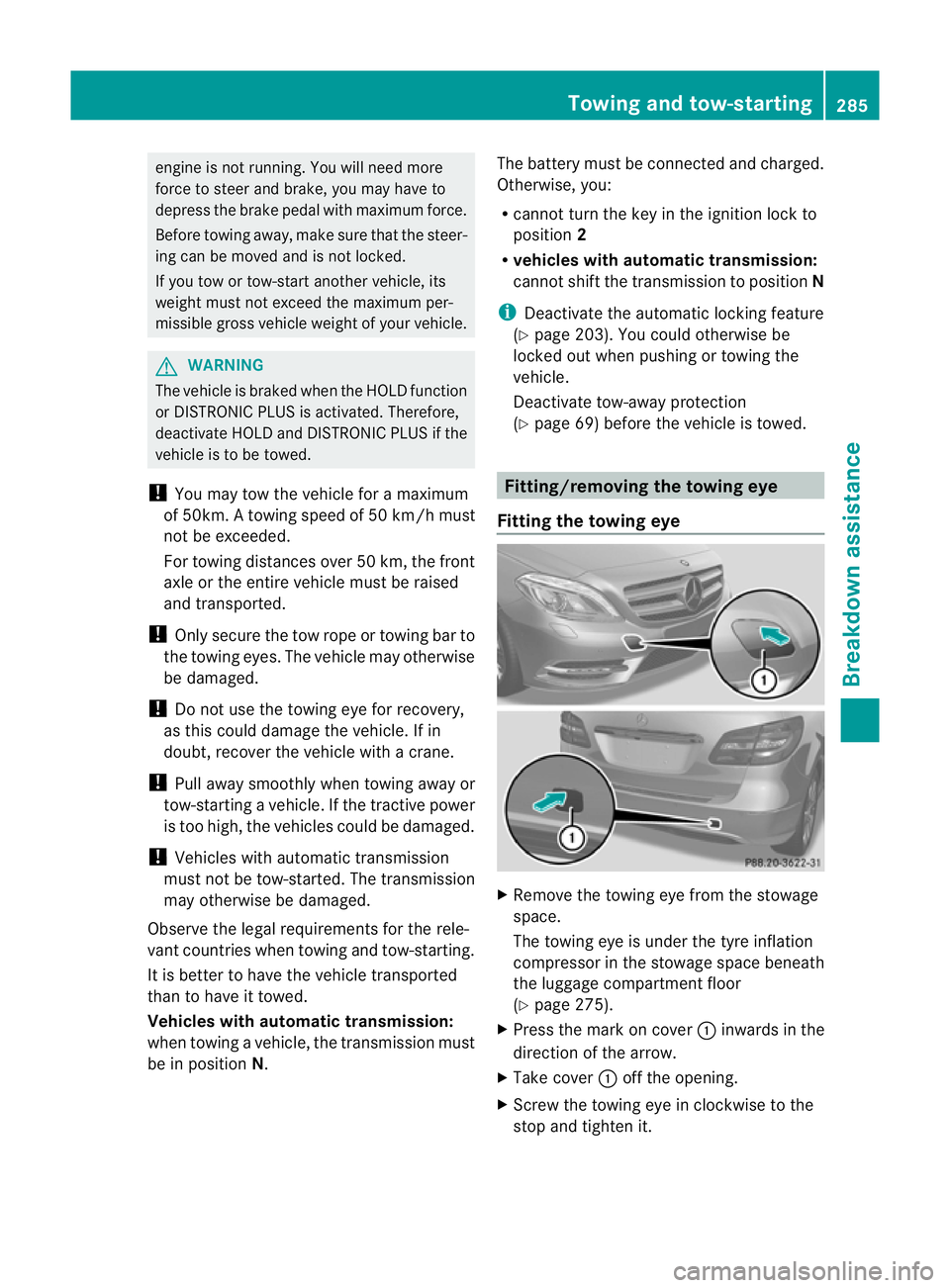
Fitting the towing eye X
Remove the towing eye from the stowage
space.
The towing eye is under the tyre inflation
compressor in the stowage space beneath
the luggage compartment floor
(Y page 275).
X Press the mark on cover :inwards in the
direction of the arrow.
X Take cover :off the opening.
X Screw the towing eye in clockwise to the
stop and tighten it. Towing and tow-starting
285Breakdown assistance Z
Page 289 of 329
Vehicles with a trailer tow hitch: if you intend
to use the vehicle for towing, fold out the ball
coupling (Y
page 183) and connect the tow-
bar to it.
Removing the towing eye X
Loosen the towing eye and unscrew it.
X Attach cover :to the bumper and press
until it engages.
X Place the towing eye and the tyre inflation
compressor in the stowage space in the
luggage compartment under the luggage
compartment floor (Y page 274).Towing the vehicle with the front axle
raised
! The ignition must be switched off if you
are towing the vehicle with the front axle
raised. Intervention by ESP ®
could other-
wise damage the brake system.
X Turn the key to position 2in the ignition
lock.
X When the vehicle is stationary, depress the
brake pedal and keep it depressed.
X Vehicles with manual transmission:
shift to neutral.
or
X Vehicles with automatic transmission:
shift the automatic transmission to posi-
tion P.
X Release the brake pedal.
X Release the electric parking brake.
X Deactivate automatic locking
(Y page 203).
X Switch on the hazard warning lamps
(Y page 99).
X Turn the key in the ignition lock to position
0and leave the key in the ignition lock.
When towing yourv ehicle with the frontaxle
raised, it is important tha tyou observe the
safety instructions (Y page 284). Towing the vehicle with both axles on
the ground
G
WARNING
The power assistance for the steering and the
brake force booster do not work when the
engine is not running. You will then need
much more effort to brake and steer the vehi-
cle. Adapt your style of driving accordingly.
i In order to signal a change of direction
when towing with the hazard warning lamps
switched on, use the combination switch as
usual.Int his case, only the turn signals for
the desired direction flash. When the com-
bination switch is reset, the hazard warning
lamps start flashing again.
Vehicles with automatic transmission: the
automatic transmission automatically shifts
to position Pwhen you open the driver's or
front-passenger door or when you remove the
key from the ignition lock. In order to ensure
that the automatic transmission stays in posi-
tion Nwhen towing the vehicle, you must
observe the following points:
X Make sure that the vehicle is stationary.
X Turn the key to position 2in the ignition
lock.
X Depress and hold the brake pedal.
X Shift the automatic transmission to posi-
tion N.
Vehicles with manual transmission:
X Turn the key to position 2in the ignition
lock.
X Depress and hold the brake pedal.
X Engage neutral.
Vehicles with manualo r automatic trans-
mission:
X Leave the key in position 2in the ignition
lock.
X Release the brake pedal.
X Release the electric parking brake.
X Switch on the hazard warning lamps
(Y page 99). 286
Towing and tow-startingBreakdown assistance
Page 290 of 329
It is important that you observe the safety
instructions when towing away yourv ehicle
(Y page 284). Transporting the vehicle
! Only lash the vehicle down by the wheels
or wheel rims, not by parts of the vehicle
such as axle or steering components. Oth-
erwise, the vehicle could be damaged.
X Vehicles with manual transmission:
shift to neutral.
X Vehicles with automatic transmission:
turn the key to position 2in the ignition
lock.
X Shift the transmission to position N.
As soon as the vehicle is loaded:
X Preven tthe vehicle from rolling away by
applying the electric parking brake.
X Vehicles with manual transmission:
shift to first gear or reverse gear.
X Vehicles with automatic transmission:
shift the transmission to position P.
X Turn the key to position 0in the ignition
lock and remove it.
X Secure the vehicle.
The towing eyes or trailer tow hitch can be
used to pull the vehicle onto a trailer or trans-
porter if you wish to transport it. Tow-starting (emergency engine
starting)
! Vehicles with automatic transmission
must not be tow-started. Otherwise, you
could damage the automatic transmission.
Before tow-starting the following conditions
must be fulfilled:
R the battery is connected.
R the engine has cooled down.
R the catalytic converters have cooled down. X
Switch on the hazard warning lamps
(Y page 99).
X Fit the towing eye (Y page 285).
X Secure the rigid towing bar or the towing
rope.
X Depress and hold the brake pedal.
X Turn the key to position 2in the ignition
lock.
X Depress the clutch pedal and keep it
depressed.
X Engage neutral.
X Release the brake pedal.
X Tow-start the vehicle.
X Engage second gear.
X Release the clutch pedal slowly without
depressing the accelerator pedal.
The engine is started.
X Depress the clutch pedal and shift to neu-
tral.
X Stop at a suitable place.
X Secure the vehicle by applying the electric
parking brake.
X Remove the rigid towing bar or towing rope.
X Remove the towing eye (Y page 286).
X Switch off the hazard warning lamps.
When tow-starting, it is important that you
observe the safety instructions (Y page 284)
and the legal requirements in each respective
country. Electrical fuses
Important safety notes
G
WARNING
Only use fuses that have been approved for
Mercedes-Ben zvehicles and which have the
correct fuse rating for the systems con-
cerned. Do not attempt to repair or bridge
faulty fuses. Using fuses which have not been
approved or attempting to repair or bridge
faulty fuses could cause the fuse to be over-
loaded and result in a fire. Have the cause Electrical fuses
287Breakdown assistance
Z
Page 300 of 329
The tyre pressure warning system does not
warn you of an incorrectly set tyre pressure.
Observe the notes on the recommended tyre
pressure (Y page 295).
The tyre pressure loss warning system does
not replace the need to regularly check your
vehicle's tyre pressures, since an even loss of
pressure on several tyres at the same time
cannot be detected by the tyre pressure loss
warning system.
The tyre pressure monitor is not able to warn
you of a sudden loss of pressure, e.g. if the
tyre is penetrated by a foreign object. In the
event of a sudden loss of pressure, bring the
vehicle to a halt by braking carefully. Avoid
abrupt steering manoeuvres.
The function of the tyre pressure loss warning
system is limited or delaye dif:
R snow chains are fitted to you rvehicle's
tyres.
R road conditions are wintry.
R you are driving on sand or gravel.
R you adopt a very sporty driving style (cor-
nering at high speeds or driving with high
rates of acceleration).
R you are towing a very heavy or large trailer.
R you are driving with a heavy load (in the
vehicle or on the roof).
Restarting the tyre pressure loss warn-
ing system Restart the tyre pressure loss warning system
if you have:
R changed the tyre pressure
R changed the wheels or tyres
R fitted new wheels or tyres
X Before restarting, consult the table of tyre
pressures on the inside of the fuel filler flap
to ensure that the tyre pressure in all four
tyres is set correctly for the respective
operating conditions.
The tyre pressure loss warning system can
only give reliable warnings if you have set
the correct tyre pressure. If an incorrect tyre pressure is set, these incorrect values
will be monitored.
X Observe the notes in the section on tyre
pressures (Y page 295).
X Make sure that the key is in position 2in
the ignition lock.
X Press the =or; button to select the
Service menu.
X Press the 9or: button to select
Tyre pressure .
X Press the abutton.
The Run Flat Indicator active Restart with OK message appears in the
multifunction display.
If you wish to confirm the restart:
X Press the abutton.
The Tyre press. now OK? message
appears in the multifunction display.
X Press the 9or: button to select
Yes .
X Press the abutton.
The Run Flat Indicator restarted message appears in the multifunction dis-
play.
After a teach-in period, the tyre pressure
loss warning system will monitor the set
tyre pressures of all four tyres.
or
If you wish to cancel the restart:
X Press the %button.
or
X If the Tyre press. now OK? message
appears, use the 9or: button to
select Cancel .
X Press the abutton.
The tyre pressure values stored at the last
restart will continue to be monitored. Tyre pressure
297Wheels and tyres Z