battery MERCEDES-BENZ B-CLASS HATCHBACK 2011 Owners Manual
[x] Cancel search | Manufacturer: MERCEDES-BENZ, Model Year: 2011, Model line: B-CLASS HATCHBACK, Model: MERCEDES-BENZ B-CLASS HATCHBACK 2011Pages: 329, PDF Size: 7.91 MB
Page 8 of 329
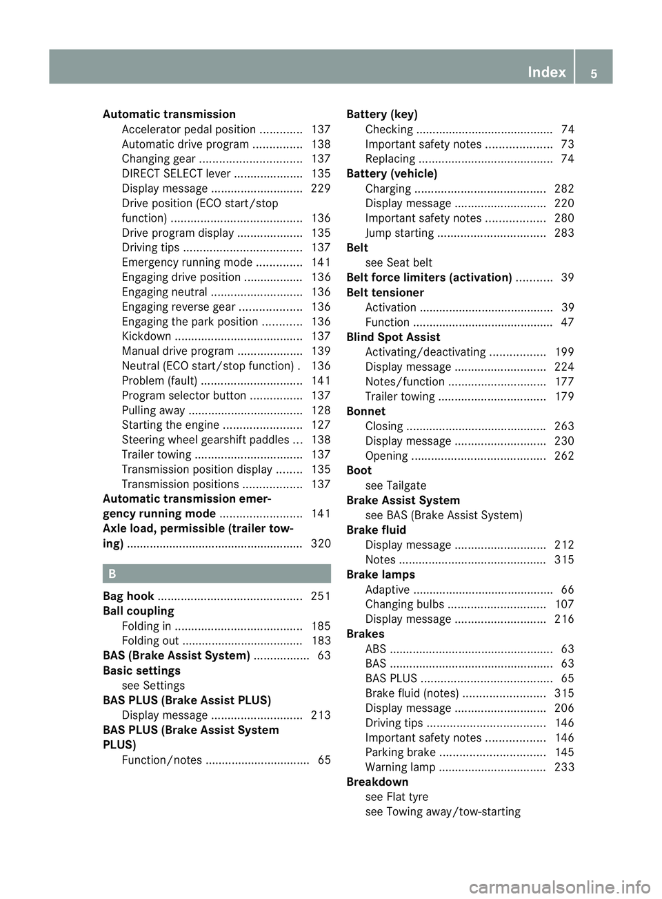
Automatic transmission
Accelerator pedal positio n............. 137
Automatic drive program ...............138
Changing gea r............................... 137
DIRECT SELECT leve r..................... 135
Display message ............................ 229
Drive position (ECO start/stop
function) ........................................ 136
Drive program displa y.................... 135
Driving tips .................................... 137
Emergency running mode ..............141
Engaging drive position .................. 136
Engaging neutra l............................ 136
Engaging revers egear ................... 136
Engaging the par kposition ............ 136
Kickdow n....................................... 137
Manual drive program ....................139
Neutral (ECO start/stop function) .136
Problem (fault) ............................... 141
Progra mselecto rbutton ................ 137
Pulling away ................................... 128
Starting the engine ........................127
Steering wheel gearshift paddle s... 138
Trailer towing ................................. 137
Transmissio nposition display ........135
Transmission positions ..................137
Automatic transmission emer-
gency running mode .........................141
Axle load, permissible (traile rtow-
ing) ...................................................... 320 B
Bag hook ............................................ 251
Ball coupling Folding in ....................................... 185
Folding out ..................................... 183
BAS (Brake Assist System) .................63
Basic settings see Settings
BAS PLUS (Brake Assist PLUS)
Display message ............................ 213
BAS PLUS (Brake Assist System
PLUS)
Function/notes ................................ 65 Battery (key)
Checking .......................................... 74
Important safety notes ....................73
Replacing ......................................... 74
Battery (vehicle)
Charging ........................................ 282
Display message ............................ 220
Important safety notes ..................280
Jump starting ................................. 283
Belt
see Seat belt
Belt force limiters (activation) ...........39
Belt tensioner Activation ......................................... 39
Function .......................................... .47
Blind Spo tAssist
Activating/deactivating .................199
Display message ............................ 224
Notes/function .............................. 177
Trailer towing ................................. 179
Bonnet
Closing .......................................... .263
Display message ............................ 230
Opening ......................................... 262
Boot
see Tailgate
Brake Assist System
see BAS (Brake Assist System)
Brake fluid
Display message ............................ 212
Notes ............................................. 315
Brake lamps
Adaptive .......................................... .66
Changin gbulbs .............................. 107
Display message ............................ 216
Brakes
ABS .................................................. 63
BAS .................................................. 63
BAS PLUS ........................................ 65
Brake fluid (notes) .........................315
Display message ............................ 206
Driving tips .................................... 146
Important safety notes ..................146
Parking brake ................................ 145
Warning lamp ................................. 233
Breakdown
see Flat tyre
see Towing away/tow-starting Index
5
Page 14 of 329
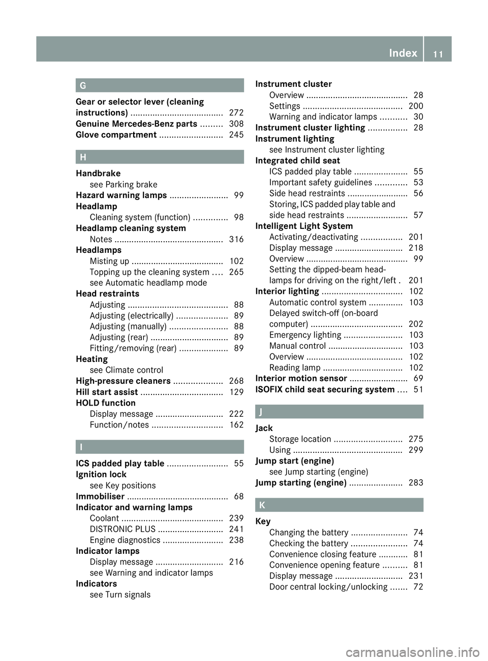
G
Gear or selectorl ever (cleaning
instructions) ...................................... 272
Genuine Mercedes-Benz parts .........308
Glove compartment ..........................245 H
Handbrake see Parking brake
Hazard warning lamps ........................99
Headlamp Cleaning system (function) ..............98
Headlamp cleaning system
Notes ............................................. 316
Headlamps
Misting up ...................................... 102
Topping up the cleaning system ....265
see Automatic headlamp mode
Head restraints
Adjusting ......................................... 88
Adjusting (electrically). ....................89
Adjusting (manually). .......................88
Adjusting (rear) ................................ 89
Fitting/removing (rear) ....................89
Heating
see Climate control
High-pressure cleaners ....................268
Hill start assist .................................. 129
HOLD function Display message ............................ 222
Function/notes ............................. 162 I
ICS padded play table .........................55
Ignition lock see Key positions
Immobiliser .......................................... 68
Indicator and warning lamps Coolant .......................................... 239
DISTRONI CPLUS ........................... 241
Engine diagnostics .........................238
Indicator lamps
Display message ............................ 216
see Warning and indicator lamps
Indicators
see Turn signals Instrument cluster
Overview .......................................... 28
Settings ......................................... 200
Warning and indicator lamps ...........30
Instrument cluster lighting ................28
Instrument lighting see Instrument cluster lighting
Integrated child seat
ICS padded pla ytable ...................... 55
Important safety guidelines .............53
Side hea drestraints ........................ .56
Storing, IC Spadded play table and
side head restraint s......................... 57
Intelligen tLight System
Activating/deactivatin g................. 201
Display message ............................ 218
Overview .......................................... 99
Setting the dipped-bea mhead-
lamps for driving on the right/left .201
Interior lighting ................................. 102
Automatic control system ..............103
Delayed switch-off (on-board
computer) ...................................... 202
Emergency lighting ........................103
Manual control ............................... 103
Overview ........................................ 102
Reading lamp ................................. 102
Interior motion sensor ........................69
ISOFIX child seat securing system ....51 J
Jack Storage location ............................ 275
Using ............................................. 299
Jump start (engine)
see Jump starting (engine)
Jump starting (engine) ......................283 K
Key Changing the battery .......................74
Checking the battery .......................74
Convenience closing feature ............81
Convenience opening feature ..........81
Display message ............................ 231
Door central locking/unlocking .......72 Index
11
Page 21 of 329
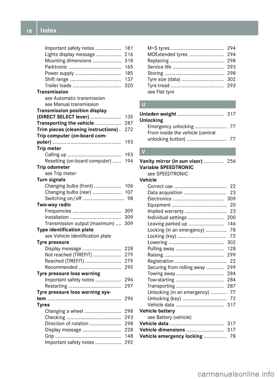
Important safety notes
..................181
Lights displa ymessage .................. 216
Mounting dimensions ....................318
Parktroni c...................................... 165
Power supply ................................. 185
Shift range ..................................... 137
Trailer loads ................................... 320
Transmission
see Automatic transmission
see Manual transmission
Transmission position display
(DIRECT SELECTl ever)...................... 135
Transporting the vehicle ..................287
Trim pieces (cleaning instructions) .272
Trip computer (on-board com-
puter) ................................................. .193
Trip meter Calling up ....................................... 193
Resetting (on-board computer) ......194
Trip odometer
see Trip meter
Turn signals
Changing bulbs (front) ...................106
Changing bulbs (rear) ....................107
Switching on/off .............................. 98
Two-way radio
Frequencies ................................... 309
Installatio n..................................... 309
Transmission output (maximum) .... 309
Type identification plate
see Vehicle identification plate
Tyre pressure
Display message ............................ 228
Not reached (TIREFIT) ....................279
Reached (TIREFIT) ..........................279
Recommended ............................... 295
Tyre pressure loss warning
Important safety notes ..................296
Restarting ...................................... 297
Tyre pressure loss warning sys-
tem ..................................................... 296
Tyres Changing awheel .......................... 298
Checking ........................................ 293
Direction of rotatio n...................... 298
Display message ............................ 228
Grip ................................................ 148
Important safety notes ..................292M+S tyres
...................................... 294
MOExtended tyres .........................294
Replacing ....................................... 298
Service life ..................................... 293
Storing ........................................... 298
Tyr esize (data) .............................. 302
Tyr etread ...................................... 293
see Flat tyre U
Unladen weight ................................. 317
Unlocking Emergency unlocking .......................77
From inside the vehicle (central
unlocking button) ............................. 77 V
Vanity mirror (in sun visor) ..............256
Variable SPEEDTRONIC see SPEEDTRONIC
Vehicle
Correct use ...................................... 22
Data acquisition ............................... 23
Electronics ..................................... 309
Equipment ....................................... 20
Implied warranty .............................. 23
Individua lsettings .......................... 200
Leaving parked up .........................146
Locking (in an emergency) ...............78
Locking (key )................................... 72
Lowering ........................................ 302
Pulling away ................................... 128
Raising ........................................... 299
Registration ..................................... 22
Securing from rolling away ............299
Towing away .................................. 284
Tow-starting ................................... 284
Transporting .................................. 287
Unlocking (in an emergency) ...........77
Unlocking (key )................................ 72
Vehicle data ................................... 317
Vehicle battery
see Battery (vehicle)
Vehicle data ....................................... 317
Vehicle dimensions ...........................317
Vehicle emergency locking ................7818
Index
Page 25 of 329
ponents and interference to your compo-
nents caused by other electrical/electronic
components can be largely prevented. Diagnostics connection
G
WARNING
If you connect equipment to the diagnostics
connection, it can affect the operation of the
vehicle systems. This can impair the operating
safety of your vehicle while driving. There is a
risk of accident.
Do not connect any equipment to the diag-
nostics connection. G
WARNING
Loose equipment or equipment cables that
are connected to the diagnostics connection
can obstruct the area around the pedals. The
equipment or the cables could get between
the pedals in the event of sudden braking or
acceleration. As a result, the movement of the
pedals may be impaired. There is a risk of
accident.
Do not attach any equipment or cables in the
driver footwell.
! If the engine is switched off and equip-
ment on the diagnostics connection is
used, the starter battery may discharge.
The diagnostics connection is only intended
for the connection of diagnostic equipment at
a qualified specialist workshop.
Connecting equipment to the diagnostics
connection can, for example, lead to emis-
sions monitoring information being reset.
This may lead to the vehicle failing to meet
the requirements of the nex temissions test
during the main inspection. Qualified specialist workshop
Aq ualified specialist workshop has the nec-
essary specialist knowledge, tools and quali-
fications to correctl ycarry out the work required on your vehicle
.This is especially the
case for work relevant to safety.
Observe the information in the Service Book-
let.
Always have the following work carried out at
a qualified specialist workshop:
R work relevant to safety
R service and maintenance work
R repair work
R alterations, installation work and modifica-
tions
R work on electronic components
Mercedes-Ben zrecommends that you use a
Mercedes-Benz Service Centre. Vehicle registration
Mercedes-Benz may ask its Service Centres
to carry out technical inspections on certain
vehicles to improve their quality or safety.
If you did not purchase your vehicle from an
authorised specialist dealer and your vehicle
has never been inspected at a Mercedes-
BenzS ervice Centre, it is possible that your
vehicle is not registered in your name with
Mercedes-Benz. Mercedes-Benz can only
infor myou about vehicle checks if it has your
registration data.
It is advisable to register your vehicle with a
Mercedes-Benz Service Centre.
InformM ercedes-Benza s soon as possible
abouta ny change in address or vehicle own-
ership. Correc
tuse G
WARNING
Various warning stickers are affixed to your
vehicle. Their purpose is to draw your atten-
tion, and the attention of others, to various
dangers. Therefore, do not remove any warn-
ing stickers unless the sticker clearly states
that you may do so. 22
Introduction
Page 76 of 329

Changing the settings of the locking
system
X To change the setting: press and hold
down the %and& buttons simulta-
neously for approximately six seconds until
the battery check lamp flashes twice
(Y page 74).
i If the setting of the locking system is
changed within the signal range of the vehi-
cle, pressing the &or% buttonlocks
or unlocks the vehicle.
The key now functions as follows:
X To unlock the driver's door: press the
% button once.
X To unlock centrally: press the%but-
ton twice.
X To lock centrally: press the&button.
You can change the setting of the locking
system in such a way that only the driver's
door and the fuel filler flap are unlocked. This
is useful if you frequently travel on your own. Restoring factory settings
X Press the %and& buttons simulta-
neously for approximately six seconds until
the battery check lamp flashes twice. Emergency key element
General notes If the vehicle can no longer be unlocked with
the key, use the emergency key element.
If you use the emergenc ykey element to
unlock and open the driver's door, the anti-
thef talarm system will be triggered
(Y page 68).
There are several ways to tur noff the alarm:
X Press the %or& button on the key.
or
X Insert the key into the ignition lock. If you unlock the vehicle using the emergency
key element, the fuel filler flap will not be
unlocked automatically.
X
To unlock the fuel filler flap: insert the
key into the ignition lock.
Removing the emergency key element X
Push release catch :in the direction of
the arrow and at the same time, remove
emergency key element ;from the key. Battery of the key
Important safety notes G
WARNING
Batteries are toxic and contain caustic sub-
stances. For this reason, keep batteries out of
the reach of children.
If a battery has been swallowed, visi tadoctor
immediately. H
Environmental note Batteries contain pollutants.
It is illegal to dispose of them
with the household rubbish.
They must be collected sep-
arately and disposed of in an
environmentally responsible
recycling system.
Dispose of batteries in an
environmentally responsible
manner. Take discharged
batteries to a qualified spe- Key
73Opening and closing
Z
Page 77 of 329

cialist workshop or to a col-
lection point for used batter-
ies.
Have the batteries changed at a qualified spe-
cialist workshop.
Checking the battery X
Press the &or% button.
The battery is working properly if battery
check lamp :lights up briefly.
The battery is discharged if battery check
lamp :does not light up briefly.
X Change the battery (Y page 74).
i If the key battery is checked within the
signal receptio nrange of the vehicle, press-
ing the &or% button:
R locks or
R unlocks the vehicle
i You can get a battery in any qualified spe-
cialist workshop.
Replacing the battery You require a CR 2025 3 V cell battery.
X
Take the emergency key elemen tout of the
key (Y page 73). X
Press emergency key element ;into the
opening in the key in the direction of the
arrow until battery tray cover :opens.
When doing so, do no thold cover :shut.
X Remove battery tray cover :. X
Repeatedly tap the key against your palm
until battery =falls out.
X Insert the new battery with the positive ter-
minal facing upwards. Use a lint-free cloth
to do so.
X Make sure that the surface of the battery is
free from lint, grease and all other forms of
contamination.
X Insert the front tabs of battery tray
cover :and then press to close it.
X Insert the emergency key element into the
key.
X Check the function of all key buttons on the
vehicle. 74
KeyOpening and closing
Page 78 of 329
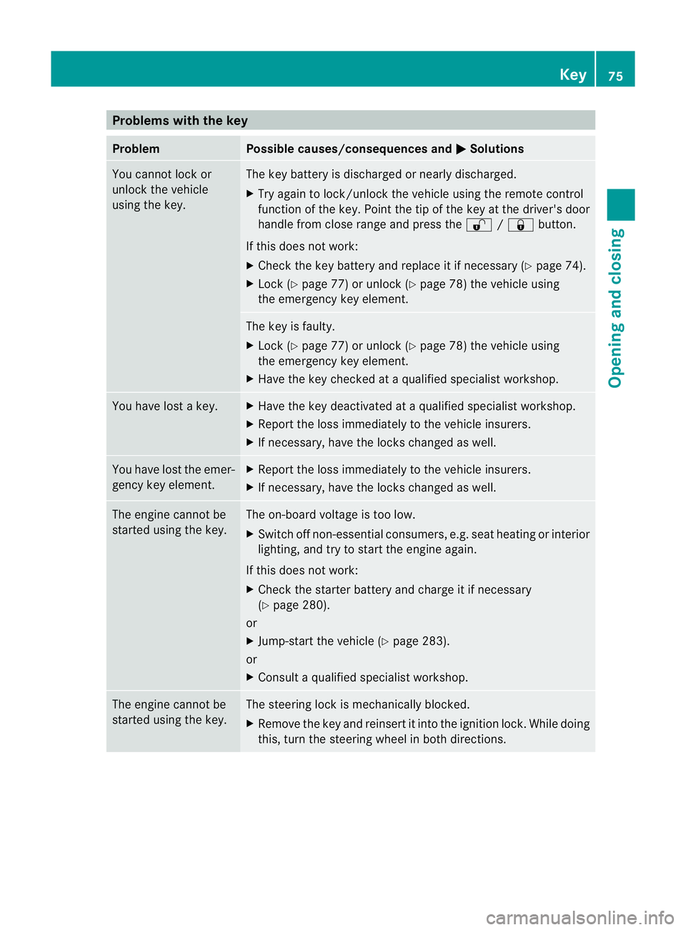
Problems with the key
Problem Possible causes/consequences and
M Solutions
You cannot lock or
unlock the vehicle
using the key. The key battery is discharged or nearly discharged.
X
Try again to lock/unlock the vehicle using the remote control
function of the key. Point the tip of the key at the driver's door
handle from close range and press the %/& button.
If this does not work:
X Check the key battery and replace it if necessary (Y page 74).
X Lock (Y page 77) or unlock (Y page 78) the vehicle using
the emergency key element. The key is faulty.
X
Lock (Y page 77) or unlock (Y page 78) the vehicle using
the emergency key element.
X Have the key checked at a qualified specialist workshop. You have lost a key. X
Have the key deactivated at a qualified specialist workshop.
X Report the loss immediately to the vehicle insurers.
X If necessary, have the locks changed as well. You have lost the emer-
gency key element. X
Report the loss immediately to the vehicle insurers.
X If necessary, have the locks changed as well. The engine cannot be
started using the key. The on-board voltage is too low.
X
Switch off non-essential consumers, e.g. seat heating or interior
lighting, and try to start the engine again.
If this does not work:
X Check the starter battery and charge it if necessary
(Y page 280).
or
X Jump-start the vehicle (Y page 283).
or
X Consult a qualified specialist workshop. The engine cannot be
started using the key. The steering lock is mechanically blocked.
X
Remove the key and reinsert it into the ignition lock. While doing
this, turn the steering wheel in both directions. Key
75Opening and closing Z
Page 93 of 329
X
Press release catch :and pull the head
restraint out of the guides.
X To refit: insert the head restraint so that
the notches on the bar are on the left when
viewed in the direction of travel.
X Push the head restraint down until you hear
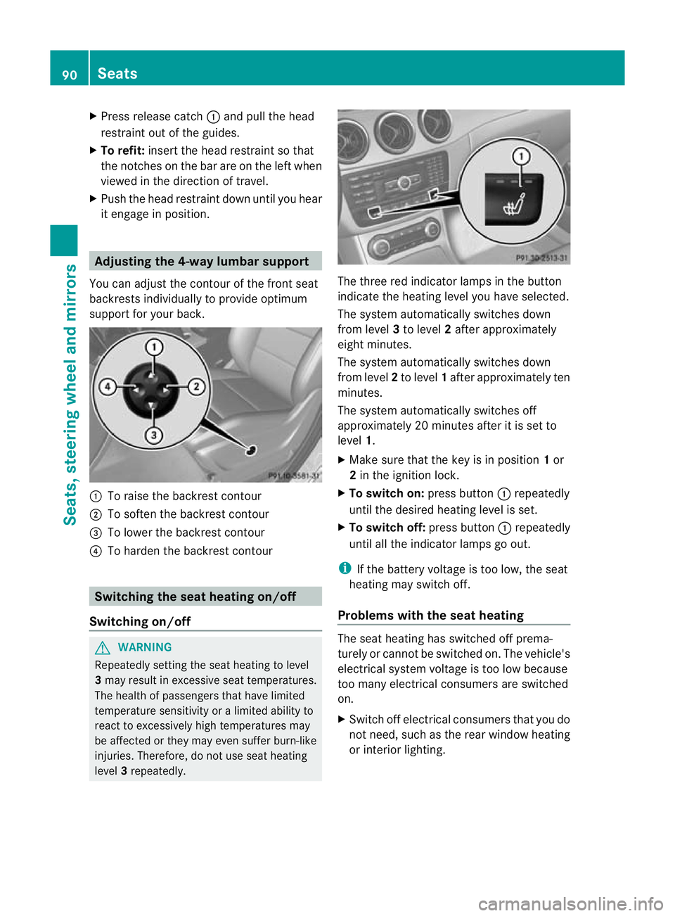
it engage in position. Adjusting the 4-way lumbar support
You can adjust the contour of the front seat
backrests individually to provide optimum
support for your back. :
To raise the backrest contour
; To soften the backrest contour
= To lower the backrest contour
? To harden the backrest contour Switching the seat heating on/off
Switching on/off G
WARNING
Repeatedly setting the seat heating to level
3 may result in excessive seat temperatures.
The health of passengers that have limited
temperature sensitivity or a limited ability to
react to excessively high temperatures may
be affected or they may even suffer burn-like
injuries. Therefore, do not use seat heating
level 3repeatedly. The three red indicator lamps in the button
indicate the heating level you have selected.
The system automatically switches down
from level
3to level 2after approximately
eight minutes.
The system automatically switches down
from level 2to level 1after approximately ten
minutes.
The system automatically switches off
approximately 20 minutes after it is set to
level 1.
X Make sure that the key is in position 1or
2 in the ignition lock.
X To switch on: press button:repeatedly
until the desired heating level is set.
X To switch off: press button:repeatedly
until all the indicator lamps go out.
i If the battery voltage is too low, the seat
heating may switch off.
Problems with the seat heating The seat heating has switched off prema-
turely or cannot be switched on. The vehicle's
electrical system voltage is too low because
too many electrical consumers are switched
on.
X Switch off electrical consumers that you do
not need, such as the rear window heating
or interior lighting. 90
SeatsSeats, steering wheel and mirrors
Page 95 of 329
X
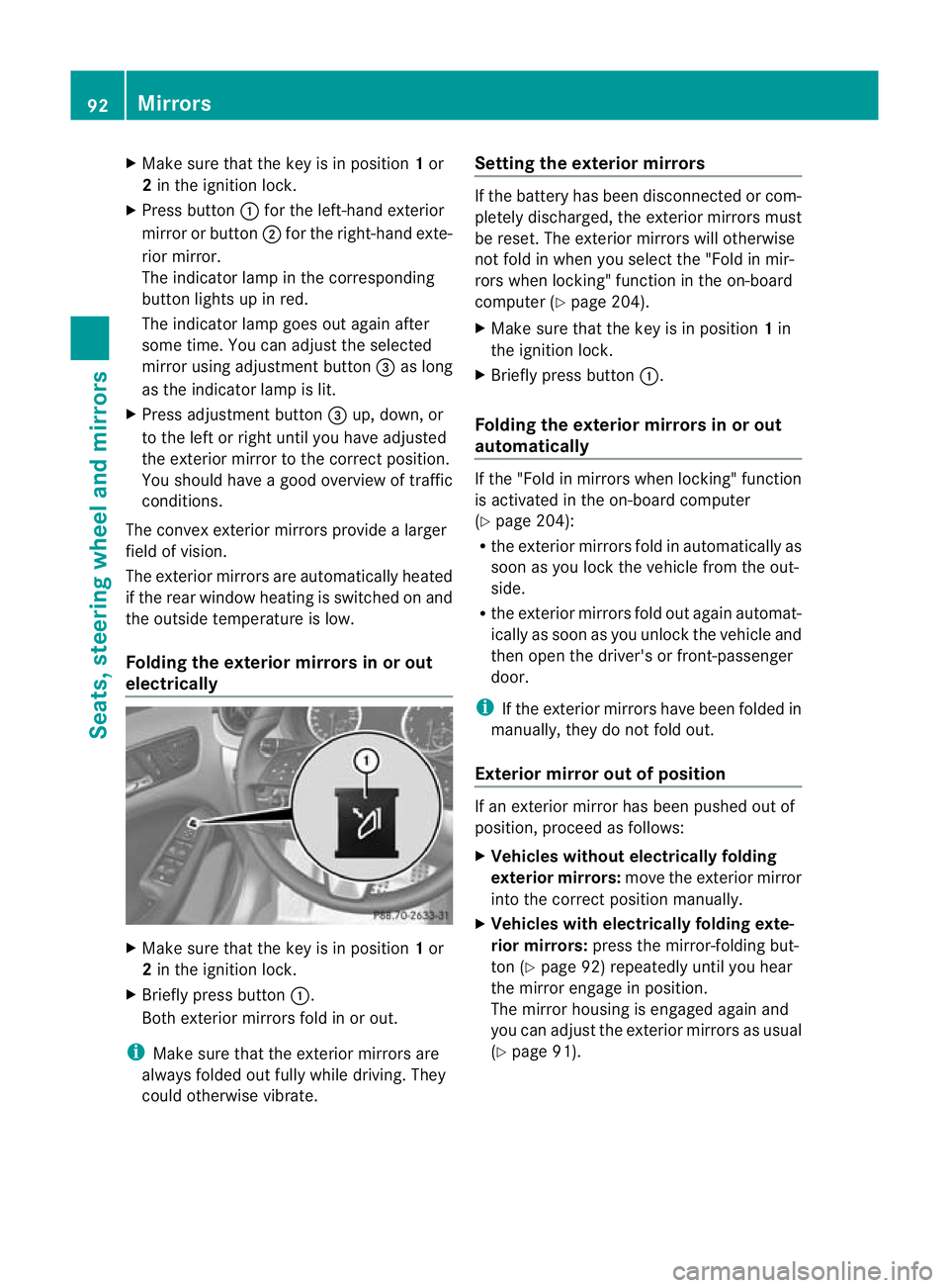
Make sure that the key is in position 1or
2 in the ignition lock.
X Press button :for the left-hand exterior
mirror or button ;for the right-hand exte-
rior mirror.
The indicator lamp in the corresponding
button lights up in red.
The indicator lamp goes out again after
some time. You can adjust the selected
mirror using adjustment button =as long
as the indicator lamp is lit.
X Press adjustment button =up, down, or
to the left or right until you have adjusted
the exterior mirror to the correct position.
You should have a good overview of traffic
conditions.
The convex exterior mirrors provide a larger
field of vision.
The exterior mirrors are automatically heated
if the rear window heating is switched on and
the outside temperature is low.
Folding the exterior mirrors in or out
electrically X
Make sure that the key is in position 1or
2 in the ignition lock.
X Briefly press button :.
Both exterior mirrors fold in or out.
i Make sure that the exterior mirrors are
always folded out fully while driving. They
could otherwise vibrate. Setting the exterior mirrors If the battery has been disconnected or com-
pletely discharged, the exterior mirrors must
be reset. The exterior mirrors will otherwise
not fold in when you select the "Fold in mir-
rors when locking" function in the on-board
computer (Y
page 204).
X Make sure that the key is in position 1in
the ignition lock.
X Briefly press button :.
Folding the exterior mirrors in or out
automatically If the "Fold in mirrors when locking" function
is activated in the on-board computer
(Y
page 204):
R the exterior mirrors fold in automatically as
soon as you lock the vehicle from the out-
side.
R the exterior mirrors fold out again automat-
ically as soon as you unlock the vehicle and
then open the driver's or front-passenger
door.
i If the exterior mirrors have been folded in
manually, they do not fold out.
Exterior mirror out of position If an exterior mirror has been pushed out of
position, proceed as follows:
X
Vehicles without electrically folding
exterior mirrors: move the exterior mirror
into the correct position manually.
X Vehicles with electrically folding exte-
rior mirrors: press the mirror-folding but-
ton (Y page 92) repeatedly until you hear
the mirror engage in position.
The mirror housing is engaged again and
you can adjust the exterior mirrors as usual
(Y page 91). 92
MirrorsSeats, steering wheel and mirrors
Page 99 of 329
Useful information
i This Owner's Manual describes all models
and all standard and optional equipment
available to your vehicle at the time of pub-
lication of the Owner's Manual. Country-
specific deviations are possible. Please
note that your vehicle may not be equipped
with all features described. This also
applies to safety-relevan tsystems and
functions.
i Please read the information on qualified
specialist workshops (Y page 22).Exterior lighting
Important safety notes
Fo rreasons of safety, Mercedes-Benzr ecom-
mends that you drive with the lights switched
on even during the daytime. In some coun-
tries, operation of the headlamps varies due
to legal requirements and self-imposed obli-
gations. Notes on driving abroad
To convert to symmetrical dipped beam
when driving abroad: switch the headlamps
to symmetrical dipped beam in countries in
which traffic drives on the opposite side of the
road to the country where the vehicle is reg-
istered. This prevents glare to oncoming traf-
fic. When using symmetrical lights, the edge
of the carriageway is not lit as widely and as
far ahead as normal.
Convert the headlamps as close to the border
as possible before driving in these countries
(Y page 201).
Convert to asymmetrical dipped beam
after returning: convert the headlamps back
to asymmetrical dipped beam as soon as pos-
sible after crossing the border when returning
(Y page 201). If the headlamps are converted to symmetri-
cal dipped beam, the "motorway mode" and
"extended range foglamps" functions (Intelli-
gent Light System) are not available. Light switch
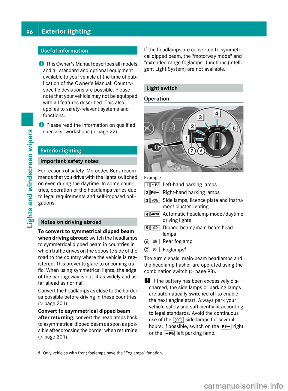
Operation Example
1W
Left-hand parking lamps
2X Right-hand parking lamps
3T Side lamps, licence plate and instru-
ment cluster lighting
4Ã Automatic headlamp mode/daytime
driving lights
5L Dipped-beam/main-beam head-
lamps
BR Rear foglamp
CN Foglamps 4
The turn signals, main-beam headlamps and
the headlamp flasher are operated using the
combination switch (Y page 98).
! If the battery has been excessively dis-
charged, the side lamps or parking lamps
are automatically switched off to enable
the nexte ngine start. Always park your
vehicle safely and sufficiently li taccording
to legal standards. Avoid the continuous
use of the Tside lamps for several
hours. If possible, switch on the Xright
or the Wleft parking lamp.
4 Only vehicles with front foglamps have the "Foglamps "function. 96
Exterior lightingLights and windscreen wipers