bonnet MERCEDES-BENZ B-CLASS HATCHBACK 2014 Owners Manual
[x] Cancel search | Manufacturer: MERCEDES-BENZ, Model Year: 2014, Model line: B-CLASS HATCHBACK, Model: MERCEDES-BENZ B-CLASS HATCHBACK 2014Pages: 405, PDF Size: 12.24 MB
Page 8 of 405
Switching off the alarm .................... 80
ATTENTION ASSIST
Activating/deactivating ................. 244
Display message ............................ 271
Function/note s............................. 216
Audio menu (on-board computer) .... 239
AUTO lights
Display message ............................ 268
see Lights
Automatic engine start (ECO start/
stop function) .................................... 165
Automatic engine switch-off (ECO
start/stop function) .......................... 164
Automatic front-passenger front
airbag deactivation
Display message ............................ 264
Automatic front-passenger front
airbag deactivation system
Operation ......................................... 50
Problems ......................................... 54
System self-test ............................... 52
Automatic headlamp mode .............. 123
Automatic transmission
Accelerator pedal position ............. 173
Automatic drive program ............... 174
Changing gear ............................... 173
DIRECT SELECT lever ..................... 170
Drive program display .................... 170
Driving tips .................................... 173
Emergency running mode .............. 177
Engaging drive position .................. 172
Engaging neutral ............................ 171
Engaging park position automati-
cally ............................................... 171
Engaging reverse gear ................... 171
Engaging the park position ............ 170
Holding the vehicle stationary on
uphill gradients .............................. 173
Kickdown ....................................... 173
Manual drive progra m.................... 175
Overview ........................................ 169
Problem (fault) ............................... 177
Program selector button ................ 174
Pulling away ................................... 162
Starting the engine ........................ 161
Steering wheel gearshift paddle s... 174
Trailer towing ................................. 174
Transmission position display ........ 170 Transmission positions .................. 172
Automatic transmission emer-
gency running mode ......................... 177
Auxiliary heating
Activating/deactivating ................. 151
Activating/deactivating (on the
centre console ).............................. 151
Display message ............................ 282
Remote control .............................. 151
Setting ........................................... 248
Auxiliary heating/ventilation
Important safety notes .................. 150
Problem (display message) ............ 155
Setting the departure time ............. 153
Auxiliary ventilation
Activating/deactivating ................. 151
Activating/deactivating (on the
centre console ).............................. 151
Remote control .............................. 151
Axle load, permissible (trailer tow-
ing) ...................................................... 396 B
Bag hook ............................................ 305
Ball coupling
Folding in ....................................... 228
Folding ou t..................................... 226
BAS (Brake Assist System) ................. 74
Battery (key)
Checking .......................................... 90
Important safety notes .................... 89
Replacing ......................................... 90
Battery (vehicle)
Charging ........................................ 341
Display message ............................ 269
Important safety notes .................. 338
Jump starting ................................. 342
Belt tensioner
Activation ......................................... 54
Blind Spot Assist
Activating/deactivating (on-
board computer) ............................ 245
Display message ............................ 272
Notes/function .............................. 221
Trailer towing ................................. 222
Bonnet
Closing ........................................... 319 Index
5
Page 31 of 405
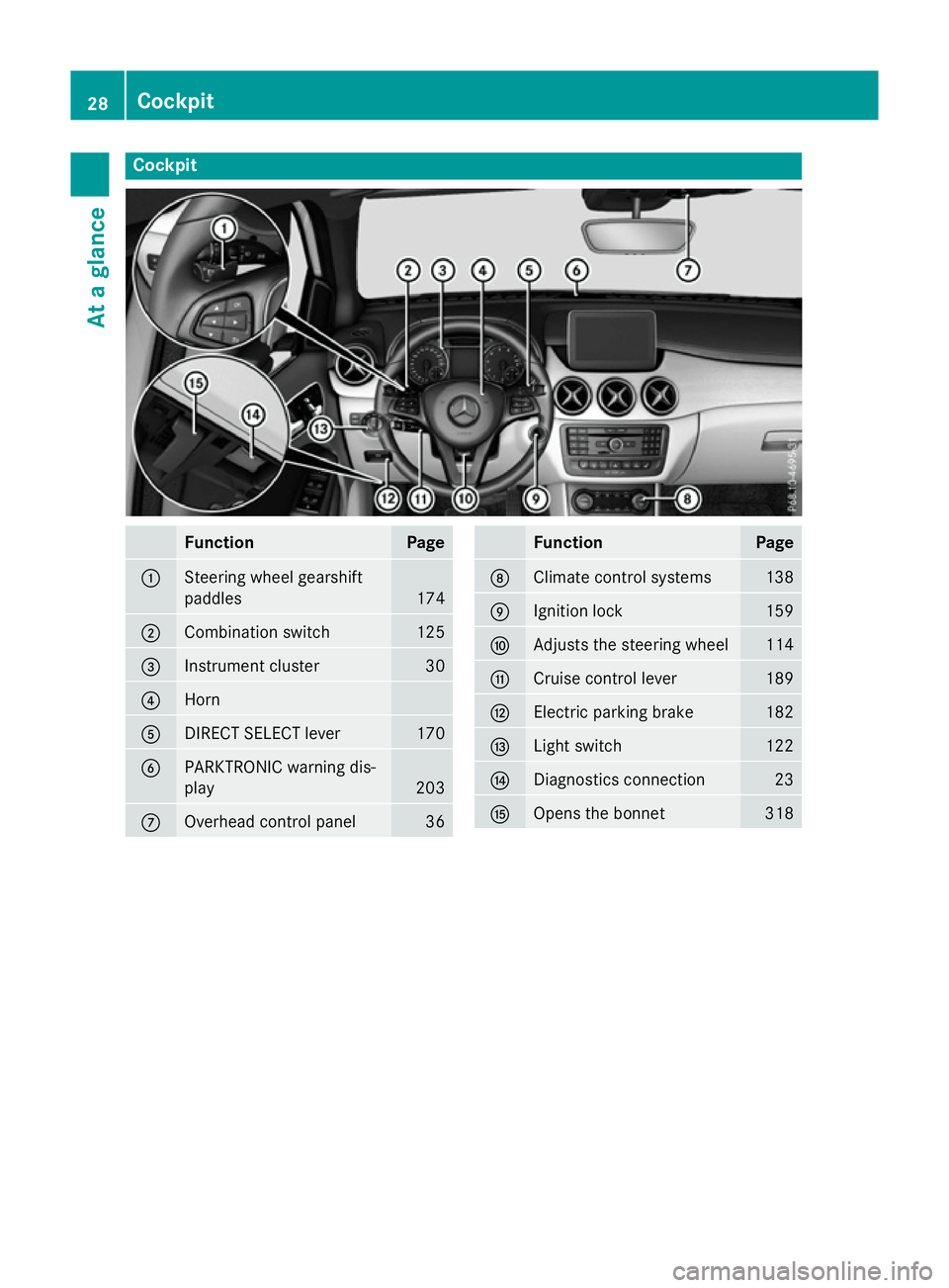
Cockpit
Function Page
:
Steering wheel gearshift
paddles
174
;
Combination switch 125
=
Instrument cluster 30
?
Horn
A
DIRECT SELECT lever 170
B
PARKTRONIC warning dis-
play
203
C
Overhead control panel 36 Function Page
D
Climate control systems 138
E
Ignition lock 159
F
Adjusts the steering wheel 114
G
Cruise control lever 189
H
Electric parking brake 182
I
Light switch 122
J
Diagnostics connection 23
K
Opens the bonnet 31828
CockpitAt a glance
Page 32 of 405
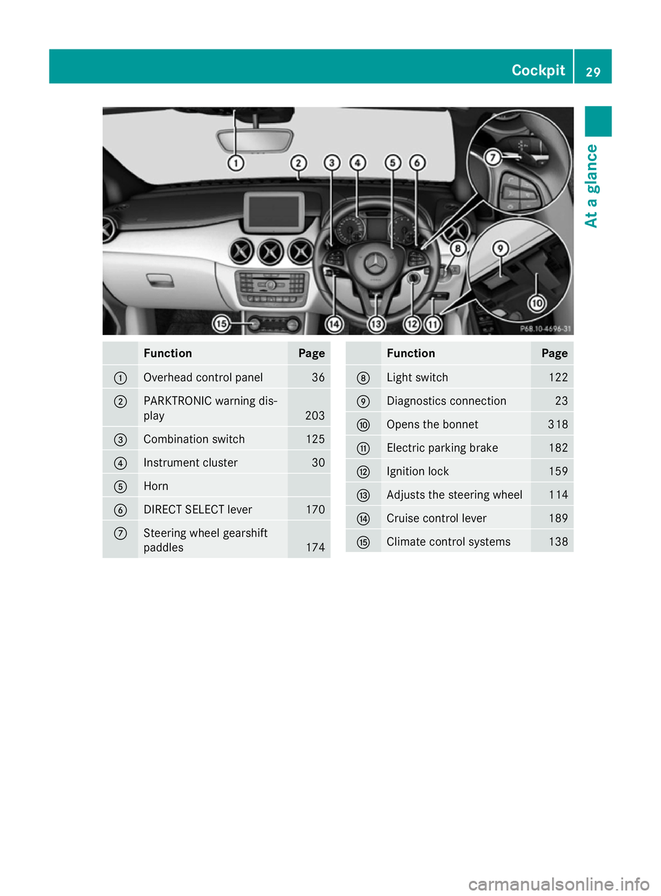
Function Page
:
Overhead control panel 36
;
PARKTRONIC warning dis-
play 203
=
Combination switch 125
?
Instrument cluster 30
A
Horn
B
DIRECT SELECT lever 170
C
Steering wheel gearshift
paddles
174 Function Page
D
Light switch 122
E
Diagnostics connection 23
F
Opens the bonnet 318
G
Electric parking brake 182
H
Ignition lock 159
I
Adjusts the steering wheel 114
J
Cruise control lever 189
K
Climate control systems 138Cockpit
29At a glance
Page 83 of 405
This steering support is provided in particular
if:
R both right wheels or both left wheels are on
a wet or slippery road surface when you
brake
R the vehicle starts to skid
Important safety notes i
Observe the "Important safety notes" sec-
tion (Y page 73).
No steering support is provided from STEER
CONTROL, if:
R ESP ®
is malfunctioning
R the steering is faulty
If ESP ®
is malfunctioning, you will be assisted
further by the electrical power steering. Protection against theft
Immobiliser
The immobiliser prevents your vehicle from
being started without the correct key.
X To activate with the key: remove the key
from the ignition lock.
X To activate with KEYLESS-GO start func-
tion or KEYLESS-GO: switch the ignition
off and open the driver's door.
X To deactivate: switch on the ignition.
When leaving the vehicle, always take the key with you and lock the vehicle. Anyone can
start the engine if a valid key has been left
inside the vehicle.
i The immobiliser is always deactivated
when you start the engine. ATA (Anti-Theft Alarm system)
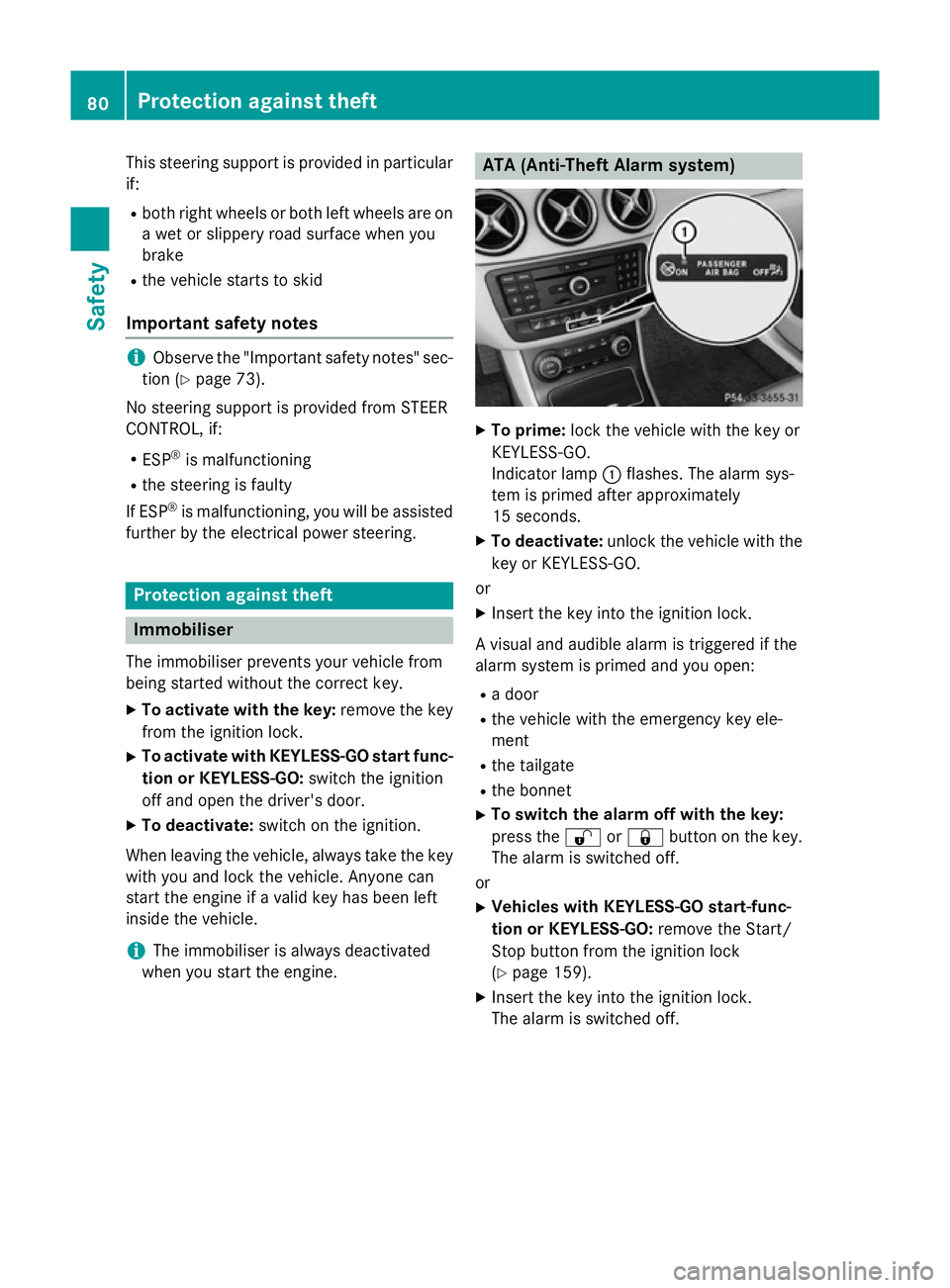
X
To prime: lock the vehicle with the key or
KEYLESS-GO.
Indicator lamp :flashes. The alarm sys-
tem is primed after approximately
15 seconds.
X To deactivate: unlock the vehicle with the
key or KEYLESS-GO.
or X Insert the key into the ignition lock.
A visual and audible alarm is triggered if the
alarm system is primed and you open: R a door
R the vehicle with the emergency key ele-
ment
R the tailgate
R the bonnet
X To switch the alarm off with the key:
press the %or& button on the key.
The alarm is switched off.
or X Vehicles with KEYLESS-GO start-func-
tion or KEYLESS-GO: remove the Start/
Stop button from the ignition lock
(Y page 159).
X Insert the key into the ignition lock.
The alarm is switched off. 80
Protection against theftSafety
Page 133 of 405
X
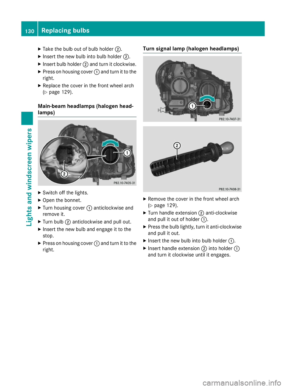
Take the bulb out of bulb holder ;.
X Insert the new bulb into bulb holder ;.
X Insert bulb holder ;and turn it clockwise.
X Press on housing cover :and turn it to the
right.
X Replace the cover in the front wheel arch
(Y page 129).
Main-beam headlamps (halogen head-
lamps) X
Switch off the lights.
X Open the bonnet.
X Turn housing cover :anticlockwise and
remove it.
X Turn bulb ;anticlockwise and pull out.
X Insert the new bulb and engage it to the
stop.
X Press on housing cover :and turn it to the
right. Turn signal lamp (halogen headlamps)
X
Remove the cover in the front wheel arch
(Y page 129).
X Turn handle extension ;anti-clockwise
and pull it out of holder :.
X Press the bulb lightly, turn it anti-clockwise
and pull it out.
X Insert the new bulb into bulb holder :.
X Insert handle extension ;into holder :
and turn it clockwise until it engages. 130
Replacing bulbsLights and windscreen wipers
Page 137 of 405
Switching the rear window wiper on/
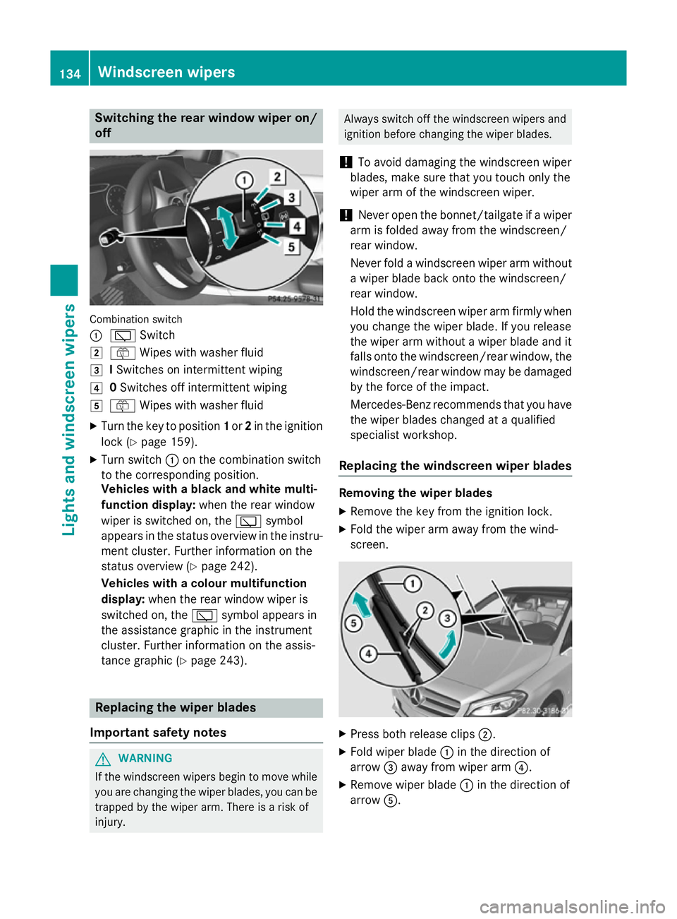
off Combination switch
:
è Switch
2 ô Wipes with washer fluid
3 ISwitches on intermittent wiping
4 0Switches off intermittent wiping
5 ô Wipes with washer fluid
X Turn the key to position 1or 2in the ignition
lock (Y page 159).
X Turn switch :on the combination switch
to the corresponding position.
Vehicles with a black and white multi-
function display: when the rear window
wiper is switched on, the èsymbol
appears in the status overview in the instru- ment cluster. Further information on the
status overview (Y page 242).
Vehicles with a colour multifunction
display: when the rear window wiper is
switched on, the èsymbol appears in
the assistance graphic in the instrument
cluster. Further information on the assis-
tance graphic (Y page 243). Replacing the wiper blades
Important safety notes G
WARNING
If the windscreen wipers begin to move while
you are changing the wiper blades, you can be trapped by the wiper arm. There is a risk of
injury. Always switch off the windscreen wipers and
ignition before changing the wiper blades.
! To avoid damaging the windscreen wiper
blades, make sure that you touch only the
wiper arm of the windscreen wiper.
! Never open the bonnet/tailgate if a wiper
arm is folded away from the windscreen/
rear window.
Never fold a windscreen wiper arm without a wiper blade back onto the windscreen/
rear window.
Hold the windscreen wiper arm firmly when
you change the wiper blade. If you release
the wiper arm without a wiper blade and it
falls onto the windscreen/rear window, the windscreen/rear window may be damaged
by the force of the impact.
Mercedes-Benz recommends that you have the wiper blades changed at a qualified
specialist workshop.
Replacing the windscreen wiper blades Removing the wiper blades
X Remove the key from the ignition lock.
X Fold the wiper arm away from the wind-
screen. X
Press both release clips ;.
X Fold wiper blade :in the direction of
arrow =away from wiper arm ?.
X Remove wiper blade :in the direction of
arrow A. 134
Windscreen wipersLights and windscreen wipers
Page 158 of 405
Problems with the auxiliary heating/ventilation
Display messages
Possible causes/consequences and
M
MSolutions FAIL¨ The signal transmission between the transmitter and the vehicle is
faulty.
X Change your position in relation to the vehicle, moving closer if
necessary.
X Make another attempt to switch the auxiliary heating/ventila-
tion on or off using the remote control. FAIL The auxiliary heating cannot be switched on or has switched itself
off.
The starter battery is not sufficiently charged.
X Charge the starter battery.
X Make another attempt to switch on the auxiliary heating/venti-
lation using the remote control. The auxiliary heating cannot be switched on or has switched itself
off.
The fuel tank content is below the reserve fuel level.
X Refuel at the nearest filling station.
X Make another attempt to switch on the auxiliary heating using
the remote control. The auxiliary heating/ventilation cannot be switched on or has
switched itself off.
The auxiliary heating/ventilation is malfunctioning.
X Have the auxiliary heating/ventilation checked at a qualified
specialist workshop. Air vents
Important safety notes
G
WARNING
Very hot or very cold air can flow from the air vents. This could result in burns or frostbite in the immediate vicinity of the air vents. There
is a risk of injury.
Make sure that all vehicle occupants always
maintain a sufficient distance to the air out-
lets. If necessary, redirect the airflow to
another area of the vehicle interior. In order to ensure the direct flow of fresh air
through the air vents into the vehicle interior,
please observe the following notes:
R keep the air inlet between the windscreen
and the bonnet free of blockages, such as
ice, snow or leaves
R never cover the vents or ventilation grilles
in the vehicle interior
i Move the adjusters for the air vents ver-
tically or horizontally, to set the direction of the airflow. Air vents
155Climate control Z
Page 167 of 405
Important safety notes
G
WARNING
If the engine is switched off automatically and you exit the vehicle, the engine is restarted
automatically. The vehicle may begin moving. There is a risk of accident and injury.
If you wish to exit the vehicle, always turn off
the ignition and secure the vehicle against
rolling away.
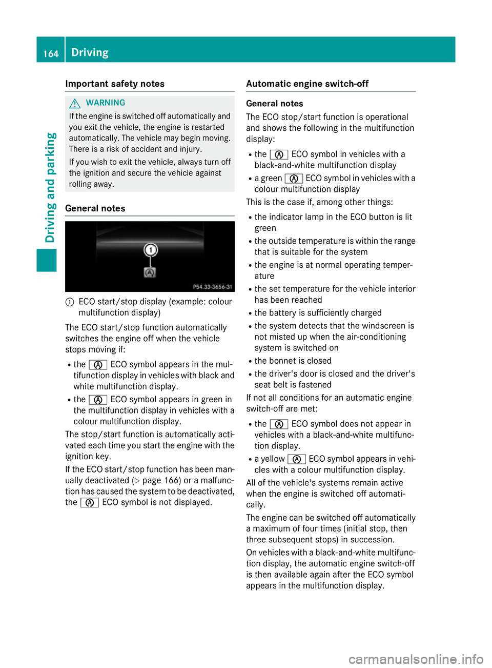
General notes :
ECO start/stop display (example: colour
multifunction display)
The ECO start/stop function automatically
switches the engine off when the vehicle
stops moving if:
R the è ECO symbol appears in the mul-
tifunction display in vehicles with black and white multifunction display.
R the è ECO symbol appears in green in
the multifunction display in vehicles with a
colour multifunction display.
The stop/start function is automatically acti-
vated each time you start the engine with the ignition key.
If the ECO start/stop function has been man- ually deactivated (Y page 166) or a malfunc-
tion has caused the system to be deactivated, the è ECO symbol is not displayed. Automatic engine switch-off General notes
The ECO stop/start function is operational
and shows the following in the multifunction
display:
R the è ECO symbol in vehicles with a
black-and-white multifunction display
R a green èECO symbol in vehicles with a
colour multifunction display
This is the case if, among other things:
R the indicator lamp in the ECO button is lit
green
R the outside temperature is within the range
that is suitable for the system
R the engine is at normal operating temper-
ature
R the set temperature for the vehicle interior
has been reached
R the battery is sufficiently charged
R the system detects that the windscreen is
not misted up when the air-conditioning
system is switched on
R the bonnet is closed
R the driver's door is closed and the driver's
seat belt is fastened
If not all conditions for an automatic engine
switch-off are met:
R the è ECO symbol does not appear in
vehicles with a black-and-white multifunc-
tion display.
R a yellow èECO symbol appears in vehi-
cles with a colour multifunction display.
All of the vehicle's systems remain active
when the engine is switched off automati-
cally.
The engine can be switched off automatically
a maximum of four times (initial stop, then
three subsequent stops) in succession.
On vehicles with a black-and-white multifunc- tion display, the automatic engine switch-off
is then available again after the ECO symbol
appears in the multifunction display. 164
DrivingDriving and pa
rking
Page 235 of 405
Useful information
i This Owner's Manual describes all mod-
els, series and optional equipment for your
vehicle that were available at the time of
going to press. National variations are pos- sible. Note that your vehicle may not be
equipped with all of the functions descri-
bed. This is also the case for systems and
functions relevant to safety.
i Read the information on qualified special-
ist workshops: (Y page 24). Important safety notes
G
WARNING
Operating the integrated information systems and communications equipment in the vehicle
while driving will distract you from traffic con-
ditions. You could then lose control of the
vehicle. There is a risk of an accident.
Only operate these devices if road traffic con-
ditions permit. If you are unsure about the
surrounding conditions, pull over to a safe
location and make entries only while the vehi-
cle is stationary.
You must observe the legal requirements for
the country in which you are currently driving when operating the on-board computer. G
WARNING
If the instrument cluster has failed or mal-
functioned, you may not recognise function
restrictions relevant to safety. The operating
safety of your vehicle may be impaired. There is a risk of an accident.
Drive on carefully. Have the vehicle checked
at a qualified specialist workshop immedi-
ately.
The on-board computer only shows messages
or warnings from certain systems in the mul- tifunction display. You should therefore make
sure your vehicle is operating safely at all
times. If the operating safety of your vehicle is
impaired, park the vehicle safely as soon as
possible. Contact a qualified specialist work-
shop.
For an overview, see the instrument panel
illustration (Y
page 30). Displays and operation
Instrument cluster lighting
The light sensor in the instrument cluster
automatically controls the brightness of the
multifunction display. In daylight, the displays
in the instrument cluster are not illuminated.
The lighting in the instrument cluster, in the
displays and the controls in the vehicle inte-
rior can be adjusted using the brightness con-
trol knob.
The brightness control knob is located on the bottom left of the instrument cluster
(Y page 30).
X Turn the brightness control knob clockwise
or anti-clockwise.
If the light switch is set to Ã,Tor
L, the brightness is dependent upon
the brightness of the ambient light. Coolant temperature gauge
G
WARNING
If you open the bonnet while the engine is
overheating or while there is a fire in the
engine compartment, you could come into
contact with hot gases or other leaking ser-
vice products. There is a danger of injury.
Allow an overheating engine to cool down
before opening the bonnet. If there is a fire in the engine compartment, leave the bonnet
closed and notify the fire brigade.
The coolant temperature gauge is in the
instrument cluster on the right-hand side
(Y page 30). 232
Displays and operationOn-board computer and displays
Page 272 of 405
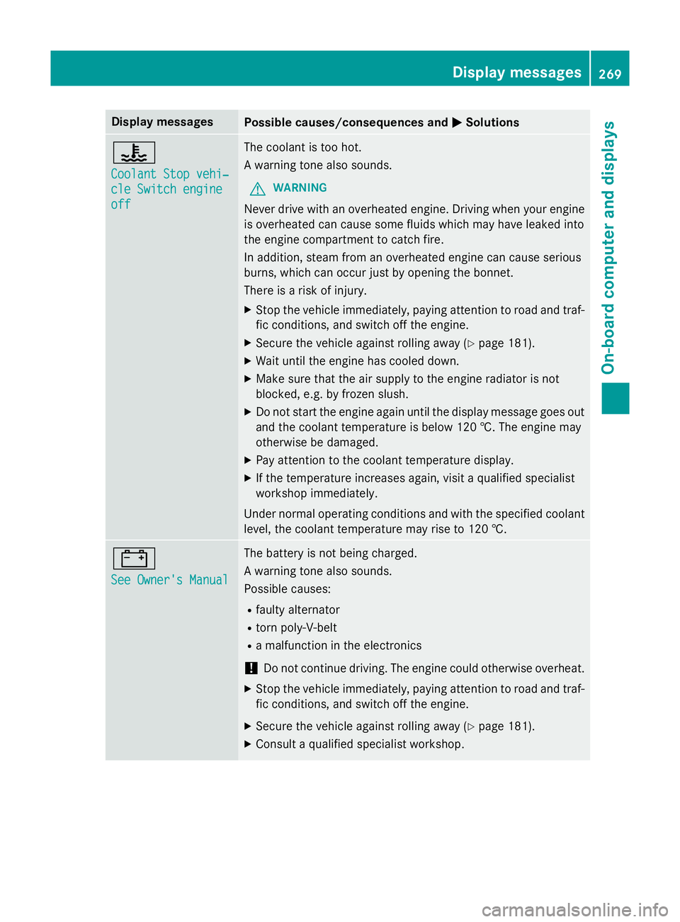
Display messages
Possible causes/consequences and
M
MSolutions ?
Coolant Stop vehi‐ Coolant Stop vehi‐
cle Switch engine cle Switch engine
off off The coolant is too hot.
A warning tone also sounds.
G WARNING
Never drive with an overheated engine. Driving when your engine is overheated can cause some fluids which may have leaked into
the engine compartment to catch fire.
In addition, steam from an overheated engine can cause serious
burns, which can occur just by opening the bonnet.
There is a risk of injury.
X Stop the vehicle immediately, paying attention to road and traf-
fic conditions, and switch off the engine.
X Secure the vehicle against rolling away (Y page 181).
X Wait until the engine has cooled down.
X Make sure that the air supply to the engine radiator is not
blocked, e.g. by frozen slush.
X Do not start the engine again until the display message goes out
and the coolant temperature is below 120 †. The engine may
otherwise be damaged.
X Pay attention to the coolant temperature display.
X If the temperature increases again, visit a qualified specialist
workshop immediately.
Under normal operating conditions and with the specified coolant level, the coolant temperature may rise to 120 †. #
See Owner's Manual See Owner's Manual The battery is not being charged.
A warning tone also sounds.
Possible causes:
R faulty alternator
R torn poly-V-belt
R a malfunction in the electronics
! Do not continue driving. The engine could otherwise overheat.
X Stop the vehicle immediately, paying attention to road and traf-
fic conditions, and switch off the engine.
X Secure the vehicle against rolling away (Y page 181).
X Consult a qualified specialist workshop. Display
messages
269On-board computer and displays Z