engine MERCEDES-BENZ B-CLASS HATCHBACK 2015 User Guide
[x] Cancel search | Manufacturer: MERCEDES-BENZ, Model Year: 2015, Model line: B-CLASS HATCHBACK, Model: MERCEDES-BENZ B-CLASS HATCHBACK 2015Pages: 293, PDF Size: 10.83 MB
Page 96 of 293
Mirrors
Rear-view mirror
X
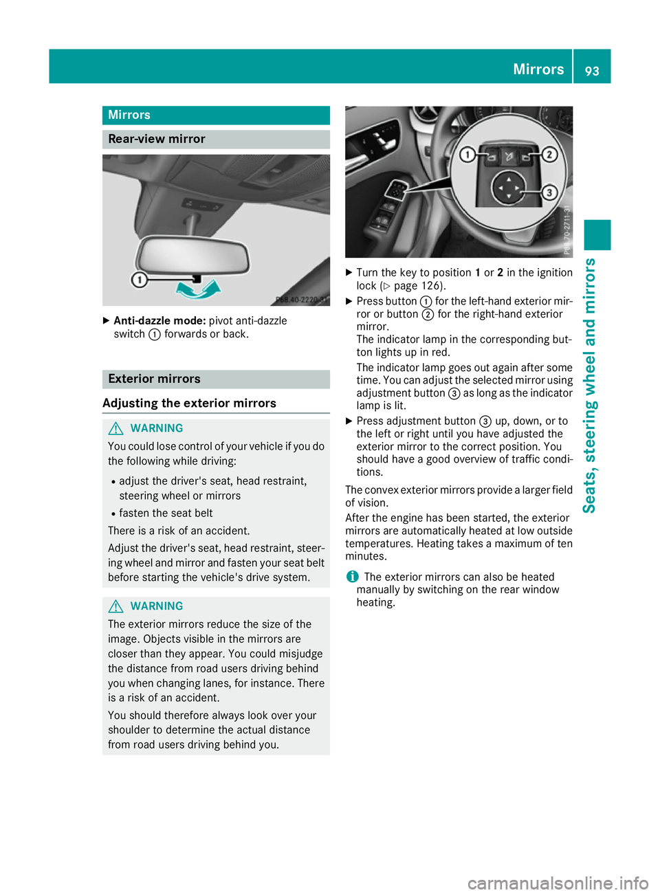
Anti-dazzle mode: pivot anti-dazzle
switch :forwards or back. Exterior mirrors
Adjusting the exterior mirrors G
WARNING
You could lose control of your vehicle if you do the following while driving:
R adjust the driver's seat, head restraint,
steering wheel or mirrors
R fasten the seat belt
There is a risk of an accident.
Adjust the driver's seat, head restraint, steer-
ing wheel and mirror and fasten your seat belt before starting the vehicle's drive system. G
WARNING
The exterior mirrors reduce the size of the
image. Objects visible in the mirrors are
closer than they appear. You could misjudge
the distance from road users driving behind
you when changing lanes, for instance. There is a risk of an accident.
You should therefore always look over your
shoulder to determine the actual distance
from road users driving behind you. X
Turn the key to position 1or 2in the ignition
lock (Y page 126).
X Press button :for the left-hand exterior mir-
ror or button ;for the right-hand exterior
mirror.
The indicator lamp in the corresponding but-
ton lights up in red.
The indicator lamp goes out again after some
time. You can adjust the selected mirror using
adjustment button =as long as the indicator
lamp is lit.
X Press adjustment button =up, down, or to
the left or right until you have adjusted the
exterior mirror to the correct position. You
should have a good overview of traffic condi-
tions.
The convex exterior mirrors provide a larger field
of vision.
After the engine has been started, the exterior
mirrors are automatically heated at low outside temperatures. Heating takes a maximum of ten
minutes.
i The exterior mirrors can also be heated
manually by switching on the rear window
heating. Mirrors
93Seats, steering wheel and mirrors Z
Page 102 of 293
X
To switch on the parking lamps: the key
should not be in the ignition lock or it should
be in position 0.
X Turn the light switch to W(left-hand side of
the vehicle) or X(right-hand side of the
vehicle).
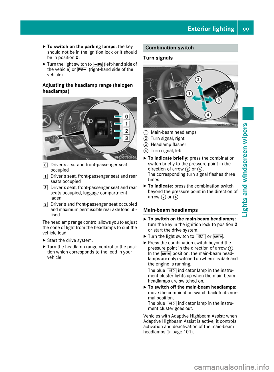
Adjusting the headlamp range (halogen
headlamps) g
Driver's seat and front-passenger seat
occupied
1 Driver's seat, front-passenger seat and rear
seats occupied
2 Driver's seat, front-passenger seat and rear
seats occupied, luggage compartment
laden
3 Driver's and front-passenger seat occupied
and maximum permissible rear axle load uti-
lised
The headlamp range control allows you to adjust
the cone of light from the headlamps to suit the
vehicle load.
X Start the drive system.
X Turn the headlamp range control to the posi-
tion which corresponds to the load in your
vehicle. Combination switch
Turn signals :
Main-beam headlamps
; Turn signal, right
= Headlamp flasher
? Turn signal, left
X To indicate briefly: press the combination
switch briefly to the pressure point in the
direction of arrow ;or?.
The corresponding turn signal flashes three
times.
X To indicate: press the combination switch
beyond the pressure point in the direction of
arrow ;or?.
Main-beam headlamps X
To switch on the main-beam headlamps:
turn the key in the ignition lock to position 2
or start the drive system.
X Turn the light switch to LorÃ.
X Press the combination switch beyond the
pressure point in the direction of arrow :.
In the Ãposition, the main-beam head-
lamps are only switched on when it is dark and the engine is running.
The blue Kindicator lamp in the instru-
ment cluster lights up when the main-beam
headlamps are switched on.
X To switch off the main-beam headlamps:
move the combination switch back to its nor-
mal position.
The blue Kindicator lamp in the instru-
ment cluster goes out.
Vehicles with Adaptive Highbeam Assist: when
Adaptive Highbeam Assist is active, it controls
activation and deactivation of the main-beam
headlamps (Y page 101). Exterior lighting
99Lights andwindscreen wipers Z
Page 113 of 293
Never fold a windscreen wiper arm without a
wiper blade back onto the windscreen/rear
window.
Hold the windscreen wiper arm firmly when
you change the wiper blade. If you release the
wiper arm without a wiper blade and it falls
onto the windscreen/rear window, the wind-
screen/rear window may be damaged by the
force of the impact.
Mercedes-Benz recommends that you have
the wiper blades changed at a qualified spe-
cialist workshop.
Replacing the windscreen wiper blades (variant 1) Removing the wiper blades
X Vehicles without KEYLESS-GO: remove the
key from the ignition lock.
X Vehicles with KEYLESS-GO: switch off the
engine.
X Fold the wiper arm away from the windscreen. X
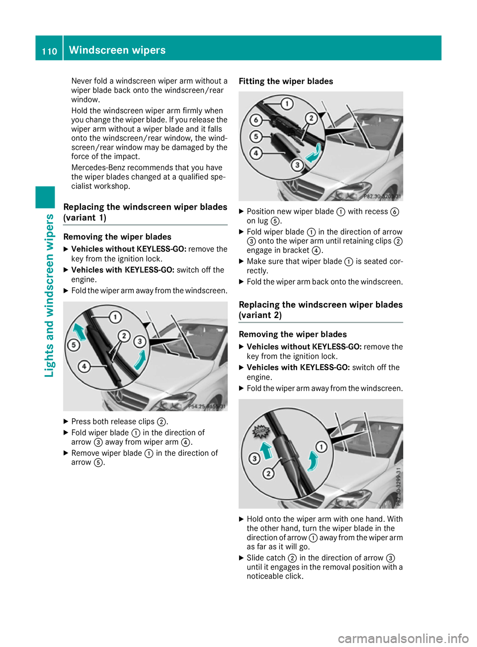
Press both release clips ;.
X Fold wiper blade :in the direction of
arrow =away from wiper arm ?.
X Remove wiper blade :in the direction of
arrow A. Fitting the wiper blades X
Position new wiper blade :with recess B
on lug A.
X Fold wiper blade :in the direction of arrow
= onto the wiper arm until retaining clips ;
engage in bracket ?.
X Make sure that wiper blade :is seated cor-
rectly.
X Fold the wiper arm back onto the windscreen.
Replacing the windscreen wiper blades (variant 2) Removing the wiper blades
X Vehicles without KEYLESS-GO: remove the
key from the ignition lock.
X Vehicles with KEYLESS-GO: switch off the
engine.
X Fold the wiper arm away from the windscreen. X
Hold onto the wiper arm with one hand. With
the other hand, turn the wiper blade in the
direction of arrow :away from the wiper arm
as far as it will go.
X Slide catch ;in the direction of arrow =
until it engages in the removal position with a noticeable click. 110
Windscreen wipersLights and windscreen wipers
Page 125 of 293
With active "Pre-entry climate control at depar-
ture time" the charge status of the high-voltage
battery can be reduced, even if the charge cable connector is connected.
In certain situations, the desired interior tem-
perature cannot be reached.
When the vehicle is cooled, the following func-
tions are activated as necessary:
R Automatic climate control
R cooling with air dehumidification
R blower
When the vehicle is heated, the following func-
tions are activated as necessary:
R Automatic climate control
R Blower
R Seat heating
R Windscreen heating
R Rear window heating
"Immediate pre-entry climate control" is auto-
matically switched off when operational readi-
ness mode is requested.
Setting the departure time You can set a departure time for the "Pre-entry
climate control at departure time". Your vehicle
will then be cooled or heated until the desired
temperature is reached in time for the set depar-
ture time. "Pre-entry climate control at depar-
ture time" will be activated a maximum of
35 minutes before departure. If the departure is delayed, the vehicle will be heated or cooled fora further five minutes.
You can set the desired departure time in the E-
E-
CELL
CELL submenu on the on-board computer
(Y page 184).
Activating immediate pre-entry climate
control You can activate "Immediate pre-entry climate
control" even if the vehicle interior is already at
the desired temperature. This means, for exam- ple, that the vehicle interior continues to be
cooled or heated if the journey is interrupted for up to 50 minutes and the interior temperature iskept constant. You can only set the desired tem-
perature using the climate control unit. If you do not pre-select a temperature, the last tempera-
ture set will be automatically adopted. To activate/deactivate "Immediate pre-
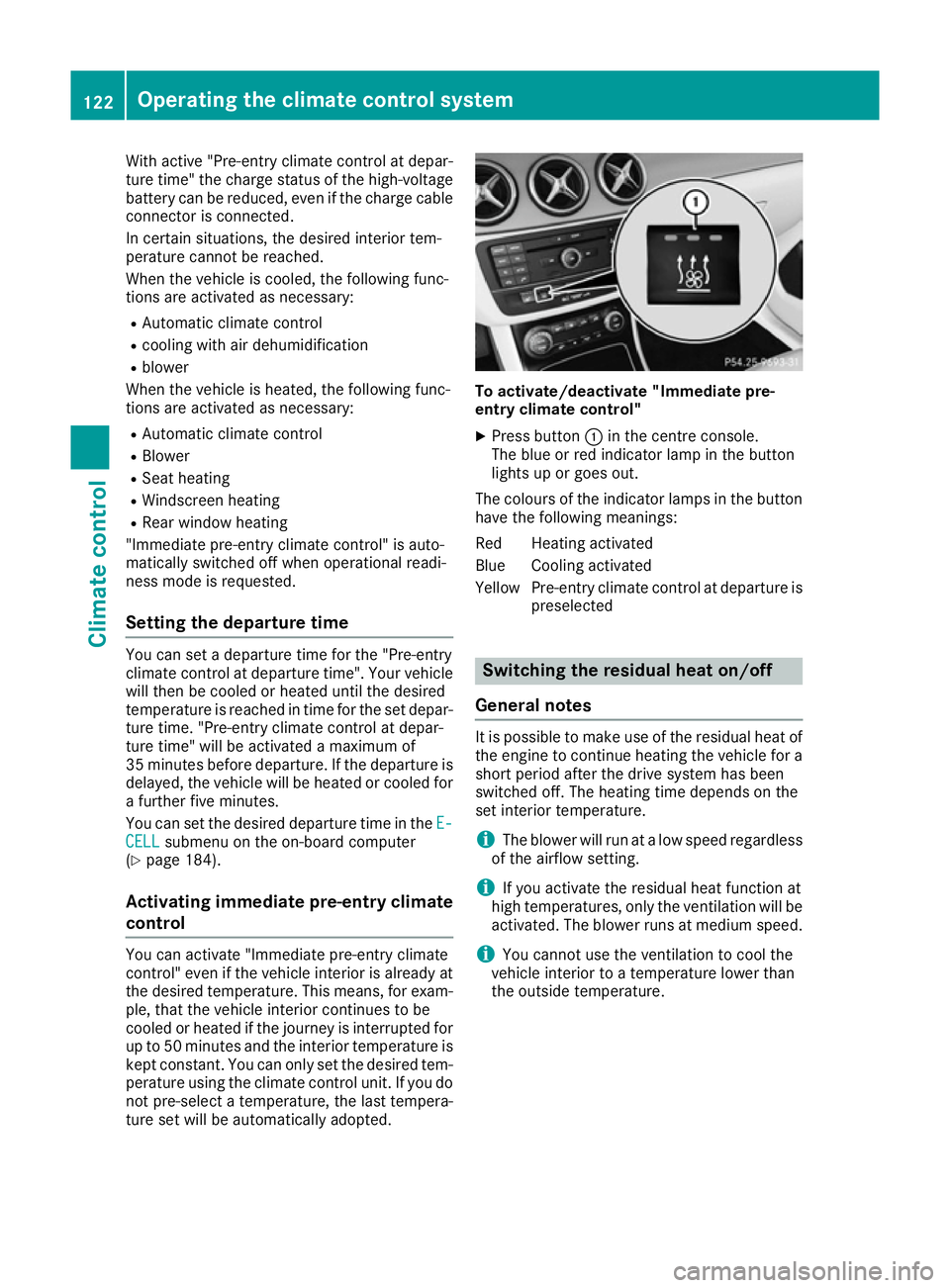
entry climate control"
X Press button :in the centre console.
The blue or red indicator lamp in the button
lights up or goes out.
The colours of the indicator lamps in the button have the following meanings:
Red Heating activated
Blue Cooling activated
Yellow Pre-entry climate control at departure is preselected Switching the residual heat on/off
General notes It is possible to make use of the residual heat of
the engine to continue heating the vehicle for a
short period after the drive system has been
switched off. The heating time depends on the
set interior temperature.
i The blower will run at a low speed regardless
of the airflow setting.
i If you activate the residual heat function at
high temperatures, only the ventilation will be
activated. The blower runs at medium speed.
i You cannot use the ventilation to cool the
vehicle interior to a temperature lower than
the outside temperature. 122
Operating the climate control systemClimate control
Page 130 of 293
Further information on situations where an indi-
cator lamp either fails to go out after starting the drive system or lights up while driving
(Y page 215).
If Start/Stop button :has not yet been
pressed, this corresponds to the key being
removed from the ignition.
X To switch on the power supply: press
Start/Stop button :once.
The power supply is switched on. You can now activate the windscreen wipers, for example.
The power supply is switched off again if:
R the driver's door is opened and
R you press Start/Stop button :twice when in
this position
X To switch on the ignition: press Start/Stop
button :twice.
The ignition is switched on.
If you press Start/Stop button :once when
in this position, the ignition is deactivated
again.
Removing the Start/Stop button
You can remove the Start/Stop button from the
ignition lock and start the vehicle as normal
using the key.
You can only switch between Start/Stop button
mode and key operation when the vehicle is sta- tionary.
You must also engage park position P.
X Remove Start/Stop button :from ignition
lock ;.
You do not have to remove the Start/Stop but-
ton from the ignition lock when you leave the
vehicle. You should, however, always take the
key with you when leaving the vehicle. As long as
the key is in the vehicle:
R the vehicle can be started using the Start/
Stop button
R the electrically powered equipment can be
operated Starting the vehicle
Important safety notes G
WARNING
If children are left unsupervised in the vehicle, they could:
R open doors, thereby endangering other per-
sons or road users
R get out and be struck by oncoming traffic
R operate vehicle equipment and become
trapped, for example
In addition, the children could also set the
vehicle in motion by, for example:
R releasing the parking brake
R shifting the transmission out of park posi-
tion P
R starting the vehicle's drive system
There is a risk of an accident and injury.
When leaving the vehicle, always take the key with you and lock the vehicle. Never leave
children and animals unattended in the vehi-
cle. Keep the keys out of the reach of children.
Vehicles with an electric motor generate signif- icantly less noise than vehicles with internal
combustion engines. As a result, your vehicle
may not be heard by other road users in certain
situations. This can happen, for example, when
you are parking and your vehicle is not seen by
other road users. This requires you to adopt a
particularly anticipatory driving style, as it is
necessary to allow for the possibility that other
road users may behave unpredictably.
The vehicle can be equipped with a sound gen-
erator. The sound generator is activated so that other road users can hear your vehicle better.
The sound generator is activated at speeds
under 30 km/h and switches off automatically
at higher speeds.
Starting procedure using the Start/
Stop button The Start/Stop button can be used to start the
vehicle manually without inserting the key into
the ignition lock. The key must be in the vehicle
and the Start/Stop button must be inserted in
the ignition lock. Driving
127Driving and parking Z
Page 131 of 293
You can start the drive system if a valid key is in
the vehicle. Switch off the drive system and
always take the key with you when leaving the
vehicle, even if you only leave it for a short time. Pay attention to the important safety notes.
X Depress the brake pedal and keep it
depressed.
X Press the Start/Stop button once
(Y page 126).
The drive system is started. Once the vehicle
is ready to be driven, the Ready
Ready display
(Y page 172) appears in the lower part of the
multifunction display.
Starting procedure with the key To start the drive system using the key instead
of the Start/Stop button, pull the Start/Stop
button out of the ignition lock.
X Turn the key to position 3(Y page 126) in the
ignition lock and release it.
The drive system is started. Once the vehicle
is ready to be driven, the Ready Readydisplay
(Y page 172) appears in the lower part of the
multifunction display. Pulling away
The vehicle can be equipped with a sound gen-
erator. At low speeds, an electric vehicle makes
less noise than a vehicle with a combustion
engine. The sound generator is activated so that
other road users can hear your vehicle better.
The sound generator is activated at speeds
under 30 km/h and switches off automatically
at higher speeds.
X Depress the brake pedal and keep it
depressed.
X Move the DIRECT SELECT lever to position D
or R.
X Release the brake pedal.
X Carefully depress the accelerator pedal.
The electric parking brake is automatically
released (Y page 146).
The red !indicator lamp in the instrument
cluster goes out.
The vehicle locks centrally once you have pulled
away. The locking knobs in the doors drop down. You can open the doors from the inside at any
time. It is only possible to move the DIRECT SELECT
selector lever from position
Pto the desired
selector lever position if you depress the brake
pedal. The parking lock is then deactivated and
the electrical parking brake is released auto-
matically. If the brake pedal is not depressed,
the DIRECT SELECT lever can still be moved but
the parking lock remains engaged.
Make sure that no charging cables are connec-
ted. The parking lock cannot be released if a
charging cable is connected. Hill start assist
Hill start assist will aid you when pulling away on
a hill. It holds the vehicle for a short time after
you have removed your foot from the brake
pedal. This gives you enough time to move your foot from the brake pedal to the accelerator
pedal and depress it before the vehicle begins to
roll away. G
WARNING
After a while, hill start assist no longer holds
the vehicle and it may roll away. There is a risk of an accident and injury.
Therefore, quickly move your foot from the
brake pedal to the accelerator pedal. Never
leave the vehicle when it is held by hill start
assist.
Hill start assist is not active if:
R you are pulling away on a level road or a
downhill gradient
R the DIRECT SELECT lever is in position N
R the electric parking brake is applied
R ESP ®
is malfunctioning
Further information on holding the vehicle sta-
tionary on uphill gradients (Y page 131). Transmission
Important safety notes
Shift the DIRECT SELECT lever to position P
when the drive system is switched off and the
vehicle is stationary. Park position Pis engaged
and the electric parking brake is applied auto-
matically. 128
TransmissionDriving and parking
Page 137 of 293
recuperation. Have the radar sensors checked
at a qualified specialist workshop immediately.
Automatic adjustment of recuperation
on downhill gradients The vehicle can detect steep downhill gradients.
To reduce acceleration downhill and to charge
the high-voltage battery, recuperation is
increased steplessly. This is comparable to the
engine brake in a combustion engine when you
downshift a gear on a downhill gradient.
Automatic adjustment of recuperation on down-
hill gradients is available in level DAUTO
or on
vehicles without steering wheel gearshift pad-
dles in level D.
Intelligent recuperation The vehicle uses the map and camera data of
Traffic Sign Assist in addition to the sensors of
COLLISION PREVENTION ASSIST PLUS during
radar-based recuperation ( DAUTO
). The rate of
recuperation is then automatically adjusted to
the current traffic situation, taking the current
and future maximum speed into account. High-voltage battery
Important safety notes
G
DANGER
The vehicle's high voltage electrical system is under high voltage. If you modify components
in the vehicle's high-voltage electrical system or touch damaged components, you may be
electrocuted. The components in the vehi-
cle's high-voltage electrical system may be
damaged in an accident, although the damage
is not visible. There is a risk of fatal injury.
Do not touch any high-voltage components
after an accident and never modify the vehi-
cle's high-voltage electrical system. Have the vehicle towed away after an accident and the vehicle's high-voltage electrical system
checked by a qualified specialist workshop. G
WARNING
In the event of a vehicle fire, the internal pres- sure of the high-voltage battery could exceed a critical value. In this case, flammable gas
escapes through a vent valve in the vehicle's
underbody. The gas can ignite. There is a risk of injury.
Leave the danger area immediately. Secure
the danger area at a suitable distance, whilst
observing legal requirements. G
DANGER
Connecting the charging cable to the mains
supply via incorrectly installed mains sockets or by means of adapters, extension cables or
similar could cause a fire or an electric shock. There is a risk of fatal injury.
To avoid such risks, observe the following:
R Only connect the charging cable to mains
sockets:
- which have been properly installed and
- which have been inspected by a qualified
electrician
R For safety reasons, only use charging
cables which have been supplied with the
vehicle or which have been approved for
this vehicle.
R Never use a damaged charging cable.
R Do not use:
- extension cables
- extension reels
- multi-outlet sockets
R Never use socket adapters to connect the
charging cable to the mains socket. The
only exception is if the adapter has been
tested and approved by the manufacturer
for charging the high-voltage battery of an
electric vehicle.
R Observe the safety notes in the operating
instructions for the socket adapter. G
DANGER
Connecting the charging cable to the wallbox via an incorrectly installed wallbox or adapter,
extension cable or similar could cause a fire or an electric shock. There is a risk of fatal injury. 134
High-voltage batteryDriving and parking
Page 145 of 293
i
Depending on the temperature, the engine
cooling system and battery cooling system
may audibly switch on when the charging
cable is connected or during the charging
process.
Removing the charging cable !
Before driving away, you must ensure that,
for your own safety and to avoid damage, the charging cable has been removed from the
vehicle socket. Otherwise, you cannot shift
the transmission out of position P.
When the charge level display reaches 100%,
the battery is fully charged (Y page 174).
The indicator lamps in the vehicle socket and on the charging cable may stay on for up to
30 seconds after the charging cable has been
disconnected.
When the battery is charged:
X Unlock the vehicle.
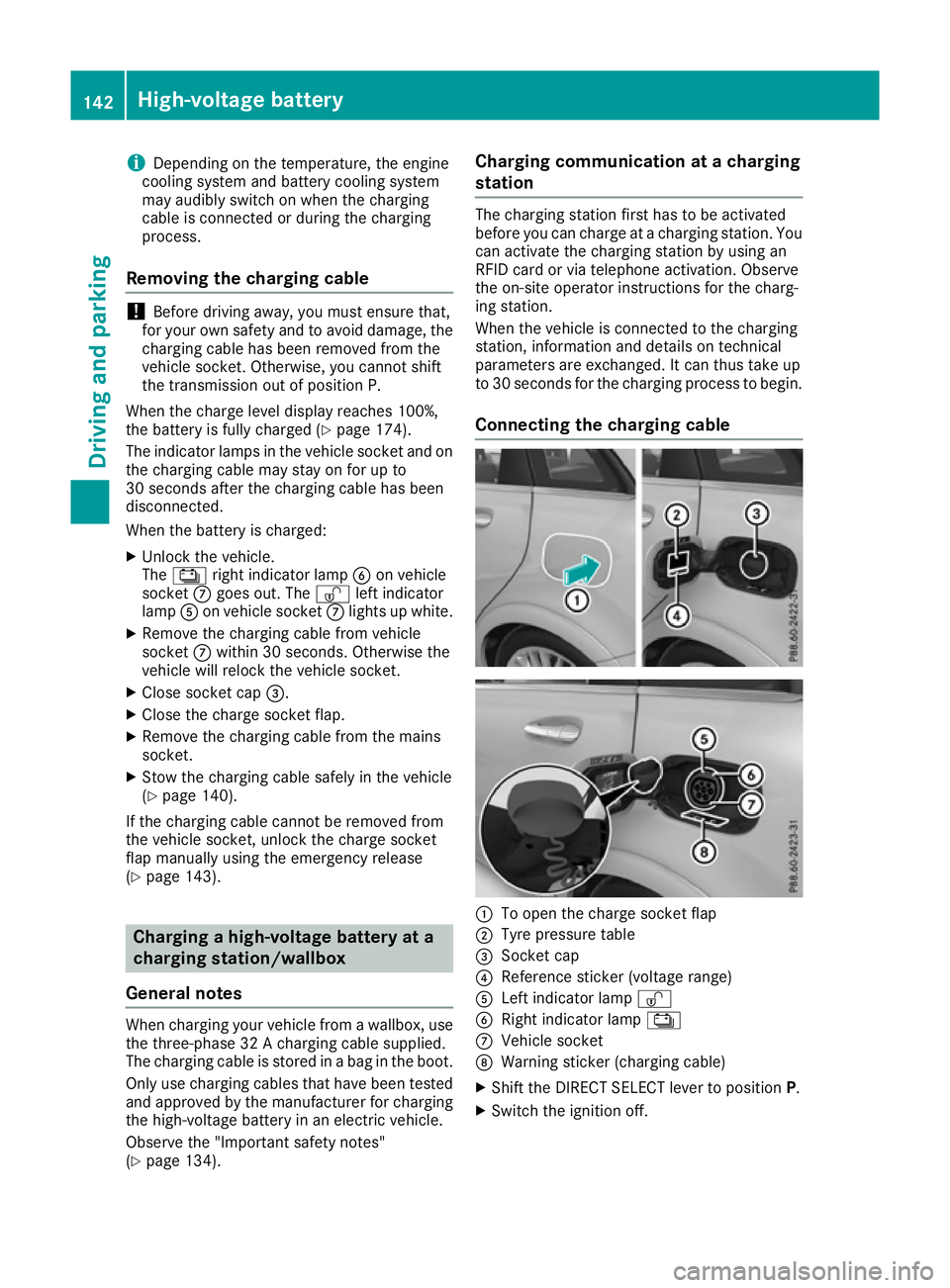
The Ý right indicator lamp Bon vehicle
socket Cgoes out. The Ìleft indicator
lamp Aon vehicle socket Clights up white.
X Remove the charging cable from vehicle
socket Cwithin 30 second s. Otherwise the
vehicle will relock the vehicle socket.
X Close socket cap =.
X Close the charge socket flap.
X Remove the charging cable from the mains
socket.
X Stow the charging cable safely in the vehicle
(Y page 140).
If the charging cable cannot be removed from
the vehicle socket, unlock the charge socket
flap manually using the emergency release
(Y page 143). Charging a high-voltage battery at a
charging station/wallbox
General notes When charging your vehicle from a wallbox, use
the three-phase 32 A charging cable supplied.
The charging cable is stored in a bag in the boot.
Only use charging cables that have been tested
and approved by the manufacturer for charging
the high-voltage battery in an electric vehicle.
Observe the "Important safety notes"
(Y page 134). Charging communication at a charging
station The charging station first has to be activated
before you can charge at a charging station. You
can activate the charging station by using an
RFID card or via telephone activation. Observe
the on-site operator instructions for the charg-
ing station.
When the vehicle is connected to the charging
station, information and details on technical
parameters are exchanged. It can thus take up
to 30 seconds for the charging process to begin.
Connecting the charging cable :
To open the charge socket flap
; Tyre pressure table
= Socket cap
? Reference sticker (voltage range)
A Left indicator lamp Ì
B Right indicator lamp Ý
C Vehicle socket
D Warning sticker (charging cable)
X Shift the DIRECT SELECT lever to position P.
X Switch the ignition off. 142
High-voltage batteryDriving and parking
Page 146 of 293
X
Press the charge socket flap in the direction
of arrow :.
The charge socket flap swings up.
X Remove socket cap =.
X Insert the charging cable connector into vehi-
cle socket Cto the stop.
X Wallbox without a preinstalled cable: insert
the charging cable connector into the power
socket of the wallbox to the stop.
The high-voltage battery is charging.
The Ý right indicator lamp Bon vehicle
socket Cflashes green.
The vehicle must not be moved while the charg-
ing cable is connected or during charging.
i Depending on the temperature, the engine
cooling system and battery cooling system
may audibly switch on when the charging
cable is connected or during the charging
process.
Removing the charging cable !
Before driving away, you must ensure that,
for your own safety and to avoid damage, the
charging cable has been removed from the
vehicle socket. Otherwise, you cannot shift
the transmission out of position P.
When the charge level display reaches 100%,
the battery is fully charged (Y page 174).
i The indicator lamps in the vehicle socket
and on the charging cable may remain on for
up to 30 seconds after the charging cable has
been disconnected.
When the battery is charged: X Unlock the vehicle.
The Ý right indicator lamp Bon vehicle
socket Cgoes out. The Ìleft indicator
lamp Aon vehicle socket Clights up white.
X Remove the charging cable from vehicle
socket Cwithin 30 seconds. Otherwise the
vehicle will relock the vehicle socket.
X Close socket cap =.
X Close the charge socket flap.
X Wallbox without a preinstalled cable: where
necessary, remove the charging cable from
the wallbox and stow it safely in the vehicle.
If the charging cable cannot be removed from
the vehicle socket, unlock the charge socket
flap manually using the emergency release
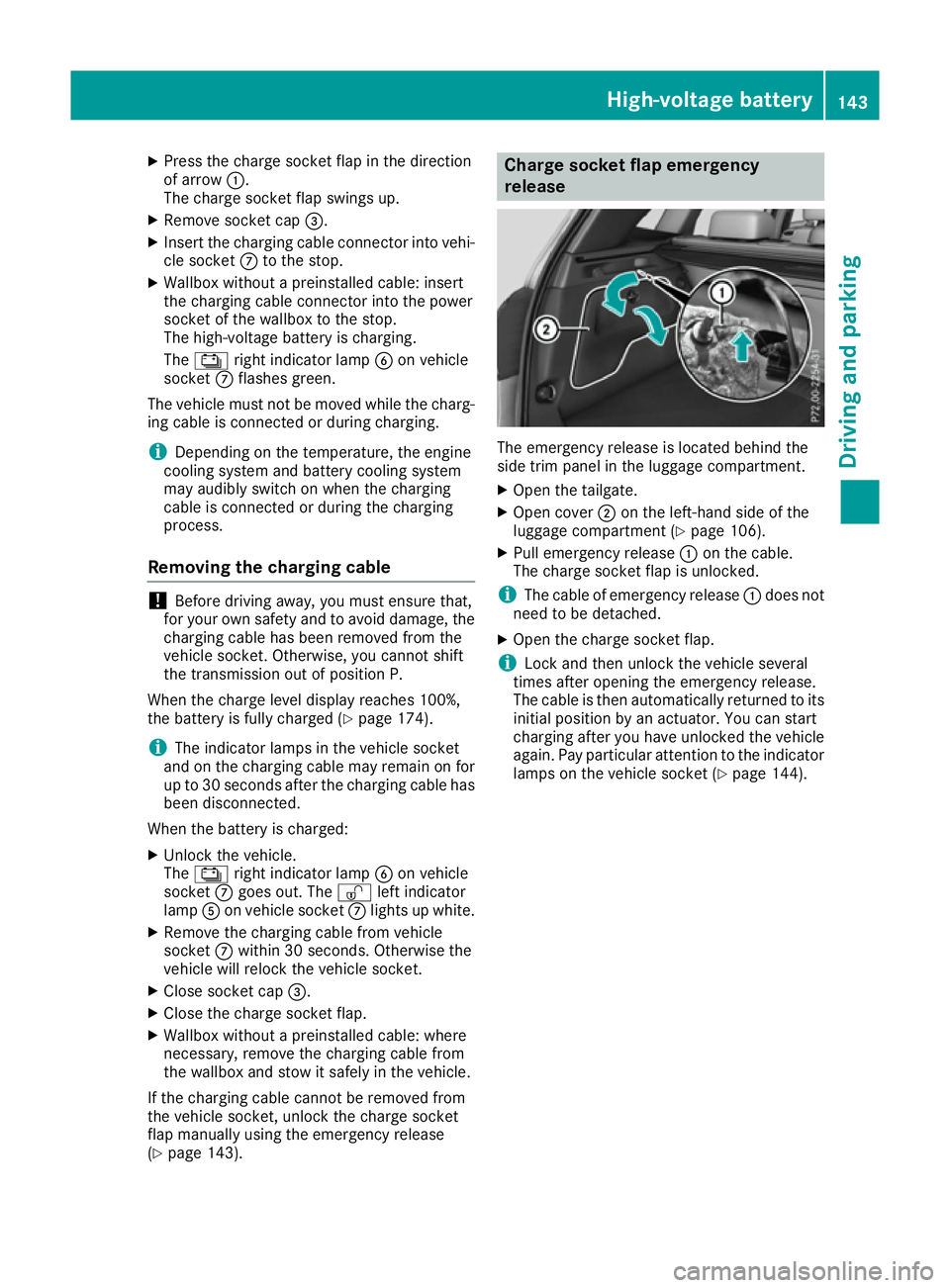
(Y page 143). Charge socket flap emergency
release
The emergency release is located behind the
side trim panel in the luggage compartment.
X
Open the tailgate.
X Open cover ;on the left-hand side of the
luggage compartment (Y page 106).
X Pull emergency release :on the cable.
The charge socket flap is unlocked.
i The cable of emergency release
:does not
need to be detached.
X Open the charge socket flap.
i Lock and then unlock the vehicle several
times after opening the emergency release.
The cable is then automatically returned to its
initial position by an actuator. You can start
charging after you have unlocked the vehicle
again. Pay particular attention to the indicator lamps on the vehicle socket (Y page 144). High-voltage battery
143Driving and parking Z
Page 153 of 293
Driving on wet roads
Aquaplaning If water has accumulated to a certain depth on
the road surface, there is a danger of aquaplan- ing occurring, even if:
R you are driving at low speeds
R the tyres have adequate tread depth
For this reason, drive in the following manner in the event of heavy rain or in conditions in which
aquaplaning can occur:
R lower your speed
R avoid tyre ruts
R avoid sudden steering movements
R brake carefully
Driving on flooded roads !
Bear in mind that vehicles travelling in front
or in the opposite direction create waves. This may cause the maximum permissible water
depth to be exceeded.
These notes must be observed under all cir-
cumstances. You could otherwise damage
the engine, the electronics or the transmis-
sion.
If you must drive on stretches of road on which
water has collected, please bear in mind that:
R in the case of standing water, the water level
must be no higher than the lower edge of the
vehicle body
R you should drive no faster than walking pace Winter driving
G
WARNING
If you increase the recuperation level on slip- pery road surfaces, the drive wheels may lose
their traction. This increases the risk of skid-
ding and having an accident.
Do not increase the recuperation level on slip-
pery road surfaces.
Have your vehicle winterproofed at a qualified
specialist workshop at the onset of winter.
You should drive particularly carefully on slip-
pery road surfaces. Avoid sudden acceleration, steering and braking manoeuvres. Do not use
cruise control.
If the vehicle threatens to skid or cannot be
stopped when moving at low speed:
X Shift the DIRECT SELECT lever to position N.
X Try to bring the vehicle under control by using
corrective steering.
The outside temperature indicator is not
designed to serve as an ice-warning device and
is therefore unsuitable for that purpose.
Changes in the outside temperature are dis-
played after a short delay.
Indicated temperatures just above the freezing
point do not guarantee that the road surface is
free of ice. The road may still be icy, especially in
wooded areas or on bridges.
You should pay special attention to road condi-
tions when temperatures are around freezing
point.
Further information on driving with snow chains (Y page 269).
Further information on driving with summer
tyres (Y page 268).
Observe the notes in the "Winter operation" sec-
tion (Y page 268). Driving systems
Cruise control
General notes Cruise control maintains a constant road speed
for you. It brakes automatically in order to avoid
exceeding the set speed. Change into transmis-
sion position D-
(Y page 132) on long and steep
downhill gradients. This increases recuperation
in overrun mode. This relieves the load on the
brake system and prevents the brakes from
overheating and wearing too quickly.
Use cruise control only if road and traffic con-
ditions are appropriate for maintaining a steady
speed for a prolonged period. You can store any road speed above 30 km/h.
The speed indicated in the speedometer may
differ slightly from the speed stored. 150
Driving syste
msDriving and parking