tailgate MERCEDES-BENZ B-CLASS HATCHBACK 2015 User Guide
[x] Cancel search | Manufacturer: MERCEDES-BENZ, Model Year: 2015, Model line: B-CLASS HATCHBACK, Model: MERCEDES-BENZ B-CLASS HATCHBACK 2015Pages: 293, PDF Size: 10.83 MB
Page 110 of 293
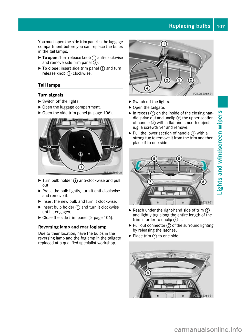
You must open the side trim panel in the luggage
compartment before you can replace the bulbs
in the tail lamps.
X To open: Turn release knob :anti-clockwise
and remove side trim panel ;.
X To close: insert side trim panel ;and turn
release knob :clockwise.
Tail lamps Turn signals
X Switch off the lights.
X Open the luggage compartment.
X Open the side trim panel (Y page 106).X
Turn bulb holder :anti-clockwise and pull
out.
X Press the bulb lightly, turn it anti-clockwise
and remove it.
X Insert the new bulb and turn it clockwise.
X Insert bulb holder :and turn it clockwise
until it engages.
X Close the side trim panel (Y page 106).
Reversing lamp and rear foglamp Due to their location, have the bulbs in the
reversing lamp and the foglamp in the tailgate
replaced at a qualified specialist workshop. X
Switch off the lights.
X Open the tailgate.
X In recess ?on the inside of the closing han-
dle, prise out and unclip ;the upper section
of handle =with a flat and smooth object,
e.g. a screwdriver and remove.
X Pull the lower section of handle :with a
strong tug to remove it from the trim and then place it to one side. X
Reach under the right-hand side of trim B
and lightly tug along the entire length of the
trim in order to unclip Ait.
X Pull out connector Cof the surround lighting
by releasing the latches.
X Place trim Bto one side. Replacing bulbs
107Lights and windscreen wipers Z
Page 111 of 293
X
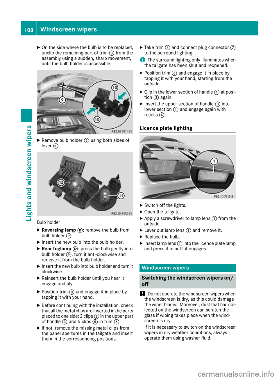
On the side where the bulb is to be replaced,
unclip the remaining part of trim Dfrom the
assembly using a sudden, sharp movement,
until the bulb holder is accessible. X
Remove bulb holder Eusing both sides of
lever F. Bulb holder
X Reversing lamp G: remove the bulb from
bulb holder E.
X Insert the new bulb into the bulb holder.
X Rear foglamp H: press the bulb gently into
bulb holder E, turn it anti-clockwise and
remove it from the bulb holder.
X Insert the new bulb into bulb holder and turn it
clockwise.
X Reinsert the bulb holder until you hear it
engage audibly.
X Position trim Dand engage it in place by
tapping it with your hand.
X Before continuing with the installation, check
that all the metal clips are inserted in the parts placed to one side: 2 clips ;in the upper part
of handle =and 5 clips Ain trim B.
X If not, remove the missing metal clips from
the panel apertures in the tailgate and insert
them in the corresponding positions. X
Take trim Band connect plug connector C
to the surround lighting.
i The surround lighting only illuminates when
the tailgate has been shut and reopened.
X Position trim Band engage it in place by
tapping it with your hand, starting from the
outside.
X Clip in the lower section of handle :at posi-
tion ;again.
X Insert the upper section of handle =into
lower section :and engage again with
recess ?.
Licence plate lighting X
Switch off the lights.
X Open the tailgate.
X Apply a screwdriver to lamp lens :from the
outside.
X Lever out lamp lens :and remove it.
X Replace the bulb.
X Insert lamp lens :into the licence plate lamp
and press it in until it engages. Windscreen wipers
Switching the windscreen wipers on/
off
! Do not operate the windscreen wipers when
the windscreen is dry, as this could damage
the wiper blades. Moreover, dust that has col-
lected on the windscreen can scratch the
glass if wiping takes place when the wind-
screen is dry.
If it is necessary to switch on the windscreen wipers in dry weather conditions, always
operate them using washer fluid. 108
Windscreen wipersLights and windscreen wipers
Page 112 of 293
!
If the windscreen wipers leave smears on
the windscreen after the vehicle has been
washed in an automatic car wash, this may be
due to wax or other residue. Clean the wind-
screen with washer fluid after an automatic
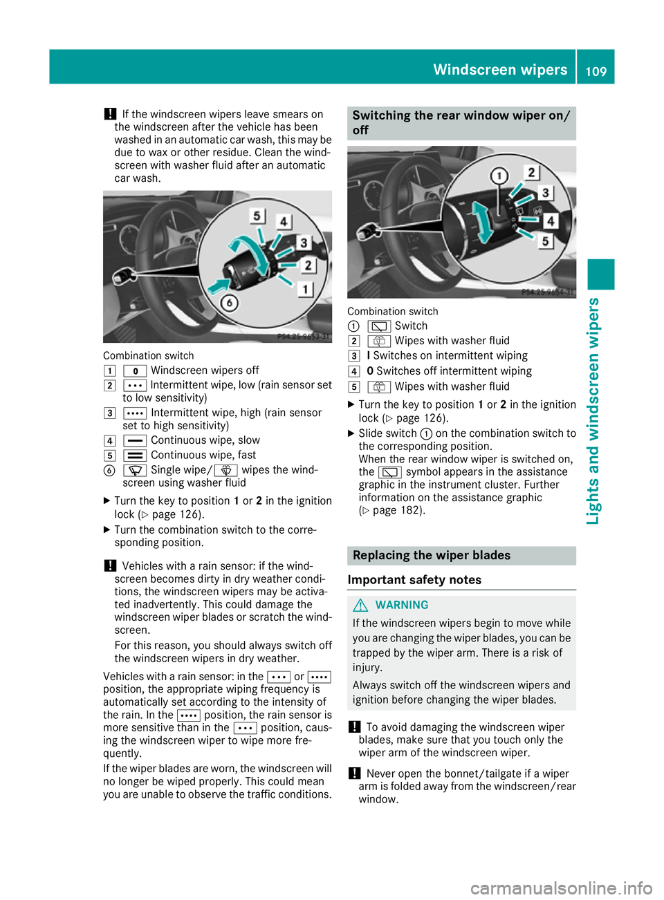
car wash. Combination switch
1
$ Windscreen wipers off
2 Ä Intermittent wipe, low (rain sensor set
to low sensitivity)
3 Å Intermittent wipe, high (rain sensor
set to high sensitivity)
4 ° Continuous wipe, slow
5 ¯ Continuous wipe, fast
B í Single wipe/î wipes the wind-
screen using washer fluid
X Turn the key to position 1or 2in the ignition
lock (Y page 126).
X Turn the combination switch to the corre-
sponding position.
! Vehicles with a rain sensor: if the wind-
screen becomes dirty in dry weather condi-
tions, the windscreen wipers may be activa-
ted inadvertently. This could damage the
windscreen wiper blades or scratch the wind- screen.
For this reason, you should always switch off
the windscreen wipers in dry weather.
Vehicles with a rain sensor: in the ÄorÅ
position, the appropriate wiping frequency is
automatically set according to the intensity of
the rain. In the Åposition, the rain sensor is
more sensitive than in the Äposition, caus-
ing the windscreen wiper to wipe more fre-
quently.
If the wiper blades are worn, the windscreen will
no longer be wiped properly. This could mean
you are unable to observe the traffic conditions. Switching the rear window wiper on/
off Combination switch
:
è Switch
2 ô Wipes with washer fluid
3 ISwitches on intermittent wiping
4 0Switches off intermittent wiping
5 ô Wipes with washer fluid
X Turn the key to position 1or 2in the ignition
lock (Y page 126).
X Slide switch :on the combination switch to
the corresponding position.
When the rear window wiper is switched on,
the è symbol appears in the assistance
graphic in the instrument cluster. Further
information on the assistance graphic
(Y page 182). Replacing the wiper blades
Important safety notes G
WARNING
If the windscreen wipers begin to move while
you are changing the wiper blades, you can be trapped by the wiper arm. There is a risk of
injury.
Always switch off the windscreen wipers and
ignition before changing the wiper blades.
! To avoid damaging the windscreen wiper
blades, make sure that you touch only the
wiper arm of the windscreen wiper.
! Never open the bonnet/tailgate if a wiper
arm is folded away from the windscreen/rear
window. Windscreen wipers
109Lights and windscreen wipers Z
Page 146 of 293
X
Press the charge socket flap in the direction
of arrow :.
The charge socket flap swings up.
X Remove socket cap =.
X Insert the charging cable connector into vehi-
cle socket Cto the stop.
X Wallbox without a preinstalled cable: insert
the charging cable connector into the power
socket of the wallbox to the stop.
The high-voltage battery is charging.
The Ý right indicator lamp Bon vehicle
socket Cflashes green.
The vehicle must not be moved while the charg-
ing cable is connected or during charging.
i Depending on the temperature, the engine
cooling system and battery cooling system
may audibly switch on when the charging
cable is connected or during the charging
process.
Removing the charging cable !
Before driving away, you must ensure that,
for your own safety and to avoid damage, the
charging cable has been removed from the
vehicle socket. Otherwise, you cannot shift
the transmission out of position P.
When the charge level display reaches 100%,
the battery is fully charged (Y page 174).
i The indicator lamps in the vehicle socket
and on the charging cable may remain on for
up to 30 seconds after the charging cable has
been disconnected.
When the battery is charged: X Unlock the vehicle.
The Ý right indicator lamp Bon vehicle
socket Cgoes out. The Ìleft indicator
lamp Aon vehicle socket Clights up white.
X Remove the charging cable from vehicle
socket Cwithin 30 seconds. Otherwise the
vehicle will relock the vehicle socket.
X Close socket cap =.
X Close the charge socket flap.
X Wallbox without a preinstalled cable: where
necessary, remove the charging cable from
the wallbox and stow it safely in the vehicle.
If the charging cable cannot be removed from
the vehicle socket, unlock the charge socket
flap manually using the emergency release
(Y page 143). Charge socket flap emergency
release
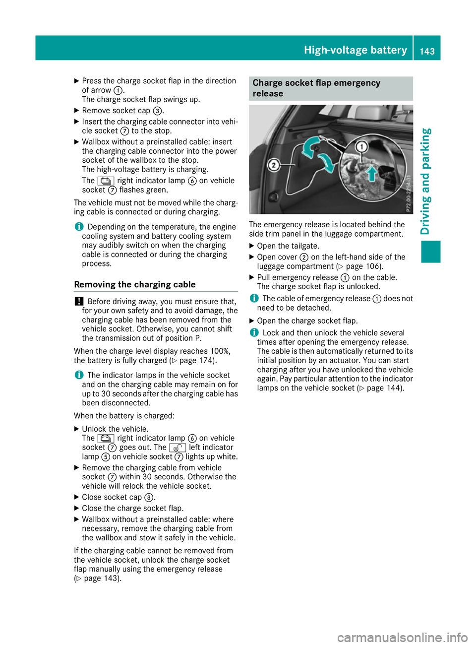
The emergency release is located behind the
side trim panel in the luggage compartment.
X
Open the tailgate.
X Open cover ;on the left-hand side of the
luggage compartment (Y page 106).
X Pull emergency release :on the cable.
The charge socket flap is unlocked.
i The cable of emergency release
:does not
need to be detached.
X Open the charge socket flap.
i Lock and then unlock the vehicle several
times after opening the emergency release.
The cable is then automatically returned to its
initial position by an actuator. You can start
charging after you have unlocked the vehicle
again. Pay particular attention to the indicator lamps on the vehicle socket (Y page 144). High-voltage battery
143Driving and parking Z
Page 150 of 293
Applying automatically
When the vehicle's HOLD function is holding the
vehicle at a standstill, the electric parking brake is engaged automatically.
In addition, at least one of the following condi-
tions must be fulfilled:
R the drive system is switched off
R the driver's door is open and the seat belt is
not fastened
R there is a system malfunction
R the power supply is insufficient
R the vehicle is stationary for a lengthy period
The red !indicator lamp in the instrument
cluster lights up.
Releasing automatically The electric parking brake of your vehicle is
released automatically when all of the following
conditions are fulfilled:
R the vehicle has been started
R the transmission is in position Dor R
R the seat belt is fastened
R you depress the accelerator pedal
If the transmission is in position R, the tailgate
must be closed.
If your seat belt is not fastened, the following
conditions must be fulfilled to automatically
release the electric parking brake:
R the driver's door is closed
R you have shifted out of transmission position
P or you have previously driven faster than
3 km/h
Ensure that you do not depress the accelerator
pedal unintentionally. Otherwise, the parking
brake will be released and the vehicle will start
to move.
Emergency braking The vehicle can also be braked during an emer-
gency by using the electric parking brake.
X While driving, push handle :of the electric
parking brake (Y page 146).
The vehicle is braked as long as you keep
handle :of the electric parking brake
pressed. The longer the electric parking brake
handle :is depressed, the greater the brak-
ing force. During braking:
R a warning tone sounds
R the Release parking brake
Release parking brake message
appears
R the red !indicator lamp in the instrument
cluster flashes
When the vehicle has been braked to a stand-
still, the electric parking brake is applied. Parking up the vehicle
If you leave the vehicle parked up for longer than
four weeks, the battery may be damaged by
exhaustive discharging.
If you leave the vehicle parked up for longer than
six weeks, it may suffer from lack of use.
X Visit a qualified specialist workshop and seek
advice.
i You can obtain information about trickle
chargers from a qualified specialist work-
shop. Driving tips
General notes
Important safety notes G
WARNING
If you switch off the ignition while driving,
safety-relevant functions are only available
with limitations, or not at all. This could affect, for example, the power steering and the brake
boosting effect. You will require considerably
more effort to steer and brake. There is a risk of an accident.
Do not switch off the ignition while driving.
Your vehicle is powered by an electric motor.
The electric motor draws the energy required to
drive the vehicle from the high-voltage battery.
When braking and rolling, kinetic energy is con- verted into electrical energy by energy recovery
and stored in the high-voltage battery.
The range of the vehicle is reduced when con-
sumers are switched on, e.g. THERMOTRONIC. Driving tips
147Driving and pa rking Z
Page 165 of 293
Reversing camera
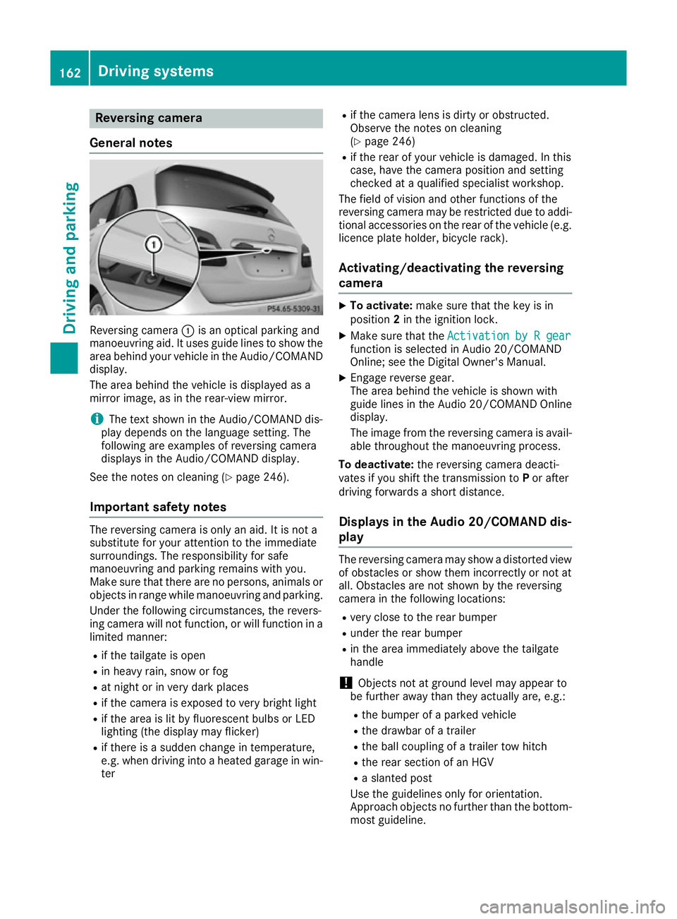
General notes Reversing camera
:is an optical parking and
manoeuvring aid. It uses guide lines to show the
area behind your vehicle in the Audio/COMAND
display.
The area behind the vehicle is displayed as a
mirror image, as in the rear-view mirror.
i The text shown in the Audio/COMAND dis-
play depends on the language setting. The
following are examples of reversing camera
displays in the Audio/COMAND display.
See the notes on cleaning (Y page 246).
Important safety notes The reversing camera is only an aid. It is not a
substitute for your attention to the immediate
surroundings. The responsibility for safe
manoeuvring and parking remains with you.
Make sure that there are no persons, animals or
objects in range while manoeuvring and parking.
Under the following circumstances, the revers-
ing camera will not function, or will function in a limited manner:
R if the tailgate is open
R in heavy rain, snow or fog
R at night or in very dark places
R if the camera is exposed to very bright light
R if the area is lit by fluorescent bulbs or LED
lighting (the display may flicker)
R if there is a sudden change in temperature,
e.g. when driving into a heated garage in win-
ter R
if the camera lens is dirty or obstructed.
Observe the notes on cleaning
(Y page 246)
R if the rear of your vehicle is damaged. In this
case, have the camera position and setting
checked at a qualified specialist workshop.
The field of vision and other functions of the
reversing camera may be restricted due to addi-
tional accessories on the rear of the vehicle (e.g. licence plate holder, bicycle rack).
Activating/deactivating the reversing
camera X
To activate: make sure that the key is in
position 2in the ignition lock.
X Make sure that the Activation by R gear Activation by R gear
function is selected in Audio 20/COMAND
Online; see the Digital Owner's Manual.
X Engage reverse gear.
The area behind the vehicle is shown with
guide lines in the Audio 20/COMAND Online
display.
The image from the reversing camera is avail-
able throughout the manoeuvring process.
To deactivate: the reversing camera deacti-
vates if you shift the transmission to Por after
driving forwards a short distance.
Displays in the Audio 20/COMAND dis-
play The reversing camera may show a distorted view
of obstacles or show them incorrectly or not at
all. Obstacles are not shown by the reversing
camera in the following locations:
R very close to the rear bumper
R under the rear bumper
R in the area immediately above the tailgate
handle
! Objects not at ground level may appear to
be further away than they actually are, e.g.:
R the bumper of a parked vehicle
R the drawbar of a trailer
R the ball coupling of a trailer tow hitch
R the rear section of an HGV
R a slanted post
Use the guidelines only for orientation.
Approach objects no further than the bottom- most guideline. 162
Driving systemsDriving and parking
Page 214 of 293
Display messages
Possible causes/consequences and
M
MSolutions Risk of vehicle
Risk of vehicle
rolling Transmis‐ rolling Transmis‐
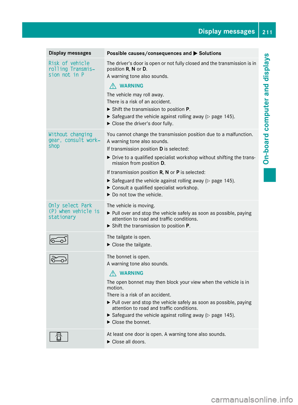
sion not in P sion not in P The driver's door is open or not fully closed and the transmission is in
position R,Nor D.
A warning tone also sounds.
G WARNING
The vehicle may roll away.
There is a risk of an accident.
X Shift the transmission to position P.
X Safeguard the vehicle against rolling away (Y page 145).
X Close the driver's door fully. Without changing
Without changing
gear, consult work‐ gear, consult work‐
shop shop You cannot change the transmission position due to a malfunction.
A warning tone also sounds.
If transmission position
Dis selected:
X Drive to a qualified specialist workshop without shifting the trans-
mission from position D.
If transmission position R,Nor Pis selected:
X Safeguard the vehicle against rolling away (Y page 145).
X Consult a qualified specialist workshop.
X Do not tow the vehicle. Only select Park Only select Park
(P) (P)
when
when vehicle
vehicle is
is
stationary
stationary The vehicle is moving.
X
Pull over and stop the vehicle safely as soon as possible, paying
attention to road and traffic conditions.
X Shift the transmission to position P.A The tailgate is open.
X Close the tailgate. ? The bonnet is open.
A warning tone also sounds.
G WARNING
The open bonnet may then block your view when the vehicle is in
motion.
There is a risk of an accident.
X Pull over and stop the vehicle safely as soon as possible, paying
attention to road and traffic conditions.
X Safeguard the vehicle against rolling away (Y page 145).
X Close the bonnet. C At least one door is open. A warning tone also sounds.
X Close all doors. Display
messages
211On-board computer and displays Z
Page 234 of 293
X
Open both Velcro fasteners and remove the
safety net.
X Unroll and unfold the safety net.
The joints on the upper and lower guide rod
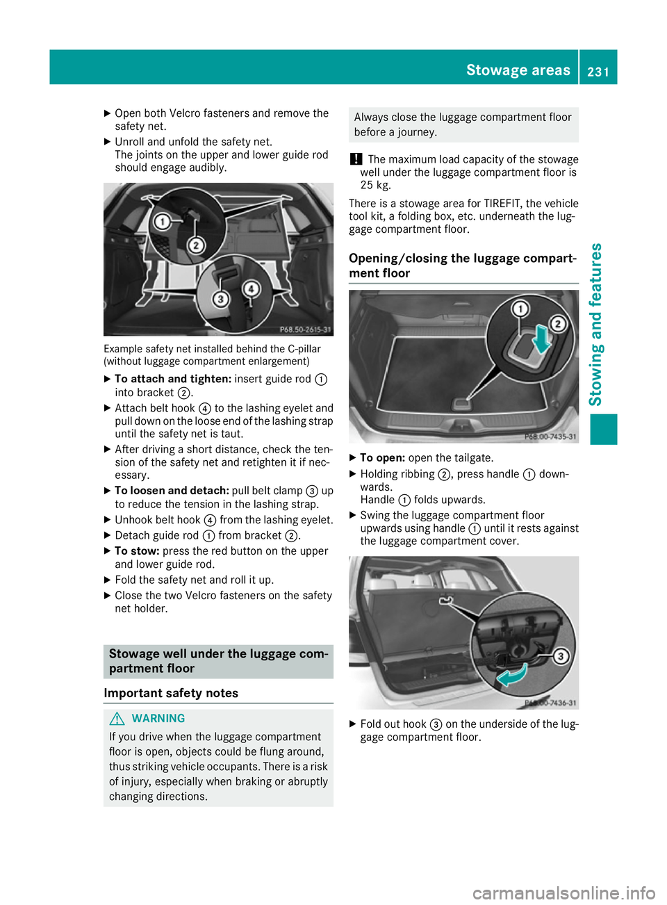
should engage audibly. Example safety net installed behind the C-pillar
(without luggage compartment enlargement)
X To attach and tighten: insert guide rod:
into bracket ;.
X Attach belt hook ?to the lashing eyelet and
pull down on the loose end of the lashing strap until the safety net is taut.
X After driving a short distance, check the ten-
sion of the safety net and retighten it if nec-
essary.
X To loosen and detach: pull belt clamp=up
to reduce the tension in the lashing strap.
X Unhook belt hook ?from the lashing eyelet.
X Detach guide rod :from bracket ;.
X To stow: press the red button on the upper
and lower guide rod.
X Fold the safety net and roll it up.
X Close the two Velcro fasteners on the safety
net holder. Stowage well under the luggage com-
partment floor
Important safety notes G
WARNING
If you drive when the luggage compartment
floor is open, objects could be flung around,
thus striking vehicle occupants. There is a risk of injury, especially when braking or abruptly
changing directions. Always close the luggage compartment floor
before a journey.
! The maximum load capacity of the stowage
well under the luggage compartment floor is
25 kg.
There is a stowage area for TIREFIT, the vehicle tool kit, a folding box, etc. underneath the lug-
gage compartment floor.
Opening/closing the luggage compart-
ment floor X
To open: open the tailgate.
X Holding ribbing ;, press handle :down-
wards.
Handle :folds upwards.
X Swing the luggage compartment floor
upwards using handle :until it rests against
the luggage compartment cover. X
Fold out hook =on the underside of the lug-
gage compartment floor. Stowage areas
231Stowing and features Z
Page 251 of 293
Useful information
i This Owner's Manual describes all models,
series and optional equipment for your vehi-
cle that were available at the time of going to
press. National variations are possible. Note
that your vehicle may not be equipped with all
of the functions described. This is also the
case for systems and functions relevant to
safety.
i Read the information on qualified specialist
workshops: (Y page 23). Where will I find...?
Warning triangle
Removing/replacing the warning trian-
gle X
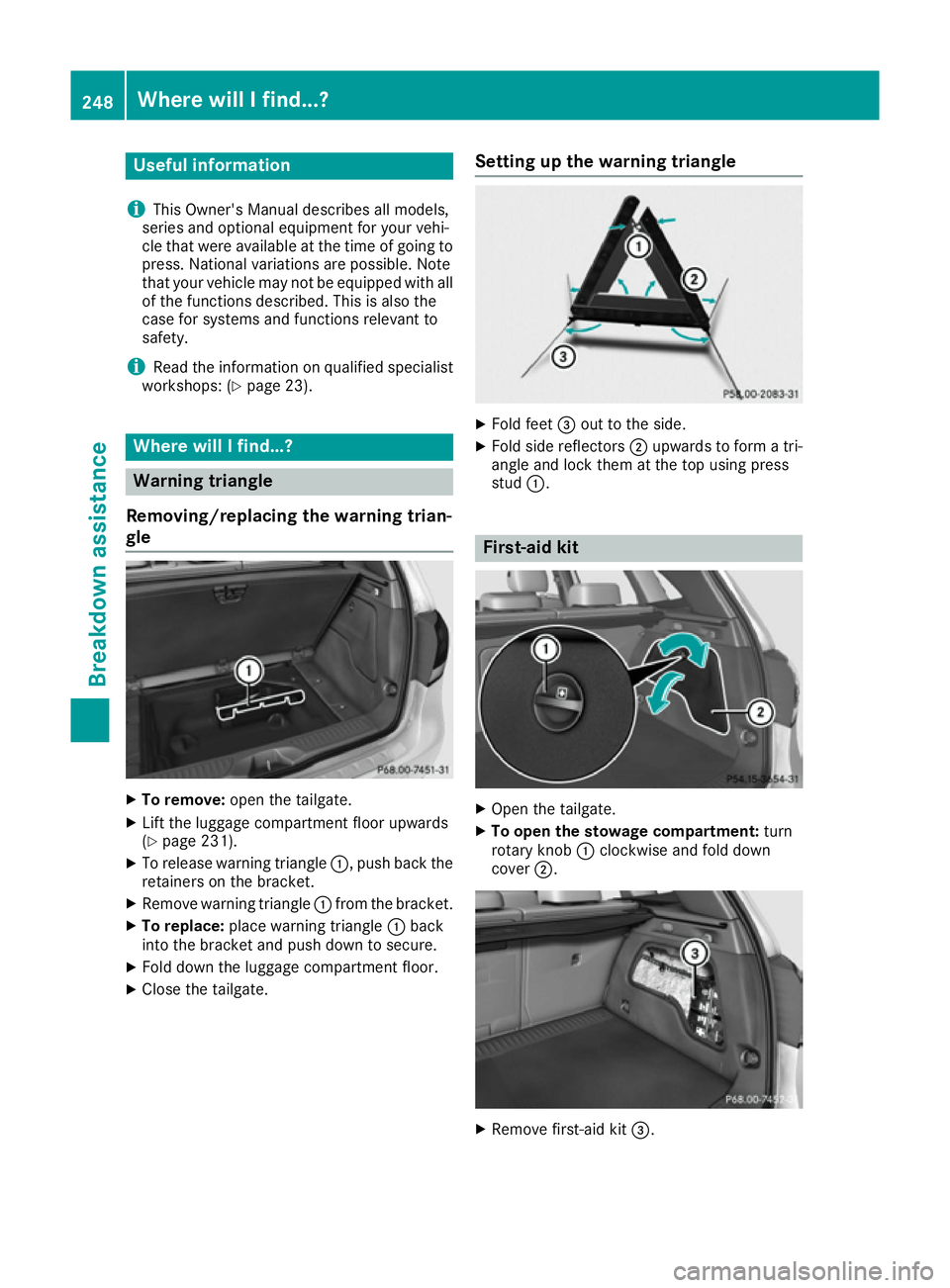
To remove: open the tailgate.
X Lift the luggage compartment floor upwards
(Y page 231).
X To release warning triangle :, push back the
retainers on the bracket.
X Remove warning triangle :from the bracket.
X To replace: place warning triangle :back
into the bracket and push down to secure.
X Fold down the luggage compartment floor.
X Close the tailgate. Setting up the warning triangle X
Fold feet =out to the side.
X Fold side reflectors ;upwards to form a tri-
angle and lock them at the top using press
stud :. First-aid kit
X
Open the tailgate.
X To open the stowage compartment: turn
rotary knob :clockwise and fold down
cover ;. X
Remove first-aid kit =.248
Where will I find...?Breakdown assistance
Page 252 of 293
Check the expiry date on the first-aid kit at least
once a year. Replace the contents if necessary,and replace any missing items. Fire extinguisher
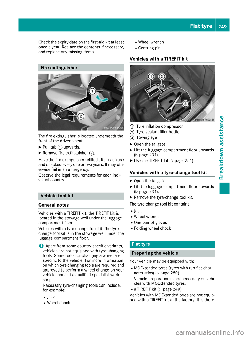
The fire extinguisher is located underneath the
front of the driver's seat.
X Pull tab :upwards.
X Remove fire extinguisher ;.
Have the fire extinguisher refilled after each use and checked every one or two years. It may oth-
erwise fail in an emergency.
Observe the legal requirements for each indi-
vidual country. Vehicle tool kit
General notes Vehicles with a TIREFIT kit: the TIREFIT kit is
located in the stowage well under the luggage
compartment floor.
Vehicles with a tyre-change tool kit: the tyre-
change tool kit is in the stowage well under the
luggage compartment floor.
i Apart from some country-specific variants,
vehicles are not equipped with tyre-changing
tools. Some tools for changing a wheel are
specific to the vehicle. For more information
on which tyre changing tools are required and approved to perform a wheel change on yourvehicle, consult a qualified specialist work-
shop.
Necessary tyre-changing tools can include,
for example:
R Jack
R Wheel chock R
Wheel wrench
R Centring pin
Vehicles with a TIREFIT kit :
Tyre inflation compressor
; Tyre sealant filler bottle
= Towing eye
X Open the tailgate.
X Lift the luggage compartment floor upwards
(Y page 231).
X Use the TIREFIT kit (Y page 251).
Vehicles with a tyre-change tool kit X
Open the tailgate.
X Lift the luggage compartment floor upwards
(Y page 231).
X Remove the tyre-change tool kit.
The tyre-change tool kit contains:
R Jack
R Wheel wrench
R One pair of gloves
R Folding wheel chock Flat tyre
Preparing the vehicle
Your vehicle may be equipped with: R MOExtended tyres (tyres with run-flat char-
acteristics) (Y page 250)
Vehicle preparation is not necessary on vehi- cles with MOExtended tyres.
R a TIREFIT kit (Y page 249)
Vehicles with MOExtended tyres are not equip-
ped with a TIREFIT kit at the factory. It is there- Flat tyre
249Breakdown assistance