warning light MERCEDES-BENZ B-CLASS HATCHBACK 2015 Service Manual
[x] Cancel search | Manufacturer: MERCEDES-BENZ, Model Year: 2015, Model line: B-CLASS HATCHBACK, Model: MERCEDES-BENZ B-CLASS HATCHBACK 2015Pages: 293, PDF Size: 10.83 MB
Page 123 of 293
Problems with the rear window heating
Problem
Possible causes/consequences and
M
MSolutions The rear window heating
has switched off prema-
turely or cannot be acti-
vated. The battery has not been sufficiently charged.
X Switch off any consumers that are not required, e.g. reading lamps,
interior lighting or the seat heating.
When the battery is sufficiently charged, the rear window heating
can be activated again. Switching air-recirculation mode
on/off
General notes You can deactivate the flow of fresh air if
unpleasant odours are entering the vehicle from
outside. The air already inside the vehicle will
then be recirculated.
If you activate air-recirculation mode, the win-
dows can mist up more quickly, in particular at
low temperatures. Only use air-recirculation
mode briefly to prevent the windows misting up.
Switching on/off X
Turn the key to position 2in the ignition lock
(Y page 126).
X To activate: press theebutton.
The indicator lamp in the ebutton lights
up.
Air-recirculation mode is activated automati-
cally:
R at high outside temperatures
R at high levels of pollution
When air-recirculation mode is activated auto-
matically, the indicator lamp in the ebutton
is not lit. Outside air is added after about
30 minutes.
X To deactivate: press theebutton.
The indicator lamp in the ebutton goes
out. i
Air-recirculation mode is deactivated auto-
matically:
R after approximately five minutes at outside
temperatures below approximately 7 †
R after approximately five minutes if the
"Cooling with air dehumidification" func-
tion is deactivated
R after approximately 30 minutes at outside
temperatures above approximately 7 † if
the cooling with air dehumidification func-
tion is activated Convenience opening or closing using
the air-recirculation button G
WARNING
When using convenience closing, you could
become trapped within the sweep of the clos- ing window. There is a risk of injury.
Monitor the entire closing procedure when
using convenience closing. When closing,
make sure that no one has any parts of the
body within the closing area. G
WARNING
During convenience opening parts of the body could be drawn in or become trapped
between the side window and window frame.
There is a risk of injury.
When opening, make sure that nobody is
touching the side window. If someone
becomes trapped, immediately press
the W switch in the door to stop the move-
ment of the side windows. To continue closing
the side window, pull on the Wswitch. 120
Operating the climate control systemClimate control
Page 124 of 293
X
Convenience closing feature: press and
hold the ebutton until the side windows
are closed.
The indicator lamp in the ebutton lights
up. Air-recirculation mode is activated.
If parts of the body are in the closing area during convenience closing, proceed as follows:
X Press the Wbutton for opening/closing
the side windows.
The side windows stop.
X To then open the side windows, press the
W button again.
or
X Press the ebutton for longer than two
seconds.
The side windows move in the opposite direc- tion.
X Convenience opening feature: press and
hold the ebutton until the side windows
are opened. The side windows move back to
their original positions.
The indicator lamp in the ebutton goes
out. Air-recirculation mode is deactivated.
Notes on the reversing feature for the side win-
dows (Y page 82).
If you open the side windows manually after
closing them using the convenience closing fea- ture, they will remain in this position when
opened using the convenience opening feature. Pre-entry climate control via key
Before getting in, the vehicle interior can be
briefly warmed or ventilated in advance. In addi- tion, the air from the air vent can be pre-cooled.
The high-voltage battery must be sufficiently
charged before the "Pre-entry climate control
via key" function can be activated.
Activating/deactivating the pre-entry cli-
mate control (via key)
When the vehicle is unlocked using the key or
KEYLESS-GO, the climate control functions are
activated.
The pre-cooling and pre-heating climate control functions last up to 5 minutes.
When the vehicle is pre-cooled, the following
functions are activated as necessary:
R Automatic climate control
R Cooling with air dehumidification
R Blower When the vehicle is pre-heated, the following
functions are activated as necessary:
R Automatic climate control
R Blower
R Seat heating
R Windscreen heating
R Rear window heating
Pre-entry climate control is automatically
switched off when operational readiness mode
is requested.
Activating/deactivating pre-entry climate
control (via key)
You can activate and deactivate the pre-entry
climate control (via key) function using the on-
board computer in the E-CELL
E-CELL submenu
(Y page 185).
i If the charge status of the high-voltage bat-
tery is below the specified minimum charge
status, pre-entry climate control will not be
activated even if it has been set. Pre-entry climate control at departure
time and immediate pre-entry climate control
Important safety notes G
WARNING
If persons (particularly children) are exposed
to heat or cold for a prolonged period, there is a risk of serious or even fatal injuries. Never
leave persons (particularly children) unatten-
ded in the vehicle.
General notes Using the "Pre-entry climate control at depar-
ture time" function, you can cool or heat the
vehicle interior prior to the desired departure
time.
When using the "Pre-entry climate control at
departure time" function, the charge status of
the high-voltage battery must be higher than the
specified minimum charge status.
The running time of the climate control may be
reduced if:
R the vehicle is not connected to an electric
power supply
R the high-voltage battery is not fully charged Operating the climate control system
121Climate control Z
Page 126 of 293
Switching on/off
X
Turn the key to position 0in the ignition lock
or remove it (Y page 126).
X To activate: press theÌbutton.
The indicator lamp in the Ìbutton lights
up.
X To deactivate: press theÌbutton.
The indicator lamp in the Ìbutton goes
out.
i Residual heat is deactivated automatically:
R after approximately 30 minutes
R when the ignition is switched on
R if the battery voltage drops Air vents
Important safety notes
G
WARNING
Very hot or very cold air can flow from the air vents. This could result in burns or frostbite in the immediate vicinity of the air vents. There
is a risk of injury.
Make sure that all vehicle occupants always
maintain a sufficient distance to the air out-
lets. If necessary, redirect the airflow to
another area of the vehicle interior.
In order to ensure the direct flow of fresh air
through the air vents into the vehicle interior,
please observe the following notes:
R keep the air inlet between the windscreen and
the bonnet free of blockages, such as ice,
snow or leaves
R never cover the vents or ventilation grilles in
the vehicle interior
i Optimal climate control function is achieved
by opening the air vents fully and setting the
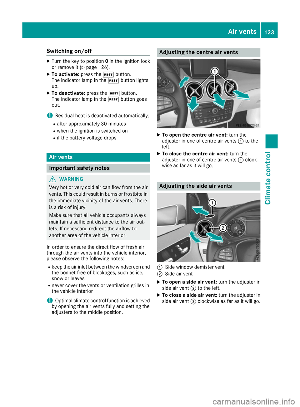
adjusters to the middle position. Adjusting the centre air vents
X
To open the centre air vent: turn the
adjuster in one of centre air vents :to the
left.
X To close the centre air vent: turn the
adjuster in one of centre air vents :clock-
wise as far as it will go. Adjusting the side air vents
:
Side window demister vent
; Side air vent
X To open a side air vent: turn the adjuster in
side air vent ;to the left.
X To close a side air vent: turn the adjuster in
side air vent ;clockwise as far as it will go. Air vents
123Climate control Z
Page 130 of 293
Further information on situations where an indi-
cator lamp either fails to go out after starting the drive system or lights up while driving
(Y page 215).
If Start/Stop button :has not yet been
pressed, this corresponds to the key being
removed from the ignition.
X To switch on the power supply: press
Start/Stop button :once.
The power supply is switched on. You can now activate the windscreen wipers, for example.
The power supply is switched off again if:
R the driver's door is opened and
R you press Start/Stop button :twice when in
this position
X To switch on the ignition: press Start/Stop
button :twice.
The ignition is switched on.
If you press Start/Stop button :once when
in this position, the ignition is deactivated
again.
Removing the Start/Stop button
You can remove the Start/Stop button from the
ignition lock and start the vehicle as normal
using the key.
You can only switch between Start/Stop button
mode and key operation when the vehicle is sta- tionary.
You must also engage park position P.
X Remove Start/Stop button :from ignition
lock ;.
You do not have to remove the Start/Stop but-
ton from the ignition lock when you leave the
vehicle. You should, however, always take the
key with you when leaving the vehicle. As long as
the key is in the vehicle:
R the vehicle can be started using the Start/
Stop button
R the electrically powered equipment can be
operated Starting the vehicle
Important safety notes G
WARNING
If children are left unsupervised in the vehicle, they could:
R open doors, thereby endangering other per-
sons or road users
R get out and be struck by oncoming traffic
R operate vehicle equipment and become
trapped, for example
In addition, the children could also set the
vehicle in motion by, for example:
R releasing the parking brake
R shifting the transmission out of park posi-
tion P
R starting the vehicle's drive system
There is a risk of an accident and injury.
When leaving the vehicle, always take the key with you and lock the vehicle. Never leave
children and animals unattended in the vehi-
cle. Keep the keys out of the reach of children.
Vehicles with an electric motor generate signif- icantly less noise than vehicles with internal
combustion engines. As a result, your vehicle
may not be heard by other road users in certain
situations. This can happen, for example, when
you are parking and your vehicle is not seen by
other road users. This requires you to adopt a
particularly anticipatory driving style, as it is
necessary to allow for the possibility that other
road users may behave unpredictably.
The vehicle can be equipped with a sound gen-
erator. The sound generator is activated so that other road users can hear your vehicle better.
The sound generator is activated at speeds
under 30 km/h and switches off automatically
at higher speeds.
Starting procedure using the Start/
Stop button The Start/Stop button can be used to start the
vehicle manually without inserting the key into
the ignition lock. The key must be in the vehicle
and the Start/Stop button must be inserted in
the ignition lock. Driving
127Driving and parking Z
Page 143 of 293
Stowing the charging cable
The charging cable can be stowed in a bag in the
boot of the vehicle. To do so, the bag must be
secured to the lashing eyelets using the retain-
ing strap provided.
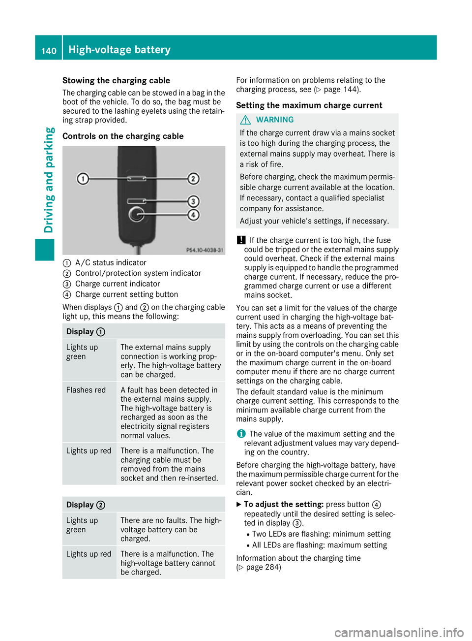
Controls on the charging cable :
A/C status indicator
; Control/protection system indicator
= Charge current indicator
? Charge current setting button
When displays :and ;on the charging cable
light up, this means the following: Display
:
: Lights up
green The external mains supply
connection is working prop-
erly. The high-voltage battery
can be charged.
Flashes red A fault has been detected in
the external mains supply.
The high-voltage battery is
recharged as soon as the
electricity signal registers
normal values.
Lights up red There is a malfunction. The
charging cable must be
removed from the mains
socket and then re-inserted.
Display
; ; Lights up
green There are no faults. The high-
voltage battery can be
charged.
Lights up red There is a malfunction. The
high-voltage battery cannot
be charged. For information on problems relating to the
charging process, see (Y
page 144).
Setting the maximum charge current G
WARNING
If the charge current draw via a mains socket is too high during the charging process, the
external mains supply may overheat. There isa risk of fire.
Before charging, check the maximum permis-
sible charge current available at the location.
If necessary, contact a qualified specialist
company for assistance.
Adjust your vehicle's settings, if necessary.
! If the charge current is too high, the fuse
could be tripped or the external mains supply could overheat. Check if the external mains
supply is equipped to handle the programmed charge current. If necessary, reduce the pro-
grammed charge current or use a different
mains socket.
You can set a limit for the values of the charge
current used in charging the high-voltage bat-
tery. This acts as a means of preventing the
mains supply from overloading. You can set this
limit by using the controls on the charging cable
or in the on-board computer's menu. Only set
the maximum charge current in the on-board
computer menu if there are no charge current
settings on the charging cable.
The default standard value is the minimum
charge current setting. This corresponds to the
minimum available charge current from the
mains supply.
i The value of the maximum setting and the
relevant adjustment values may vary depend-
ing on the country.
Before charging the high-voltage battery, have
the maximum permissible charge current for the relevant power socket checked by an electri-
cian.
X To adjust the setting: press button?
repeatedly until the desired setting is selec-
ted in display =.
R Two LEDs are flashing: minimum setting
R All LEDs are flashing: maximum setting
Information about the charging time
(Y page 284) 140
High-voltage batteryDriving and parking
Page 144 of 293
If, after the charging process, the charging cable
is:
R left connected to the power socket, the cur-
rently selected values will be used for the next
charging process.
R removed from the power socket, the values
will be reset to the minimum setting for the
next charging process. You may then need to reset the values of the maximum charge cur-
rent.
If the charge current values that have been set
on the charging cable and the on-board com-
puter are different, the high-voltage battery is
charged using the lower value.
If the vehicle requires more time than usual to
charge the high-voltage battery, check:
R the settings of the maximum charge current
on the controls of the charging cable
R the settings of the maximum charge current in
the menu of the on-board computer
Indicator lamps on the vehicle socket When the indicator lamps on the vehicle socket
light up, this means the following: Left indicator lamp
Ì Ì Lights up The charging cable can be
connected or removed.
Flashes The charging cable connector
has been connected incor-
rectly. Right indicator lamp
Ý ÝFlashes
slowly in
orange The connection between the
vehicle and the current
source is being established
before charging begins.
Flashes
slowly in
green The high-voltage battery is
charging.
Lights up
green The high-voltage battery is
fully charged.
Flashes rap-
idly in red A malfunction has occurred
while charging. Connecting the charging cable
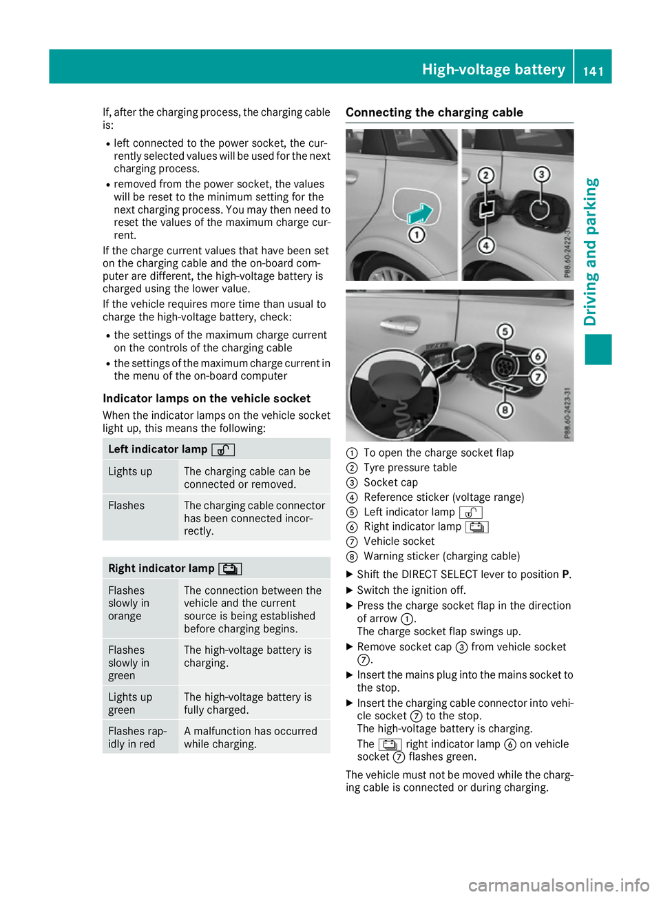
:
To open the charge socket flap
; Tyre pressure table
= Socket cap
? Reference sticker (voltage range)
A Left indicator lamp Ì
B Right indicator lamp Ý
C Vehicle socket
D Warning sticker (charging cable)
X Shift the DIRECT SELECT lever to position P.
X Switch the ignition off.
X Press the charge socket flap in the direction
of arrow :.
The charge socket flap swings up.
X Remove socket cap =from vehicle socket
C.
X Insert the mains plug into the mains socket to
the stop.
X Insert the charging cable connector into vehi-
cle socket Cto the stop.
The high-voltage battery is charging.
The Ý right indicator lamp Bon vehicle
socket Cflashes green.
The vehicle must not be moved while the charg- ing cable is connected or during charging. High-voltage battery
141Driving and parking Z
Page 145 of 293
i
Depending on the temperature, the engine
cooling system and battery cooling system
may audibly switch on when the charging
cable is connected or during the charging
process.
Removing the charging cable !
Before driving away, you must ensure that,
for your own safety and to avoid damage, the charging cable has been removed from the
vehicle socket. Otherwise, you cannot shift
the transmission out of position P.
When the charge level display reaches 100%,
the battery is fully charged (Y page 174).
The indicator lamps in the vehicle socket and on the charging cable may stay on for up to
30 seconds after the charging cable has been
disconnected.
When the battery is charged:
X Unlock the vehicle.
The Ý right indicator lamp Bon vehicle
socket Cgoes out. The Ìleft indicator
lamp Aon vehicle socket Clights up white.
X Remove the charging cable from vehicle
socket Cwithin 30 second s. Otherwise the
vehicle will relock the vehicle socket.
X Close socket cap =.
X Close the charge socket flap.
X Remove the charging cable from the mains
socket.
X Stow the charging cable safely in the vehicle
(Y page 140).
If the charging cable cannot be removed from
the vehicle socket, unlock the charge socket
flap manually using the emergency release
(Y page 143). Charging a high-voltage battery at a
charging station/wallbox
General notes When charging your vehicle from a wallbox, use
the three-phase 32 A charging cable supplied.
The charging cable is stored in a bag in the boot.
Only use charging cables that have been tested
and approved by the manufacturer for charging
the high-voltage battery in an electric vehicle.
Observe the "Important safety notes"
(Y page 134). Charging communication at a charging
station The charging station first has to be activated
before you can charge at a charging station. You
can activate the charging station by using an
RFID card or via telephone activation. Observe
the on-site operator instructions for the charg-
ing station.
When the vehicle is connected to the charging
station, information and details on technical
parameters are exchanged. It can thus take up
to 30 seconds for the charging process to begin.
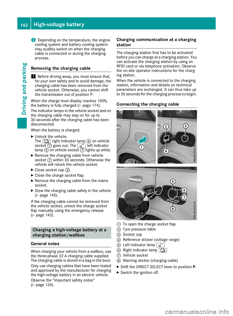
Connecting the charging cable :
To open the charge socket flap
; Tyre pressure table
= Socket cap
? Reference sticker (voltage range)
A Left indicator lamp Ì
B Right indicator lamp Ý
C Vehicle socket
D Warning sticker (charging cable)
X Shift the DIRECT SELECT lever to position P.
X Switch the ignition off. 142
High-voltage batteryDriving and parking
Page 149 of 293
With the key:
X Switch the ignition on.
X Depress the brake pedal and keep it
depressed.
X Shift to neutral N.
X Release the brake pedal.
X Release the electric parking brake.
X Switch off the ignition and leave the key in the
ignition lock.
With the Start/Stop button:
X Remove the Start/Stop button from the igni-
tion lock.
X Insert the key into the ignition lock.
X Switch the ignition on.
X Depress the brake pedal and keep it
depressed.
X Shift to neutral N.
X Release the brake pedal.
X Release the electric parking brake.
X Switch off the ignition and leave the key in the
ignition lock. Electric parking brake
General notes G
WARNING
If you leave children unattended in the vehi-
cle, they may be able to set the vehicle in
motion, for example, if they:
R release the parking brake
R shift the transmission out of park position P
R start the vehicle's drive system
In addition, they may operate vehicle equip-
ment. There is a risk of an accident and injury.
When leaving the vehicle, always take the key
with you and lock the vehicle. Never leave
children unattended in the vehicle. The function of the electric parking brake and
the parking lock is dependent on the on-board
voltage. If the on-board voltage is low or if there
is a malfunction in the system, it may not be
possible to apply the released parking brake or
to shift the transmission to the Pposition.
X If this is the case, only park the vehicle on
level ground and secure it to prevent it from
rolling away.
X Shift the transmission to position P.
It may not be possible to release an applied
parking brake if the on-board voltage is low or if
there is a malfunction in the system. Contact a
qualified specialist workshop.
The electric parking brake carries out a function check at regular intervals when the drive system
is switched off. Noises that occur are normal.
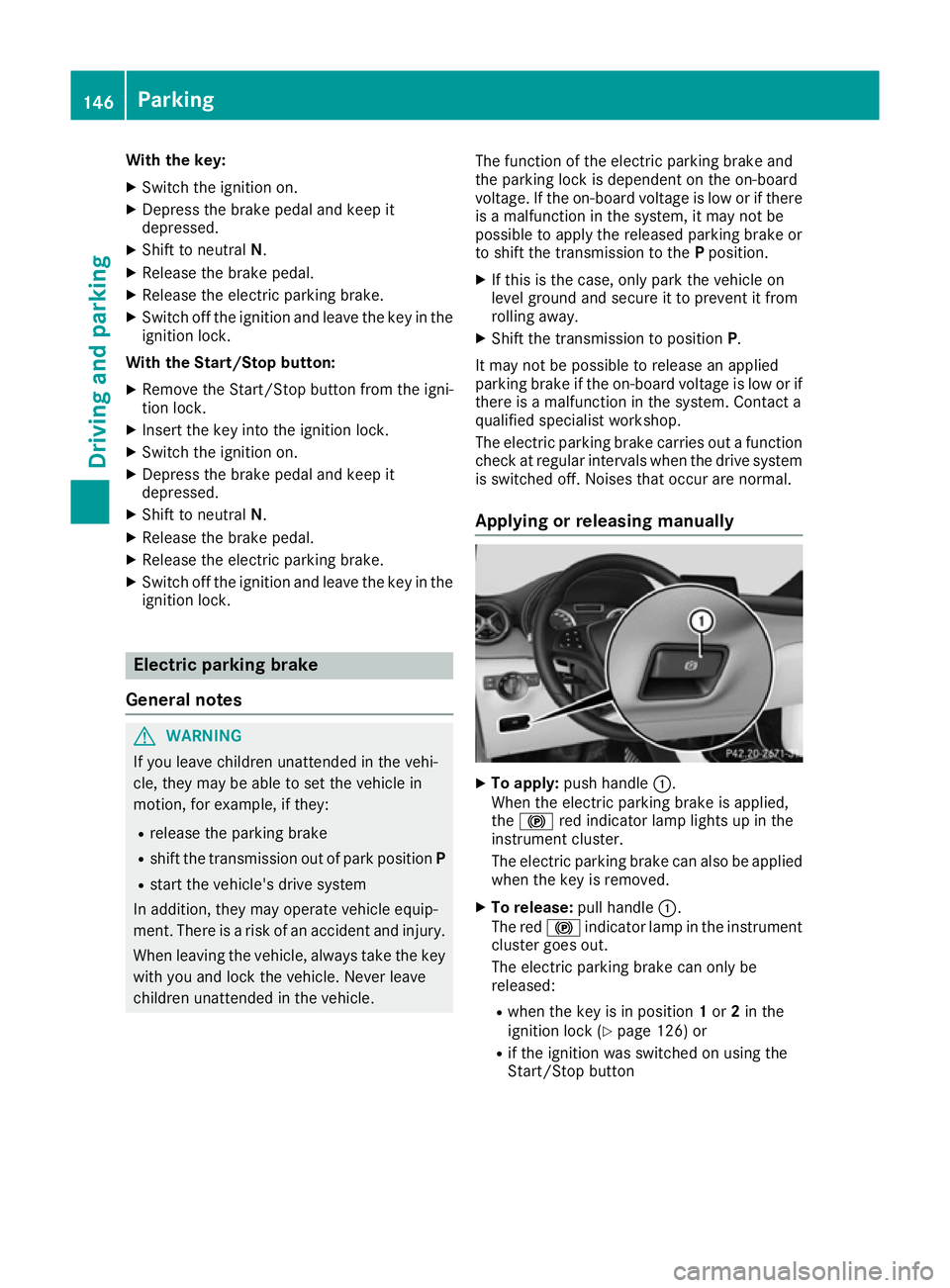
Applying or releasing manually X
To apply: push handle :.
When the electric parking brake is applied,
the ! red indicator lamp lights up in the
instrument cluster.
The electric parking brake can also be applied
when the key is removed.
X To release: pull handle:.
The red !indicator lamp in the instrument
cluster goes out.
The electric parking brake can only be
released:
R when the key is in position 1or 2in the
ignition lock (Y page 126) or
R if the ignition was switched on using the
Start/Stop button 146
ParkingDriving and parking
Page 150 of 293
Applying automatically
When the vehicle's HOLD function is holding the
vehicle at a standstill, the electric parking brake is engaged automatically.
In addition, at least one of the following condi-
tions must be fulfilled:
R the drive system is switched off
R the driver's door is open and the seat belt is
not fastened
R there is a system malfunction
R the power supply is insufficient
R the vehicle is stationary for a lengthy period
The red !indicator lamp in the instrument
cluster lights up.
Releasing automatically The electric parking brake of your vehicle is
released automatically when all of the following
conditions are fulfilled:
R the vehicle has been started
R the transmission is in position Dor R
R the seat belt is fastened
R you depress the accelerator pedal
If the transmission is in position R, the tailgate
must be closed.
If your seat belt is not fastened, the following
conditions must be fulfilled to automatically
release the electric parking brake:
R the driver's door is closed
R you have shifted out of transmission position
P or you have previously driven faster than
3 km/h
Ensure that you do not depress the accelerator
pedal unintentionally. Otherwise, the parking
brake will be released and the vehicle will start
to move.
Emergency braking The vehicle can also be braked during an emer-
gency by using the electric parking brake.
X While driving, push handle :of the electric
parking brake (Y page 146).
The vehicle is braked as long as you keep
handle :of the electric parking brake
pressed. The longer the electric parking brake
handle :is depressed, the greater the brak-
ing force. During braking:
R a warning tone sounds
R the Release parking brake
Release parking brake message
appears
R the red !indicator lamp in the instrument
cluster flashes
When the vehicle has been braked to a stand-
still, the electric parking brake is applied. Parking up the vehicle
If you leave the vehicle parked up for longer than
four weeks, the battery may be damaged by
exhaustive discharging.
If you leave the vehicle parked up for longer than
six weeks, it may suffer from lack of use.
X Visit a qualified specialist workshop and seek
advice.
i You can obtain information about trickle
chargers from a qualified specialist work-
shop. Driving tips
General notes
Important safety notes G
WARNING
If you switch off the ignition while driving,
safety-relevant functions are only available
with limitations, or not at all. This could affect, for example, the power steering and the brake
boosting effect. You will require considerably
more effort to steer and brake. There is a risk of an accident.
Do not switch off the ignition while driving.
Your vehicle is powered by an electric motor.
The electric motor draws the energy required to
drive the vehicle from the high-voltage battery.
When braking and rolling, kinetic energy is con- verted into electrical energy by energy recovery
and stored in the high-voltage battery.
The range of the vehicle is reduced when con-
sumers are switched on, e.g. THERMOTRONIC. Driving tips
147Driving and pa rking Z
Page 152 of 293
The braking performance of the electric motor
using recuperative braking is, in some operating modes, either reduced or not effective:
R when the charge status of the high-voltage
battery increases
R if the high-voltage battery is not yet at a nor-
mal operating temperature
R when driving close to the maximum speed
R when the vehicle is almost stationary
R in transmission position N
R during and after ESP stability control
If you do not make an additional effort to apply
the brake yourself, the braking effect may not be sufficient. If necessary, counteract the reduced regenerative braking effect by applying the
brake yourself.
Downhill gradients On long, steep gradients, you must reduce the
load on the brakes by selecting maximum recu- peration. This prevents the brakes overheating
and causing excessive wear.
Recuperation allows the vehicle to be deceler-
ated without placing a load on the braking sys-
tem.
Do not depress the brake pedal continuously
while the vehicle is in motion, e.g. never cause
the brakes to rub by constantly applying light
pressure to the pedal. This results in excessive
and premature wear to the brake pads.
Heavy and light loads G
WARNING
The braking system can overheat if you leave your foot on the brake pedal while driving.
This increases the braking distance and could
even cause the braking system to fail. There is
a risk of an accident.
Never use the brake pedal as a footrest. Do
not simultaneously depress both the brake
pedal and the accelerator pedal while driving.
! Depressing the brake pedal constantly
results in excessive and premature wear to
the brake pads.
If heavy demands are made on the brakes, do
not park the vehicle immediately. Drive on for a
short while. This allows the airflow to cool the
brakes more quickly. If the brakes have been used only moderately,
you should occasionally test their effectiveness.
To do this, brake more firmly from a higher
speed, paying attention to traffic conditions.
This improves the grip of the brakes.
Wet road surfaces If you have driven for a long time in heavy rain
without braking, there may be a delayed reac-
tion from the brakes when braking for the first
time. This may also occur after a car wash or
after driving through deep water.
You will have to depress the brake pedal more
firmly. Maintain a greater distance to the vehicle
in front.
After driving on a wet road or having the vehicle washed, brake firmly while paying attention to
the traffic conditions. This will warm up the
brake discs, thereby drying them more quickly
and protecting them against corrosion.
Limited braking performance on salt-
treated roads If you drive on salt-treated roads, a layer of salt
may form on the brake discs and pads. This can increase the braking distance considerably.
R In order to prevent any salt build-up, apply the
brakes occasionally while paying attention to the traffic conditions.
R Carefully depress the brake pedal at the end
of the journey and when starting the next
journey.
R Maintain a much greater distance to the vehi-
cle in front.
New brake pads/linings Brake pads/linings and discs that are either new
or have been replaced only achieve optimum
braking effect after several hundred kilometres
of driving. Compensate for the reduced braking effect by applying greater force to the brake
pedal.
For safety reasons, Mercedes-Benz recom-
mends that you only have brake pads/linings
fitted to your vehicle which have been approved
for Mercedes-Benz vehicles or which corre-
spond to an equivalent quality standard. Brake
pads/linings which have not been approved for
Mercedes-Benz vehicles or which are not of an
equivalent quality could affect your vehicle's
operating safety. Driving tips
149Driving and parking Z