height MERCEDES-BENZ B-CLASS SPORTS 2015 User Guide
[x] Cancel search | Manufacturer: MERCEDES-BENZ, Model Year: 2015, Model line: B-CLASS SPORTS, Model: MERCEDES-BENZ B-CLASS SPORTS 2015Pages: 346, PDF Size: 45.04 MB
Page 99 of 346
Problems with the seat heating
ProblemPossible causes/consequences andMSolutions
The seat heating has
switched off prema-
turely or cannot be
switched on.The on-board voltage is too low because too many electrical con-
sumers are switched on.
X Switch off electrical consumers that you do not need, such as
the rear window defroster or interior lighting.
Once the battery is sufficiently charged, the seat heating will
switch back on automatically.
Steering wheel
Important safety notes
GWARNING
You could lose control of your vehicle if you do
the following while driving:
R adjust the driver's seat, head restraint,
steering wheel or mirrors
R fasten the seat belt
There is a risk of an accident.
Adjust the driver's seat, head restraint, steer-
ing wheel and mirror and fasten your seat belt before starting the engine.
GWARNING
Children could injure themselves if they
adjust the steering wheel. There is a risk ofinjury.
When leaving the vehicle, always take the
SmartKey with you and lock the vehicle. Neverleave children unsupervised in the vehicle.
Adjusting the steering wheel
GWARNING
If the steering wheel is unlocked while the
vehicle is in motion, it could change position
unexpectedly. This could cause you to lose
control of the vehicle. There is a risk of anaccident.
Before starting off, make sure the steering
wheel is locked. Never unlock the steering
wheel while the vehicle is in motion.
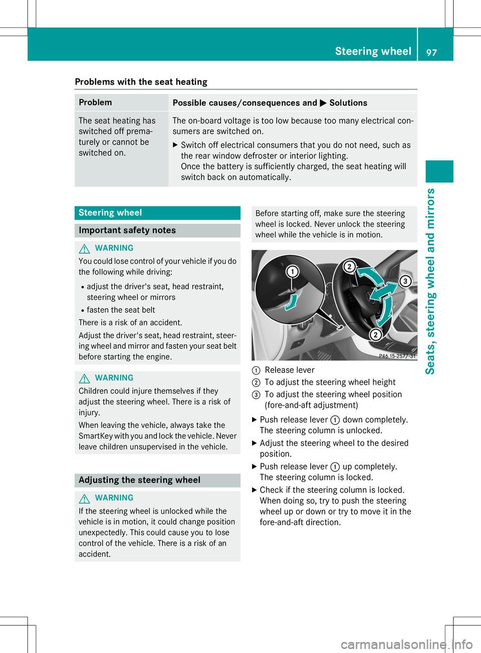
:Release lever
;To adjust the steering wheel height
=To adjust the steering wheel position
(fore-and-aft adjustment)
X Push release lever :down completely.
The steering column is unlocked.
X Adjust the steering wheel to the desiredposition.
X Push release lever :up completely.
The steering column is locked.
X Check if the steering column is locked.
When doing so, try to push the steering
wheel up or down or try to move it in the
fore-and-aft direction.
Steering wheel97
Seats, steering wheel and mirrors
Z
Page 178 of 346
Parking tips:R On narrow roads, drive as close to the park-
ing space as possible.
R Parking spaces that are littered or over-
grown might be identified or measured
incorrectly.
R Parking spaces that are partially occupied
by trailer drawbars might not be identified
as such or be measured incorrectly.
R Snowfall or heavy rain may lead to a parking
space being measured inaccurately.
R Pay attention to the PARKTRONIC(Y page 173) warning messages during the
parking procedure.
R You can intervene in the steering procedure
to correct it at any time. Active Parking
Assist will then be canceled.
R When transporting a load which protrudes
from your vehicle, you should not use
Active Parking Assist.
R Never use Active Parking Assist when snow
chains are installed.
R Make sure that the tire pressures are
always correct. This has a direct influence
on the parking characteristics of the vehi-cle.
Use Active Parking Assist for parking spaces:
R that are parallel or at right-angles to the
direction of travel
R that are on straight roads, not bends
R that are on the same level as the road, e.g.
not on the pavement
Detecting parking spaces
Objects located above the height range of
Active Parking Assist will not be detected
when the parking space is measured. These
are not taken into account when the parking
procedure is calculated, e.g. overhanging
loads, tail sections or loading ramps of goodsvehicles.
GWARNING
If there are objects above the detection range: R Active Park Assist may steer too early
R the vehicle may not stop in front of these
objects.
You may cause a collision as a result. There is
a risk of an accident.
If there are objects above the detection range,
stop and deactivate Active Parking Assist.
For further information on the detection
range ( Ypage 173).
Active Parking Assist does not assist you
parking in spaces at right angles to the direc-
tion of travel if: R two parking spaces are located directly
next to one another
R the parking space is directly next to a low
obstacle such as a low curb
R you park forwards
Active Parking Assist does not assist you
parking in spaces that are parallel or at right
angles to the direction of travel if:
R the parking space is on a curb
R the system reads the parking space as
being blocked, for example by foliage or
grass paving blocks
R the area is too small for the vehicle to
maneuver into
R the parking space is bordered by an obsta-
cle, e.g. a tree, a post or a trailer
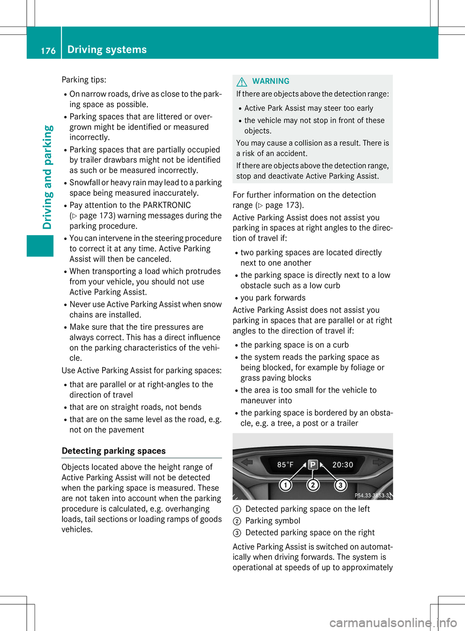
:Detected parking space on the left
;Parking symbol
=Detected parking space on the right
Active Parking Assist is switched on automat-
ically when driving forwards. The system is
operational at speeds of up to approximately
176Driving systems
Driving and parking
Page 256 of 346
XMove the driver's or front-passenger seat
forward if necessary.
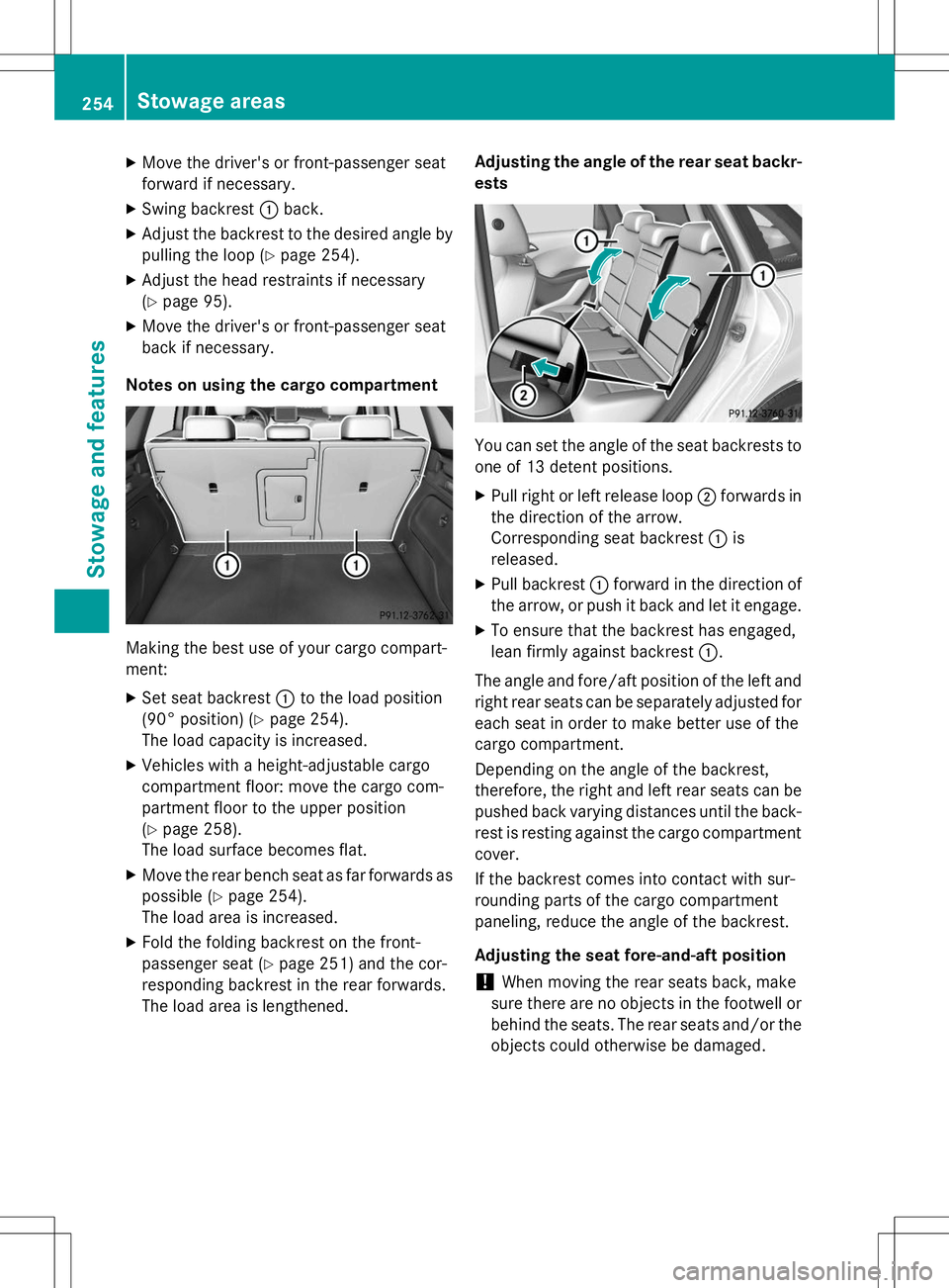
X Swing backrest :back.
X Adjust the backrest to the desired angle by
pulling the loop ( Ypage 254).
X Adjust the head restraints if necessary(Y page 95).
X Move the driver's or front-passenger seat
back if necessary.
Notes on using the cargo compartment
Making the best use of your cargo compart-
ment: X Set seat backrest :to the load position
(90° position) ( Ypage 254).
The load capacity is increased.
X Vehicles with a height-adjustable cargo
compartment floor: move the cargo com-
partment floor to the upper position(Y page 258).
The load surface becomes flat.
X Move the rear bench seat as far forwards as
possible ( Ypage 254).
The load area is increased.
X Fold the folding backrest on the front-
passenger seat ( Ypage 251) and the cor-
responding backrest in the rear forwards.
The load area is lengthened. Adjusting the angle of the rear seat backr-ests
You can set the angle of the seat backrests to
one of 13 detent positions. X Pull right or left release loop ;forwards in
the direction of the arrow.
Corresponding seat backrest :is
released.
X Pull backrest :forward in the direction of
the arrow, or push it back and let it engage.
X To ensure that the backrest has engaged,
lean firmly against backrest :.
The angle and fore/aft position of the left and
right rear seats can be separately adjusted for
each seat in order to make better use of the
cargo compartment.
Depending on the angle of the backrest,
therefore, the right and left rear seats can be pushed back varying distances until the back-
rest is resting against the cargo compartment cover.
If the backrest comes into contact with sur-
rounding parts of the cargo compartment
paneling, reduce the angle of the backrest.
Adjusting the seat fore-and-aft position
!When moving the rear seats back, make
sure there are no objects in the footwell or behind the seats. The rear seats and/or the
objects could otherwise be damaged.
254Stowage areas
Stowage and features
Page 260 of 346
Always close the cargo compartment floor
before a journey.
!The maximum load capacity of the stow-
age well under the cargo compartment
floor is 55 lbs (25 kg).
There is a stowage area for TIREFIT, the vehi-
cle tool kit, a folding box, etc. underneath the
cargo compartment floor.
Opening/closing the cargo compart-
ment floor
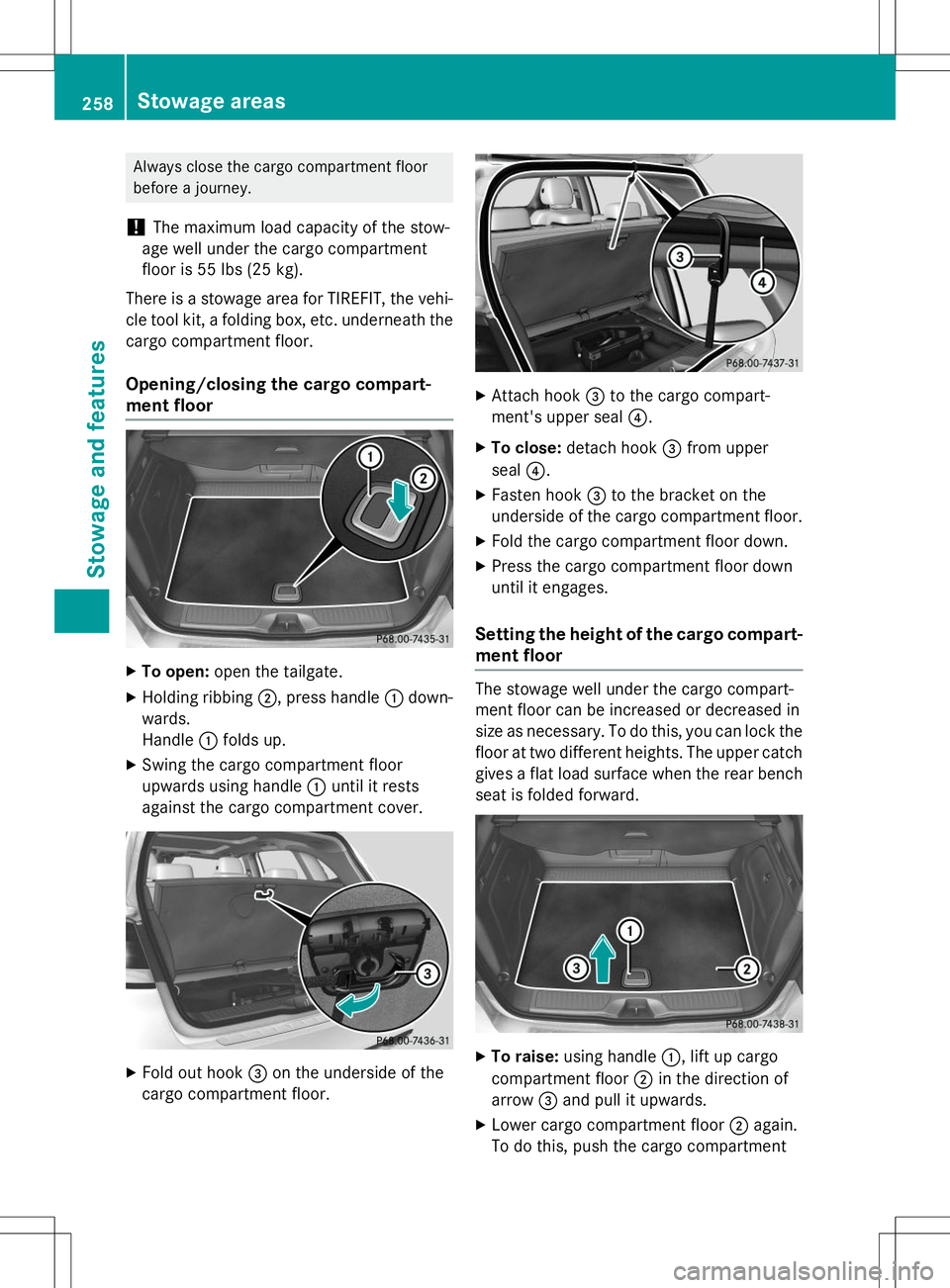
X To open: open the tailgate.
X Holding ribbing ;, press handle :down-
wards.
Handle :folds up.
X Swing the cargo compartment floor
upwards using handle :until it rests
against the cargo compartment cover.
X Fold out hook =on the underside of the
cargo compartment floor.
X Attach hook =to the cargo compart-
ment's upper seal ?.
X To close: detach hook =from upper
seal ?.
X Fasten hook =to the bracket on the
underside of the cargo compartment floor.
X Fold the cargo compartment floor down.
X Press the cargo compartment floor down
until it engages.
Setting the height of the cargo compart-
ment floor
The stowage well under the cargo compart-
ment floor can be increased or decreased in
size as necessary. To do this, you can lock thefloor at two different heights. The upper catch gives a flat load surface when the rear bench
seat is folded forward.
X To raise: using handle :, lift up cargo
compartment floor ;in the direction of
arrow =and pull it upwards.
X Lower cargo compartment floor ;again.
To do this, push the cargo compartment
258Stowage areas
Sto wage an d features
Page 273 of 346
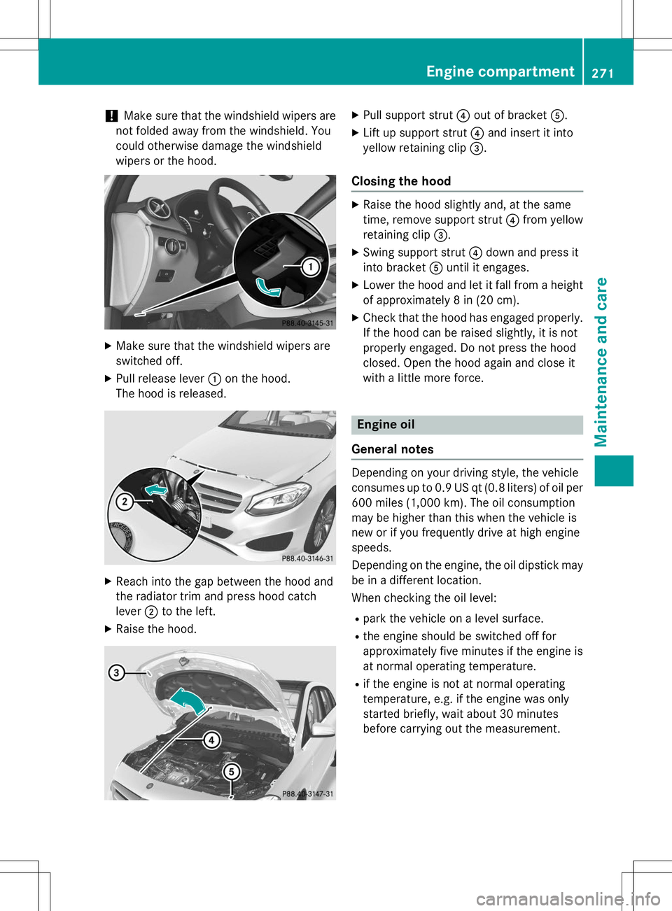
!Make sure that the windshield wipers are
not folded away from the windshield. You
could otherwise damage the windshield
wipers or the hood.
X Make sure that the windshield wipers are
switched off.
X Pull release lever :on the hood.
The hood is released.
X Reach into the gap between the hood and
the radiator trim and press hood catchlever ;to the left.
X Raise the hood.
XPull support strut ?out of bracket A.
X Lift up support strut ?and insert it into
yellow retaining clip =.
Closing the hood
X
Raise the hood slightly and, at the same
time, remove support strut ?from yellow
retaining clip =.
X Swing support strut ?down and press it
into bracket Auntil it engages.
X Lower the hood and let it fall from a height
of approximately 8 in (20 cm).
X Check that the hood has engaged properly.
If the hood can be raised slightly, it is not
properly engaged. Do not press the hood
closed. Open the hood again and close it
with a little more force.
Engine oil
General notes
Depending on your driving style, the vehicle
consumes up to 0.9 US qt (0.8 liters) of oil per 600 miles (1,000 km). The oil consumption
may be higher than this when the vehicle is
new or if you frequently drive at high enginespeeds.
Depending on the engine, the oil dipstick maybe in a different location.
When checking the oil level:
R park the vehicle on a level surface.
R the engine should be switched off for
approximately five minutes if the engine is
at normal operating temperature.
R if the engine is not at normal operating
temperature, e.g. if the engine was only
started briefly, wait about 30 minutes
before carrying out the measurement.
Engine compartment271
Maintenance and care
Z
Page 318 of 346
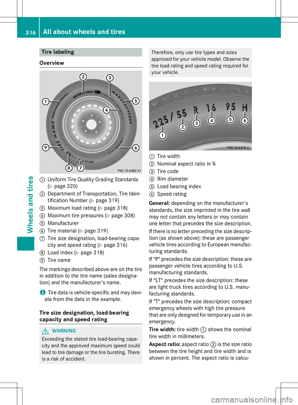
Tire labeling
Overview
:Uniform Tire Quality Grading Standards ( Y page 320)
;Department of Transportation, Tire Iden-
tification Number ( Ypage 319)
=Maximum load rating ( Ypage 318)
?Maximum tire pressures ( Ypage 308)
AManufacturer
BTire material ( Ypage 319)
CTire size designation, load-bearing capa-
city and speed rating ( Ypage 316)
DLoad index ( Ypage 318)
ETire name
The markings described above are on the tire
in addition to the tire name (sales designa-
tion) and the manufacturer's name.
iTire data is vehicle-specific and may devi-
ate from the data in the example.
Tire size designation, load-bearing
capacity and speed rating
GWARNING
Exceeding the stated tire load-bearing capa-
city and the approved maximum speed could
lead to tire damage or the tire bursting. There is a risk of accident.
Therefore, only use tire types and sizes
approved for your vehicle model. Observe the
tire load rating and speed rating required for
your vehicle.
:Tire width
;Nominal aspect ratio in %
=Tire code
?Rim diameter
ALoad bearing index
BSpeed rating
General: depending on the manufacturer's
standards, the size imprinted in the tire wall
may not contain any letters or may contain
one letter that precedes the size description.
If there is no letter preceding the size descrip-
tion (as shown above): these are passenger
vehicle tires according to European manufac-
turing standards.
If "P" precedes the size description: these are
passenger vehicle tires according to U.S.
manufacturing standards.
If "LT" precedes the size description: these
are light truck tires according to U.S. manu-
facturing standards.
If "T" precedes the size description: compact emergency wheels with high tire pressure
that are only designed for temporary use in an
emergency.
Tire width: tire width:shows the nominal
tire width in millimeters.
Aspect ratio: aspect ratio;is the size ratio
between the tire height and tire width and is
shown in percent. The aspect ratio is calcu-
316All about wheels and tires
Wheels and tires
Page 319 of 346
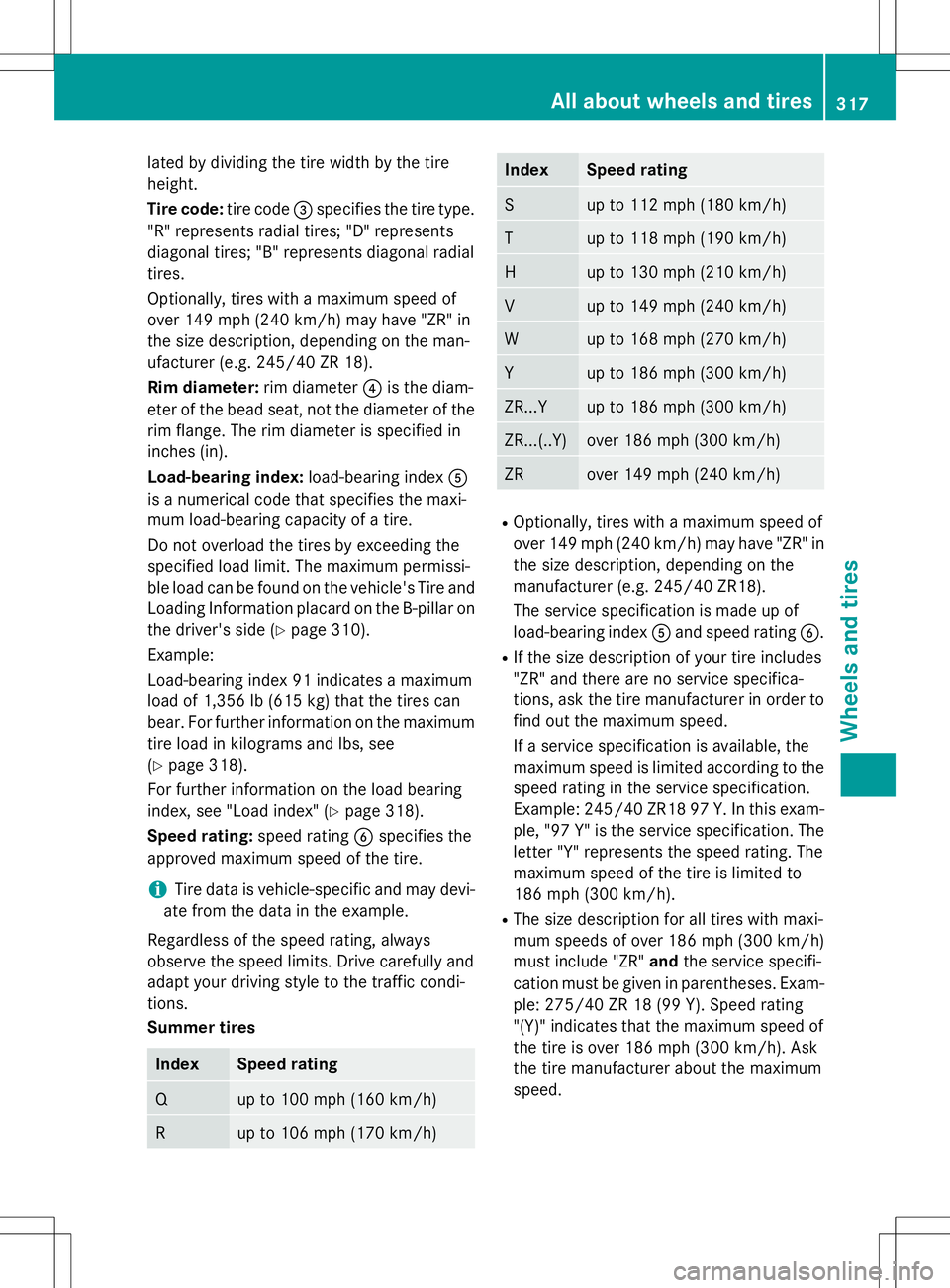
lated by dividing the tire width by the tire
height.
Tire code:tire code=specifies the tire type.
"R" represents radial tires; "D" represents
diagonal tires; "B" represents diagonal radial
tires.
Optionally, tires with a maximum speed of
over 149 mph (240 km/h) may have "ZR" in
the size description, depending on the man-
ufacturer (e.g. 245/40 ZR 18).
Rim diameter: rim diameter?is the diam-
eter of the bead seat, not the diameter of the
rim flange. The rim diameter is specified in
inches (in).
Load-bearing index: load-bearing indexA
is a numerical code that specifies the maxi-
mum load-bearing capacity of a tire.
Do not overload the tires by exceeding the
specified load limit. The maximum permissi-
ble load can be found on the vehicle's Tire and Loading Information placard on the B-pillar on
the driver's side ( Ypage 310).
Example:
Load-bearing index 91 indicates a maximum
load of 1,356 lb (615 kg) that the tires can
bear. For further information on the maximum
tire load in kilograms and lbs, see( Y page 318).
For further information on the load bearing
index, see "Load index" ( Ypage 318).
Speed rating: speed ratingBspecifies the
approved maximum speed of the tire.
iTire data is vehicle-specific and may devi-
ate from the data in the example.
Regardless of the speed rating, always
observe the speed limits. Drive carefully and
adapt your driving style to the traffic condi-
tions.
Summer tires
IndexSpeed rating
Qup to 100 mph (160 km/h)
Rup to 106 mph (170 km/h)
IndexSpeed rating
Sup to 112 mph (180 km/h)
Tup to 118 mph (190 km/h)
Hup to 130 mph (210 km/h)
Vup to 149 mph (240 km/h)
Wup to 168 mph (270 km/h)
Yup to 186 mph (300 km/h)
ZR...Yup to 186 mph (300 km/h)
ZR...(..Y)over 186 mph (300 km/h)
ZRover 149 mph (240 km/h)
R
Optionally, tires with a maximum speed of
over 149 mph (240 km/h) may have "ZR" in
the size description, depending on the
manufacturer (e.g. 245/40 ZR18).
The service specification is made up of
load-bearing index Aand speed rating B.
R If the size description of your tire includes
"ZR" and there are no service specifica-
tions, ask the tire manufacturer in order to
find out the maximum speed.
If a service specification is available, the
maximum speed is limited according to the
speed rating in the service specification.
Example: 245/40 ZR18 97 Y.In this exam-
ple, "97 Y" is the service specification. The letter "Y" represents the speed rating. The
maximum speed of the tire is limited to
186 mph (300 km/h).
R The size description for all tires with maxi-
mum speeds of over 186 mph (300 km/h)
must include "ZR" andthe service specifi-
cation must be given in parentheses. Exam- ple: 275/40 ZR 18 (99 Y). Speed rating
"(Y)" indicates that the maximum speed of
the tire is over 186 mph (300 km/h). Ask
the tire manufacturer about the maximum
speed.
All about wheels and tires317
Wheels and tires
Z
Page 323 of 346
Curb weight
The weight of a vehicle with standard equip-
ment including the maximum capacity of fuel,oil and coolant. It also includes the air-condi-
tioning system and optional equipment if
these are installed in the vehicle, but does not include passengers or luggage.
Maximum load rating
The maximum load rating is the maximum
permissible weight in kilograms or lbs for
which a tire is approved.
Maximum permissible tire pressure
Maximum permissible tire pressure for one
tire.
Maximum load on one tire
Maximum load on one tire. This is calculated
by dividing the maximum axle load of one axleby two.
PSI (pounds per square inch)
A standard unit of measure for tire pressure.
Aspect ratio
Relationship between tire height and tire
width in percent.
Tire pressure
This is pressure inside the tire applying an
outward force to each square inch of the tire's
surface. The tire pressure is specified in
pounds per square inch (psi), in kilopascal
(kPa) or in bar. The tire pressure should only
be corrected when the tires are cold.
Cold tire pressure
The tires are cold:
R if the vehicle has been parked without
direct sunlight on the tires for at least three
hours and
R if the vehicle has not been driven further
than 1 mile (1.6 km) Tread
The part of the tire that comes into contact
with the road.
Bead
The tire bead ensures that the tire sits
securely on the wheel. There are several steel
wires in the bead to prevent the tire from
coming loose from the wheel rim.
Sidewall
The part of the tire between the tread and the bead.
Weight of optional extras
The combined weight of those optional extras
that weigh more than the replaced standard
parts and more than 2.3 kg (5 lbs). These
optional extras, such as high-performance
brakes, level control, a roof rack or a high-
performance battery, are not included in the
curb weight and the weight of the accesso-
ries.
TIN (Tire Identification Number)
This is a unique identifier which can be used
by a tire manufacturer to identify tires, for
example for a product recall, and thus identify the purchasers. The TIN is made up of the
manufacturer's identity code, tire size, tire
type code and the manufacturing date.
Load bearing index
The load bearing index (also load index) is a
code that contains the maximum load bearing
capacity of a tire.
Traction
Traction is the result of friction between the
tires and the road surface.
Treadwear indicators
Narrow bars (tread wear bars) that are dis-
tributed over the tire tread. If the tire tread is level with the bars, the wear limit of áin
(1.6 mm) has been reached.
All about wheels and tires321
Wheels and tires
Z
Page 326 of 346
Observe the following when raising the vehicle:
R To raise the vehicle, only use the vehicle-
specific jack that has been tested and
approved by Mercedes-Benz. If used incor-
rectly, the jack could tip over with the vehi- cle raised.
R The jack is designed only to raise and hold
the vehicle for a short time while a wheel
is being changed. It is not suited for per-
forming maintenance work under the vehi-
cle.
R Avoid changing the wheel on uphill and
downhill slopes.
R Before raising the vehicle, secure it from
rolling away by applying the parking brake
and inserting wheel chocks. Do not disen-
gage the parking brake while the vehicle is
raised.
R The jack must be placed on a firm, flat and
non-slip surface. On a loose surface, a
large, flat, load-bearing underlay must be
used. On a slippery surface, a non-slip
underlay must be used, e.g. rubber mats.
R Do not use wooden blocks or similar
objects as a jack underlay. Otherwise, the
jack will not be able to achieve its load-
bearing capacity due to the restrictedheight.
R Make sure that the distance between the
underside of the tires and the ground does
not exceed 1.2 in (3 cm).
R Never place your hands and feet under the
raised vehicle.
R Do not lie under the vehicle.
R Do not start the engine when the vehicle is
raised.
R Never open or close a door or the tailgate
when the vehicle is raised.
R Make sure that no persons are present in
the vehicle when the vehicle is raised.
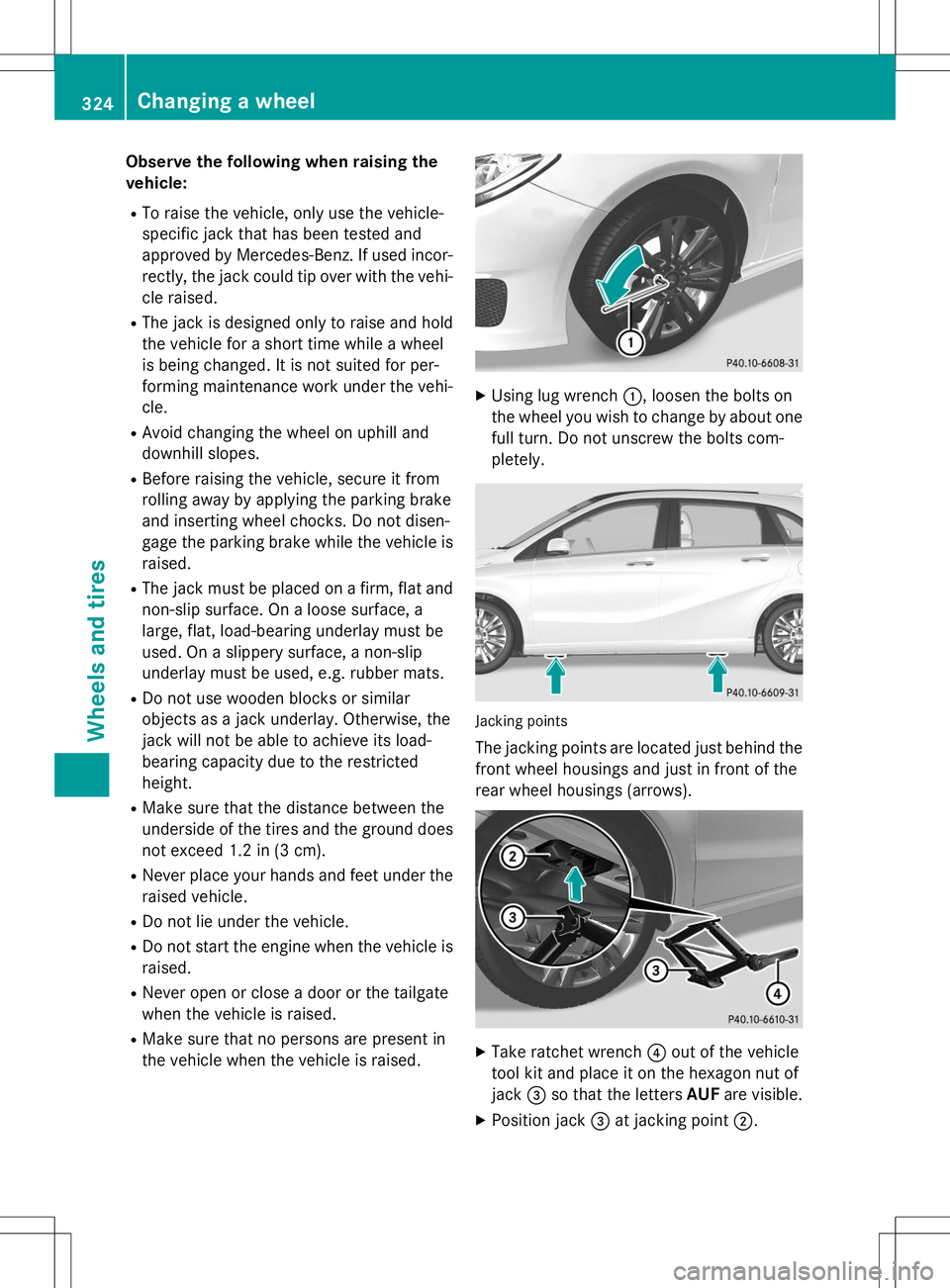
XUsing lug wrench :, loosen the bolts on
the wheel you wish to change by about one full turn. Do not unscrew the bolts com- pletely.
Jacking points
The jacking points are located just behind the front wheel housings and just in front of the
rear wheel housings (arrows).
X Take ratchet wrench ?out of the vehicle
tool kit and place it on the hexagon nut of jack =so that the letters AUFare visible.
X Position jack =at jacking point ;.
324Changing a wheel
Wheels and tires
Page 343 of 346
Vehicle data
General notes
Please note that for the specified vehicle
data:R the heights specified may vary as a resultof:
- tires
- load
- condition of the suspension
- optional equipment
R optional equipment reduces the maximum
payload.
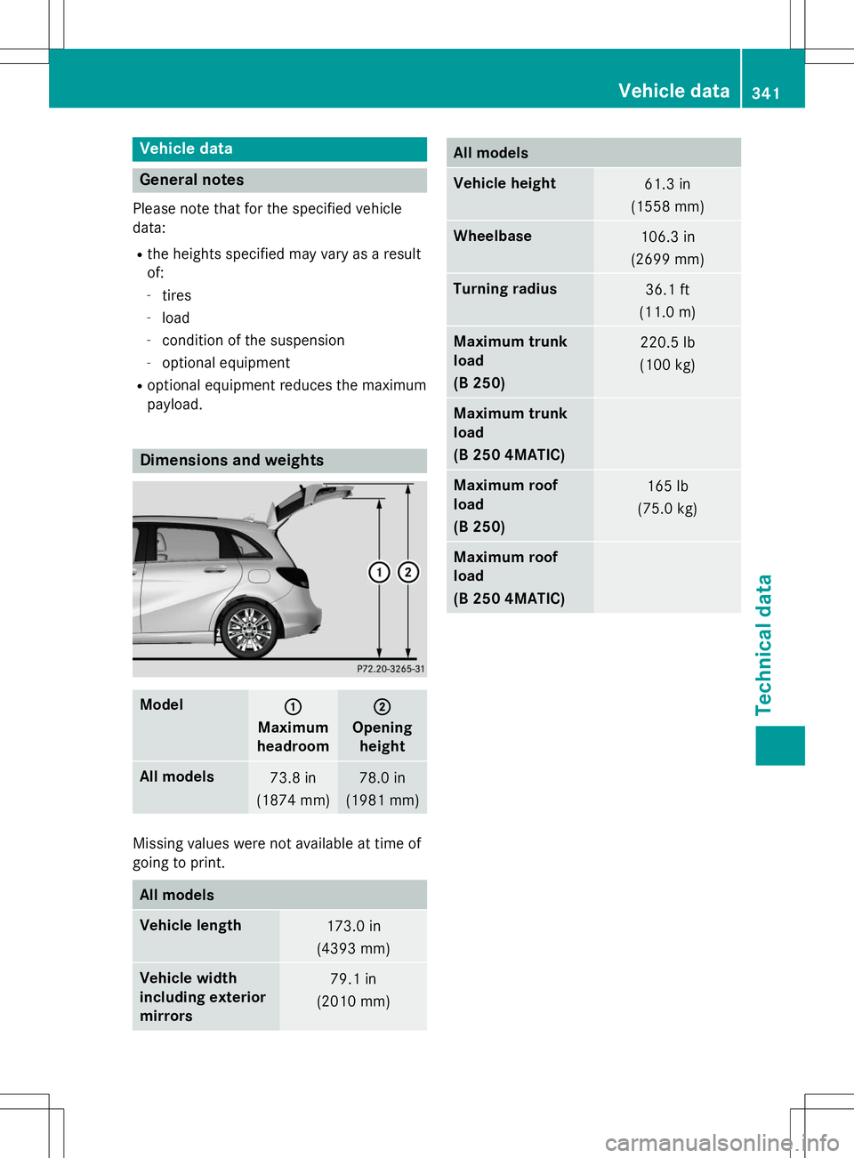
Dimensions and weights
Model:
Maximum
headroom
;
Opening height
All models73.8 in
(1874 mm)78.0 in
(1981 mm)
Missing values were not available at time of
going to print.
All models
Vehicle length173.0 in
(4393 mm)
Vehicle width
including exterior
mirrors79.1 in
(2010 mm)
All models
Vehicle height61.3 in
(1558 mm)
Wheelbase106.3 in
(2699 mm)
Turning radius36.1 ft
(11.0 m)
Maximum trunk
load
(B 250)220.5 lb
(100 kg)
Maximum trunk
load
(B 250 4MATIC)
Maximum roof
load
(B 250)165 lb
(75.0 kg)
Maximum roof
load
(B 250 4MATIC)
Vehicle data341
Technical data
Z