key MERCEDES-BENZ C-CLASS 2002 Owner's Guide
[x] Cancel search | Manufacturer: MERCEDES-BENZ, Model Year: 2002, Model line: C-CLASS, Model: MERCEDES-BENZ C-CLASS 2002Pages: 399, PDF Size: 16.95 MB
Page 76 of 399

73
Restraint systems
Te ch n i c a l
data
Instruments
and controls Operation
DrivingInstrument
cluster display Practical hints Car care Index
The operational readiness of the airbag system is
verified by the indicator lamp “SRS” in the instrument
cluster when turning the electronic key in starter switch
to position 1. When turning the electronic key in starter
switch to position 2 the indicator lamp “SRS” in the
instrument cluster comes on. If no fault is detected, the
lamp will go out when the engine is running. After the
lamp goes out, the system continues to monitor the
components and circuitry of the airbag system and will
indicate a malfunction by coming on again. If the lamp
does not come on at all or if it fails to extinguish or if it
comes on thereafter, a malfunction in the system has
been detected.
The following system components are monitored or
undergo a self-check: crash-sensor(s), airbag ignition
circuits, front seat belt buckles, emergency tensioning
retractors, seat sensor.
Have the system checked at your authorized
Mercedes-Benz Center immediately.
In the operational mode, after the indicator lamp has
gone out following the initial check, interruptions or
short circuits in the airbag ignition circuit and in the
driver and front passenger seat belt buckle harnesses,
and low voltage in the entire
system are detected and
indicated. Note:
See page 285 for information on the supplemental
restraint system (SRS) indicator lamp.
Wa r n i n g !
In the event a malfunction of the “SRS” is indicated
as outlined above, the “SRS” may not be
operational. For your safety, we strongly
recommend that you visit an authorized
Mercedes-Benz Center immediately to have the
system checked; otherwise the “SRS” may not be
activated when needed in an accident, which could
result in serious or fatal injury, or it might deploy
unexpectedly and unnecessarily which could also
result in injury.
ProCarManuals.com
Page 91 of 399
88
Steering wheel adjustment
Te ch n i c a l
data
Instruments
and controls Operation
DrivingInstrument
cluster display Practical hints Car care Index
Steering wheel adjustment (electrical)
(optional)
To adjust the steering wheel position, turn the electronic
key in starter switch to position 1 or 2. With the driver’s
door open, the steering wheel can also be operated with
the electronic key removed or in starter switch
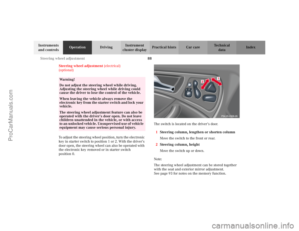
position 0. The switch is located on the driver’s door.
1 Steering column, lengthen or shorten column
Move the switch to the front or rear.
2 Steering column, height
Move the switch up or down.
Note:
The steering wheel adjustment can be stored together
with the seat and exterior mirror adjustment.
See page 93 for notes on the memory function.
Wa r n i n g !
Do not adjust the steering wheel while driving.
Adjusting the steering wheel while driving could
cause the driver to lose the control of the vehicle.When leaving the vehicle always remove the
electronic key from the starter switch and lock your
vehicle.The steering wheel adjustment feature can also be
operated with the driver’s door open. Do not leave
children unattended in the vehicle, or with access
to an unlocked vehicle. Unsupervised use of vehicle
equipment may cause serious personal injury.
ProCarManuals.com
Page 92 of 399
89
Rear view mirrors
Te ch n i c a l
data
Instruments
and controls Operation
DrivingInstrument
cluster display Practical hints Car care Index
Rear view mirrors
Inside rear view mirror
Manually adjust the mirror.
Inside rear view mirror, automatic antiglare
With the electronic key in starter switch position 2, the
mirror reflection brightness responds to changes in
light sensitivity.
With the gear selector lever in position “R”, or with the
interior light switched on, the mirror brightness does
not respond to changes in light sensitivity.
Note:
The automatic antiglare function does not react, if
incoming light is not aimed directly at sensors in the
mirror.
Wa r n i n g !
In the case of an accident liquid electrolyte may
escape the mirror housing when the mirror glass
breaks.Electrolyte has an irritating effect. Do not allow the
liquid come into contact with eyes, skin, clothing,
or respiratory system. In cases it does, immediately
flush affected area with water, and seek medical
help if necessary.
ProCarManuals.com
Page 93 of 399

90
Rear view mirrors
Te ch n i c a l
data
Instruments
and controls Operation
DrivingInstrument
cluster display Practical hints Car care Index
Exterior rear view mirrors
The buttons are located above the exterior lamp switch.
The memory button (4) is located on the driver’s door. Exterior rear view mirror adjustment
Turn the electronic key in starter switch to position 1
or 2.
Push button to select mirror to be adjusted:
Driver’s side – Push button (1).
Passenger side – Push button (2).
Push the adjustment button (3) up, down, left or right
according to the setting desired.
Notes:
The exterior rear view mirrors have electrically heated
glass. The heater switches on automatically, depending
on outside temperature.
If an exterior mirror housing is forcibly pivoted from its
normal position, it must be repositioned by applying
firm pressure until it snaps into place.
Storing rear view mirror positions in memory
(only vehicles with memory function)
The exterior rear view mirror positions are stored in
memory with the seat / steering wheel adjustment and
can be recalled when necessary. See page 93 for notes
on the memory function.
Wa r n i n g !
Exercise care when using the passenger side
exterior mirror. The mirror surface is convex
(outwardly curved surface for a wider field of
view). Objects in mirror are closer than they
appear. Check your inside rear view mirror or
glance over your shoulder before changing lanes.
P88.70-2113-26
ProCarManuals.com
Page 94 of 399
91
Rear view mirrors
Te ch n i c a l
data
Instruments
and controls Operation
DrivingInstrument
cluster display Practical hints Car care Index
Parking position exterior mirror
(only vehicles with memory function)
The passenger side exterior mirror can be adjusted and
programmed to assist the driver during parking
maneuvers (e.g. to observe the curb or other objects
close to the vehicle).
With the electronic key in starter switch position 2, and
the exterior rear view mirror switch in the passenger
side position, the passenger side mirror will be turned
downward when placing the gear selector lever in “R”
reverse.
Note:
For activating the mirror adjustment, see under
individual setting menu “CONVENIENCE” – “MIRROR
SETTING WHEN PARKING”, on page 134.
The passenger side mirror will return to its previous
position:
• immediately at speeds above approx. 6 mph
(10 km / h) – independent of the engaged gear,
• after 10 seconds when shifting gear selector lever
from “R” Reverse,
• by pressing the driver’s side mirror button %. To store passenger mirror parking position:
1. The vehicle must be stationary. Turn the electronic key in starter switch to
position 1 or 2.
2. Select passenger side mirror & and adjust the
mirror to view the curb.
3. Push the memory button “M” (4).
4. Within 3 seconds push bottom of adjustment button (3).
The mirror should not move.
Repeat the memory procedure if the mirror moves.
Note:
One stored parking position is available for each of the
two electronic keys.
This is only possible if you select “ON” in the menu,
“SETTINGS KEY-DEPENDENT”, see under individual
setting menu “CONVENIENCE” – “SETTINGS KEY-
DEPENDENT”, see page 134.
ProCarManuals.com
Page 95 of 399

92
Rear view mirrors
Te ch n i c a l
data
Instruments
and controls Operation
DrivingInstrument
cluster display Practical hints Car care Index
Driver’s side exterior rear view mirror,
antiglare mode
With the electronic key in starter switch position 2, the
mirror reflection brightness responds to changes in
light sensitivity.
With the gear selector lever in position “R”, or with the
interior light switched on, the mirror brightness does
not respond to changes in light sensitivity.
Note:
The automatic antiglare function does not react, if
incoming light is not aimed directly at sensors in the
inside rear view mirror. Important!
Electrolyte drops coming into contact with the vehicle
paint finish can only be completely removed while in
their liquid state, by applying plenty of water.
Wa r n i n g !
In the case of an accident liquid electrolyte may
escape the mirror housing when the mirror glass
breaks.Electrolyte has an irritating effect. Do not allow the
liquid come into contact with eyes, skin, clothing,
or respiratory system. In cases it does, immediately
flush affected area with water, and seek medical
help if necessary.
ProCarManuals.com
Page 96 of 399

93
Memory function
Te ch n i c a l
data
Instruments
and controls Operation
DrivingInstrument
cluster display Practical hints Car care Index
Memory function
(optional)
The memory and stored position buttons are located on
the doors. 1 Memory button, used to store selected positions
which can be retrieved by pressing
2 Stored position button
Turn to position “1”, “2”, or “3” Together with the driver’s seat position you can store
the positions for steering wheel and exterior rear view
mirrors.
For the front passenger you can store the seat position.
Three stored positions for the driver’s seat are available
for each of the two electronic keys.
This is only possible if you select “ON” in the menu,
“SETTINGS KEY-DEPENDENT”, see under individual
setting menu “CONVENIENCE” – “SETTINGS KEY-
DEPENDENT”, see page 134.
Wa r n i n g !
Do not activate the memory function while driving.
Activating the memory function while driving
could cause the driver to lose control of the vehicle.
ProCarManuals.com
Page 97 of 399

94
Memory function
Te ch n i c a l
data
Instruments
and controls Operation
DrivingInstrument
cluster display Practical hints Car care Index
Storing positions into memory:
With the electronic key in starter switch position 1 or 2
or with the relevant door open and the electronic key
inserted in the starter switch.
Adjust the seat to the desired position.
Driver’s seat:
You can also adjust the steering wheel and the exterior
mirrors electrically for the driver’s seat. See page 90 for
exterior rear view mirror adjustment and page 88 for
steering wheel adjustment.
Turn button (2) to selected memory position.
Push memory button (1), release and push the position
button (2) within 3 seconds. Recalling positions from memory:
To recall a seat / steering wheel / exterior rear view
mirror position, turn button (2) to selected memory
position and press to recall.
The seat / steering wheel / exterior rear view mirror
movement stops when the button is released.
Caution!
Do not operate the power seats using the memory
button if the backrest is in an excessively reclined
position. Doing so could cause damage to front or rear
seats.
First move backrest to an upright position.
ProCarManuals.com
Page 100 of 399
97
Instrument cluster
Te ch n i c a l
data
Instruments
and controls Operation
DrivingInstrument
cluster display Practical hints Car care Index
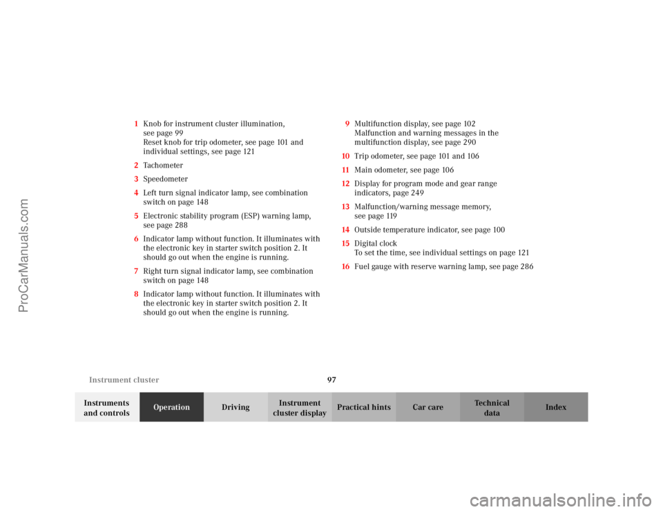
1
Knob for instrument cluster illumination,
seepage99
Reset knob for trip odometer, see page 101 and
individual settings, see page 121
2 Tachometer
3 Speedometer
4 Left turn signal indicator lamp, see combination
switch on page 148
5 Electronic stability program (ESP) warning lamp,
see page 288
6 Indicator lamp without function. It illuminates with
the electronic key in starter switch position 2. It
should go out when the engine is running.
7 Right turn signal indicator lamp, see combination
switch on page 148
8 Indicator lamp without function. It illuminates with
the electronic key in starter switch position 2. It
should go out when the engine is running. 9
Multifunction display, see page 102
Malfunction and warning messages in the
multifunction display, see page 290
10 Trip odometer, see page 101 and 106
11 Main odometer, see page 106
12 Display for program mode and gear range
indicators, page 249
13 Malfunction/warning message memory,
seepage119
14 Outside temperature indicator, see page 100
15 Digital clock
To set the time, see individual settings on page 121
16 Fuel gauge with reserve warning lamp, see page 286
ProCarManuals.com
Page 102 of 399
99
Instrument cluster
Te ch n i c a l
data
Instruments
and controls Operation
DrivingInstrument
cluster display Practical hints Car care Index
Activating instrument cluster display
The instrument cluster is activated by:
• Opening the door
1.
• Pressing button (1) on the instrument cluster
1.
• Turning the electronic key in starter switch to
position 1 or 2.
• Switching on the exterior lamps.
Instrument cluster illumination
The instrument cluster illumination is dimmed or
brightened automatically to suit daylight lighting
conditions.
The instrument cluster illumination will also be
adjusted when the vehicle’s exterior lamps are switched
on.
1 The instrument cluster is activated for approximately 30 seconds.
Display illumination, changing basic settings for driving
at dusk or in darkness:
Rotate adjusting knob (1) clockwise – instrument lamp
intensity increases.
Rotate adjusting knob (1) counterclockwise –
instrument lamp intensity decreases.
Note:
It is not possible to select a basic brightness setting in
daylight – the intensity is adjusted automatically.
ProCarManuals.com