brake MERCEDES-BENZ C-CLASS 2002 Owners Manual
[x] Cancel search | Manufacturer: MERCEDES-BENZ, Model Year: 2002, Model line: C-CLASS, Model: MERCEDES-BENZ C-CLASS 2002Pages: 399, PDF Size: 16.95 MB
Page 6 of 399

3
Contents Maintenance ................................... 227
Tele Aid............................................ 228
Catalytic converter......................... 238
Emission control ............................ 239
Starter switch ................................. 240
Starting and turning off
the engine .................................. 242
Manual transmission .................... 244
Automatic transmission................ 246
Parking brake ................................. 256
Driving instructions ...................... 257 Drive sensibly – Save Fuel........ 257
Drinking and driving................. 257
Pedals ........................................... 257
Power assistance ........................ 258
Brakes .......................................... 258
Driving off ................................... 259
Parking ........................................ 260
Tires ............................................. 261
Snow chains ................................ 263
Winter driving instructions ...... 264
Deep water .................................. 266
Passenger compartment............ 267
Traveling abroad......................... 267 Cruise control ................................ 268
Brake assist system (BAS)............ 271
Antilock brake system (ABS)....... 272
Electronic stability program
(ESP) ........................................... 274
What you should know at the gas station ...................... 278
Check regularly and before a long trip .................................. 280
Instrument cluster displayMalfunction and indicator
lamps in the instrument
cluster......................................... 282
On-board diagnostic system......... 283 Check engine malfunction
indicator lamp ............................ 283
Brake warning lamp .................. 284
Supplemental restraint
system (SRS) indicator lamp .... 285
Fuel reserve warning ................ 286
ABS malfunction indicator
lamp ............................................. 287 Electronic stability program
(ESP) — warning lamp ............... 288
Seat belt nonusage warning lamp ............................................288
Malfunction and indicator lamp in the center console ...... 289
AIRBAG OFF indicator lamp..... 289
Malfunction and warning messages in the
multifunction display ............... 290
DISPLAY DEFECTIVE ................ 291
BATTERY / ALTERNATOR........ 292
ANTILOCK BRAKE SYSTEM..... 293
BRAKE ASSIST ........................... 293
BRAKE PAD WEAR .................... 294
BRAKE FLUID ............................. 294
PARKING BRAKE ....................... 295
SEAT BELT SYSTEM................... 295
ELEC. STABIL. PROG.
(Electronic stability program) .. 296
COOLANT (coolant level) .......... 297
COOLANT
(coolant temperature) ................ 298
ENGINE OIL LEVEL ................... 299
ProCarManuals.com
Page 8 of 399

5
Contents Light alloy wheels ...................... 364
Instrument cluster ..................... 364
Steering wheel and
gear selector lever ......................364
Cup holder................................... 364
Seat belts ..................................... 365
Headliner and shelf below
rear window ................................ 365
Leather upholstery ..................... 365
Hard plastic trim items ............. 365
Plastic and rubber parts............ 365
Technical dataSpare parts service ........................ 368
Warranty coverage ......................... 368
Identification labels....................... 369
Layout of poly-V-belt drive............ 371
Technical data................................. 373
Fuels, coolants, lubricants etc. -
capacities ................................... 377
Engine oils ...................................... 379
Engine oil additives ....................... 379
Air conditioner refrigerant........... 379
Brake fluid ...................................... 379 Premium unleaded gasoline ........ 380
Fuel requirements......................... 380
Gasoline additives ......................... 381
Coolants .......................................... 381
Consumer information ................. 383
Uniform tire quality grading ....... 383
IndexIndex ............................................... 385
ProCarManuals.com
Page 26 of 399

23
Instruments and controls
Te ch n i c a l
data
Instruments
and controls Operation Driving
Instrument
cluster display Practical hints Car care Index
1
Hood lock release, see page 315
2 Parking brake pedal, see page 256
3 Steering wheel adjustment (manual), see page 87
4 Parking brake release, see page 256
5 Exterior lamp switch, see page 143
6 Combination switch, see page 148
7 Exterior mirror adjustment switch, see page 90
8 Headlamp washer button, see page 147
9 Cruise control switch, see page 268 10
Multifunction steering wheel, see page 102
Horn (with electronic key in starter switch
position 1 or 2)
11 Instrument cluster, see page 96
12 Voice recognition system switch (optional), see
separate operating instructions
13 Starter switch, see page 240
14 Glove box lid release, see page 207
15 Glove box lock, see page 207
ProCarManuals.com
Page 52 of 399

49
Seats
Te ch n i c a l
data
Instruments
and controls Operation
DrivingInstrument
cluster display Practical hints Car care Index
Power seat
(optional)
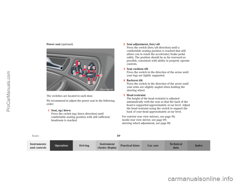
The switches are located in each door.
We recommend to adjust the power seat in the following
order: 1 Seat, up / down
Press the switch (up / down direction) until
comfortable seating position with still sufficient
headroom is reached. 2
Seat adjustment, fore / aft
Press the switch (fore / aft direction) until a
comfortable seating position is reached that still
allows you to reach the accelerator / brake pedal
safely. The position should be as far rearward as
possible, consistent with ability to properly operate
controls.
3 Seat cushion tilt
Press the switch in the direction of the arrow until
your legs are lightly supported.
4 Backrest tilt
Press the switch in the direction of the arrow until
your arms are slightly angled when holding the
steering wheel.
5 Head restraint
The height of the head restraint is adjusted
automatically with the seat so that the back of the
head is supported approximately at ear level. Adjust
the head restraint using the switch to support the
back of your head approximately at ear level.
For exterior rear view mirrors, see page 90;
inside rear view mirror, see page 89;
steering wheel adjustment, see page 88.
ProCarManuals.com
Page 101 of 399

98
Instrument cluster
Te ch n i c a l
data
Instruments
and controls Operation
DrivingInstrument
cluster display Practical hints Car care Index
Indicator lamps in the instrument cluster High beam, see page 148
ABS malfunction, see page 287
Brake fluid low (except Canada).
Parking brake engaged, see page 284
ESP. Adjust driving to road condition,
see page 288
Fasten seat belts, see page 288
SRS malfunction, see page 285 Engine malfunction indicator lamp. If the
malfunction indicator lamp comes on when
the engine is running, it indicates a
malfunction of the fuel management system,
emission control system, systems which
impact emissions, or the fuel cap is not
closed tight. In all cases, we recommend that
you have the malfunction checked as soon as
possible, see page 283
ABS
ProCarManuals.com
Page 214 of 399

211
Interior equipment
Te ch n i c a l
data
Instruments
and controls Operation
DrivingInstrument
cluster display Practical hints Car care Index
Ashtrays
Center console
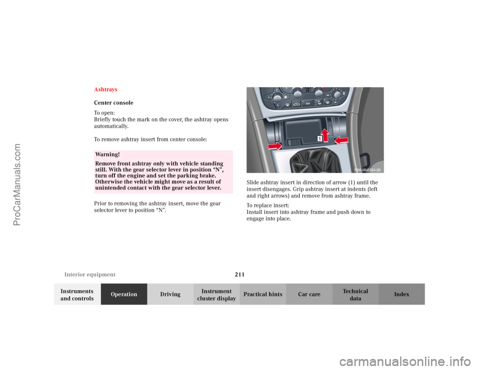
To o pen :
Briefly touch the mark on the cover, the ashtray opens
automatically.
To remove ashtray insert from center console:
Prior to removing the ashtray insert, move the gear
selector lever to position “N”.
Slide ashtray insert in direction of arrow (1) until the
insert disengages. Grip ashtray insert at indents (left
and right arrows) and remove from ashtray frame.
To replace insert:
Install insert into ashtray frame and push down to
engage into place.
Wa r n i n g !
Remove front ashtray only with vehicle standing
still. With the gear selector lever in position “N”,
turn off the engine and set the parking brake.
Otherwise the vehicle might move as a result of
unintended contact with the gear selector lever.
ProCarManuals.com
Page 228 of 399

225
Contents - Driving
Te ch n i c a l
data
Instruments
and controls Operation
DrivingInstrument
cluster display Practical hints Car care Index
DrivingControl and operation of
radio transmitters ..................... 226
The first 1 000 miles (1 500 km) ................................. 227
Maintenance ................................... 227
Tele Aid............................................ 228
Catalytic converter......................... 238
Emission control ............................ 239
Starter switch ................................. 240
Starting and turning off the engine .................................. 242
Manual transmission .................... 244
Automatic transmission................ 246 Parking brake ................................ 256
Driving instructions...................... 257
Drive sensibly – Save Fuel ....... 257
Drinking and driving ................ 257
Pedals .......................................... 257
Power assistance........................ 258
Brakes .......................................... 258
Driving off................................... 259
Parking ........................................ 260
Tires ............................................. 261
Snow chains................................ 263
Winter driving instructions ..... 264
Deep water .................................. 266
Passenger compartment ........... 267
Traveling abroad ........................ 267 Cruise control ................................. 268
Brake assist system (BAS) ............ 271
Antilock brake system (ABS) ....... 272
Electronic stability program
(ESP) ........................................... 274
What you should know at the gas station ....................... 278
Check regularly and before a long trip ................................... 280
ProCarManuals.com
Page 230 of 399

227
The first 1 000 miles
Te ch n i c a l
data
Instruments
and controls Operation
DrivingInstrument
cluster display Practical hints Car care Index
The first 1 000 miles (1 500 km)
The more cautiously you treat your vehicle during the
break-in period, the more satisfied you will be with its
performance later on. Therefore, drive your vehicle
during the first 1 000 miles (1 500 km) at moderate
vehicle and engine speeds.
During this period, avoid heavy loads (full throttle
driving) and excessive engine speeds.
Avoid accelerating by kickdown. It is not recommended
to brake the vehicle by manually shifting to a lower gear.
We recommend that you select positions “3”, “2” or “1”
only at moderate speeds (for hill driving).
After 1 000 miles (1 500 km) speeds may be gradually
increased to the permissible maximum.
Maintenance
We strongly recommend that you have your vehicle
serviced by your authorized Mercedes-Benz Center, in
accordance with the Service Booklet at the times called
for by the FSS.
Failure to have the vehicle maintained in accordance
with the Service Booklet at the designated times /
mileage may result in vehicle damage not covered by
the Mercedes-Benz Limited Warranty.
For information on the Flex
ible service system (FSS),
see page 138.
ProCarManuals.com
Page 243 of 399

240
Starter switch
Te ch n i c a l
data
Instruments
and controls Operation
DrivingInstrument
cluster display Practical hints Car care Index
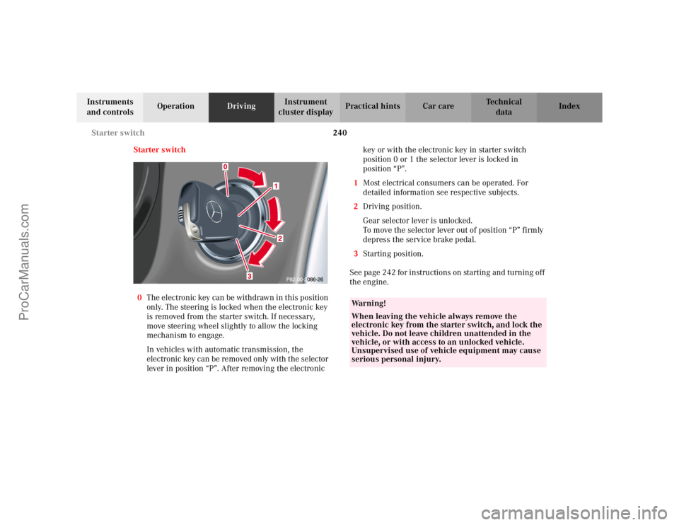
Starter switch
0 The electronic key can be withdrawn in this position
only. The steering is locked when the electronic key
is removed from the starter switch. If necessary,
move steering wheel slightly to allow the locking
mechanism to engage.
In vehicles with automatic transmission, the
electronic key can be removed only with the selector
lever in position “P”. After removing the electronic key or with the electronic key in starter switch
position 0 or 1 the selector lever is locked in
position “P”.
1 Most electrical consumers can be operated. For
detailed information see respective subjects.
2 Driving position.
Gear selector lever is unlocked.
To move the selector lever out of position “P” firmly
depress the service brake pedal.
3 Starting position.
See page 242 for instructions on starting and turning off
the engine.
Wa r n i n g !
When leaving the vehicle always remove the
electronic key from the starter switch, and lock the
vehicle. Do not leave children unattended in the
vehicle, or with access to an unlocked vehicle.
Unsupervised use of vehicle equipment may cause
serious personal injury.
ProCarManuals.com
Page 245 of 399

242
Starting and turning off the engine
Te ch n i c a l
data
Instruments
and controls Operation
DrivingInstrument
cluster display Practical hints Car care Index
Starting and turning off the engine
Before starting
Ensure that parking brake is engaged and that selector
lever is in position “P” or “N” (gearshift lever in
neutral). Turn electronic key in starter switch to
position 2.
Starting
Vehicles with automatic transmission:
Do not depress accelerator. Briefly turn electronic key in
starter switch clockwise to the stop and release. The
starter will engage until the engine is running.
If engine will not run, and the starting procedure stops,
turn electronic key completely to the left and repeat
starting the engine.
After several unsuccessful attempts, have the system
checked at the nearest authorized Mercedes-Benz
Center. Vehicles with manual transmission:
Do not depress accelerator. Fully depress clutch pedal,
otherwise the engine cannot be started due to the
integrated safety interlock.
Turn electronic key in starter switch clockwise to the
stop. Release only when the engine is firing regularly.
ProCarManuals.com