Aps MERCEDES-BENZ C-Class 2011 W204 Owner's Manual
[x] Cancel search | Manufacturer: MERCEDES-BENZ, Model Year: 2011, Model line: C-Class, Model: MERCEDES-BENZ C-Class 2011 W204Pages: 320, PDF Size: 13.17 MB
Page 61 of 320
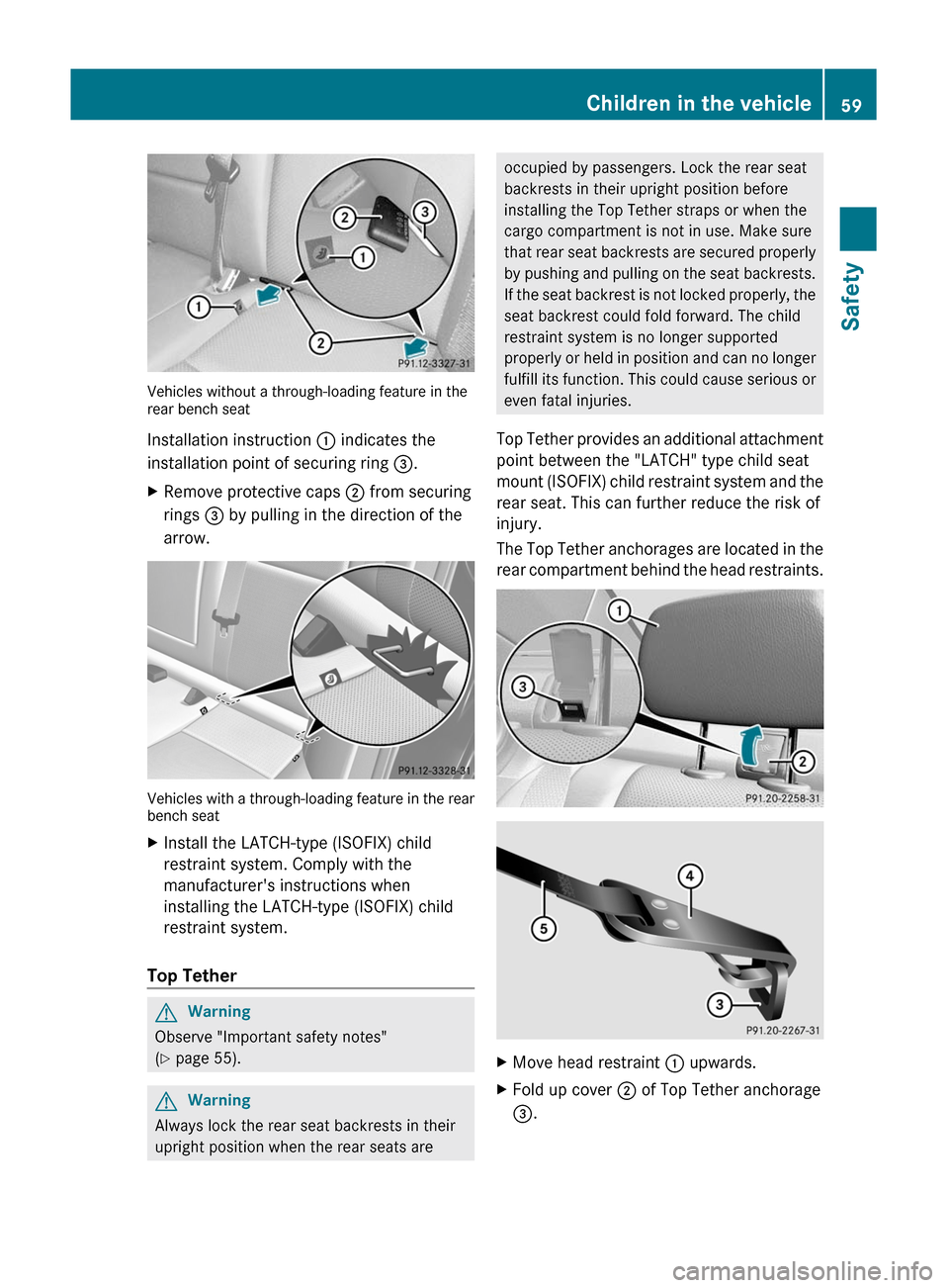
Vehicles without a through-loading feature in the
rear bench seat
Installation instruction : indicates the
installation point of securing ring =.
XRemove protective caps ; from securing
rings = by pulling in the direction of the
arrow.
Vehicles with a through-loading feature in the rear
bench seat
XInstall the LATCH-type (ISOFIX) child
restraint system. Comply with the
manufacturer's instructions when
installing the LATCH-type (ISOFIX) child
restraint system.
Top Tether
GWarning
Observe "Important safety notes"
( Y page 55).
GWarning
Always lock the rear seat backrests in their
upright position when the rear seats are
occupied by passengers. Lock the rear seat
backrests in their upright position before
installing the Top Tether straps or when the
cargo compartment is not in use. Make sure
that rear seat backrests are secured properly
by pushing and pulling on the seat backrests.
If the seat backrest is not locked properly, the
seat backrest could fold forward. The child
restraint system is no longer supported
properly or held in position and can no longer
fulfill its function. This could cause serious or
even fatal injuries.
Top Tether provides an additional attachment
point between the "LATCH" type child seat
mount (ISOFIX) child restraint system and the
rear seat. This can further reduce the risk of
injury.
The Top Tether anchorages are located in the
rear compartment behind the head restraints.XMove head restraint : upwards.XFold up cover ; of Top Tether anchorage
= .Children in the vehicle59SafetyBA 204 USA, CA Edition A 2011; 1; 5, en-UShereepeVersion: 3.0.3.62010-05-20T09:17:30+02:00 - Seite 59Z
Page 157 of 320
ROnly use snow chains when driving on an
area completely covered by snow. Do not
exceed the maximum permissible speed of
30 mph (50 km/h). Remove the snow
chains as soon as possible when you are no
longer driving on snow-covered roads.
R Local regulations may restrict the use of
snow chains. Applicable regulations must
be observed if you wish to mount snow
chains.
R Snow chains must not be mounted on
emergency spare wheels.
If you intend to mount snow chains, please
bear the following points in mind:
R you may not attach snow chains to all
wheel-tire combinations; see the "Tires and
wheels" section in the "Technical data"
chapter.
R mount snow chains only in pairs and only
on the rear wheels. Observe the
manufacturer's installation instructions.
! If snow chains are mounted on the front
wheels, the snow chains could grind
against the bodywork or components of the
chassis. This could result in damage to the
vehicle or the tires.
! Vehicles with steel wheels
If you wish to mount snow chains to steel
wheels, make sure that you remove the
respective wheels' hubcaps first. The
hubcaps may otherwise be damaged.
i You may wish to deactivate
ESP ®
(Y page 63) when pulling away with
snow chains installed. This way you can
allow the wheels to spin in a controlled
manner, achieving an increased driving
force (cutting action).
Slippery road surfacesGWarning
If the vehicle becomes stuck in snow, make
sure snow is kept clear of the exhaust pipe
and from around the vehicle with the engine
running. Otherwise, deadly carbon monoxide
(CO) gases may enter vehicle interior
resulting in unconsciousness and death.
To assure sufficient fresh air ventilation, open
a window slightly on the side of the vehicle
not facing the wind.GWarning!
The outside temperature indicator is not
designed to serve as an ice-warning device
and is therefore unsuitable for that purpose.
Indicated temperatures just above the
freezing point do not guarantee that the road
surface is free of ice. The road may still be icy,
especially in wooded areas or on bridges.
GWarning
On slippery road surfaces, never downshift in
order to obtain braking action. This could
result in drive wheel slip and reduced vehicle
control. Your vehicle's ABS will not prevent
this type of loss of control.
You should drive particularly carefully on
slippery road surfaces. Avoid sudden
acceleration, steering and braking
maneuvers. Do not use cruise control.
If the vehicle threatens to skid or cannot be
stopped when moving at low speed:
XVehicles with manual transmission: engage
neutral.XVehicles with automatic transmission: shift
the transmission to position N.
i
For more information on driving with
snow chains, see ( Y page 154).
GWarning
Make sure that you do not endanger other
road users when you apply the brakes.
Driving abroad
An extensive Mercedes-Benz Service network
is also available in other countries. The
Service Hotline's current telephone numbers
for use when you are abroad are to be found
Driving tips155Driving and parkingBA 204 USA, CA Edition A 2011; 1; 5, en-UShereepeVersion: 3.0.3.62010-05-20T09:17:30+02:00 - Seite 155Z
Page 174 of 320
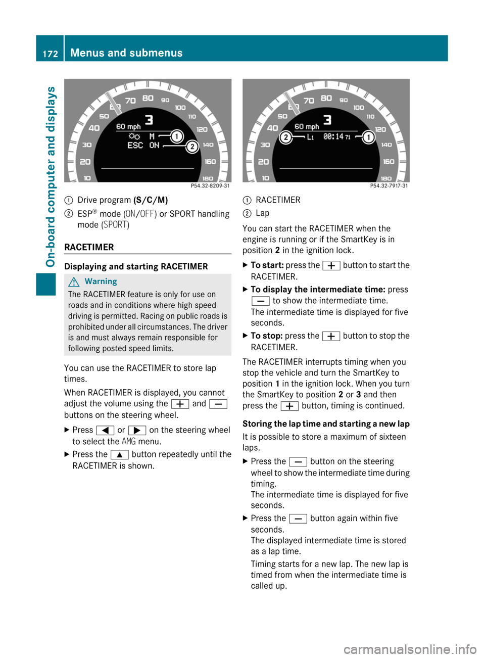
:Drive program (S/C/M);ESP®
mode ( ON/OFF ) or SPORT handling
mode ( SPORT)
RACETIMER
Displaying and starting RACETIMER
GWarning
The RACETIMER feature is only for use on
roads and in conditions where high speed
driving is permitted. Racing on public roads is
prohibited under all circumstances. The driver
is and must always remain responsible for
following posted speed limits.
You can use the RACETIMER to store lap
times.
When RACETIMER is displayed, you cannot
adjust the volume using the W and X
buttons on the steering wheel.
XPress = or ; on the steering wheel
to select the AMG menu.XPress the 9 button repeatedly until the
RACETIMER is shown.:RACETIMER;Lap
You can start the RACETIMER when the
engine is running or if the SmartKey is in
position 2 in the ignition lock.
XTo start: press the W button to start the
RACETIMER.XTo display the intermediate time: press
X to show the intermediate time.
The intermediate time is displayed for five
seconds.XTo stop: press the W button to stop the
RACETIMER.
The RACETIMER interrupts timing when you
stop the vehicle and turn the SmartKey to
position 1 in the ignition lock. When you turn
the SmartKey to position 2 or 3 and then
press the W button, timing is continued.
Storing the lap time and starting a new lap
It is possible to store a maximum of sixteen
laps.
XPress the X button on the steering
wheel to show the intermediate time during
timing.
The intermediate time is displayed for five
seconds.XPress the X button again within five
seconds.
The displayed intermediate time is stored
as a lap time.
Timing starts for a new lap. The new lap is
timed from when the intermediate time is
called up.172Menus and submenusOn-board computer and displays
BA 204 USA, CA Edition A 2011; 1; 5, en-UShereepeVersion: 3.0.3.62010-05-20T09:17:30+02:00 - Seite 172
Page 175 of 320
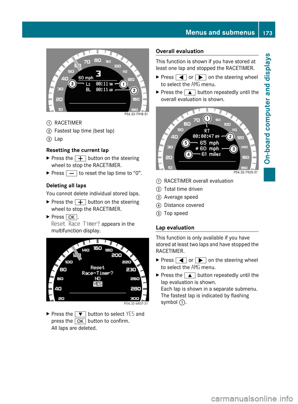
:RACETIMER;Fastest lap time (best lap)=Lap
Resetting the current lap
XPress the W button on the steering
wheel to stop the RACETIMER.
XPress X to reset the lap time to "0”.
Deleting all laps
You cannot delete individual stored laps.
XPress the W button on the steering
wheel to stop the RACETIMER.
XPress a.
Reset Race Timer? appears in the
multifunction display.
XPress the : button to select YES and
press the a button to confirm.
All laps are deleted.
Overall evaluation
This function is shown if you have stored at
least one lap and stopped the RACETIMER.
XPress = or ; on the steering wheel
to select the AMG menu.
XPress the 9 button repeatedly until the
overall evaluation is shown.
:RACETIMER overall evaluation;Total time driven=Average speed?Distance coveredATop speed
Lap evaluation
This function is only available if you have
stored at least two laps and have stopped the
RACETIMER.
XPress = or ; on the steering wheel
to select the AMG menu.
XPress the 9 button repeatedly until the
lap evaluation is shown.
Each lap is shown in a separate submenu.
The fastest lap is indicated by flashing
symbol :.
Menus and submenus173On-board computer and displaysBA 204 USA, CA Edition A 2011; 1; 5, en-UShereepeVersion: 3.0.3.62010-05-20T09:17:30+02:00 - Seite 173Z
Page 219 of 320
devices; see separate COMAND operating
instructions.
iThe glove box can be ventilated
(Y page 127).
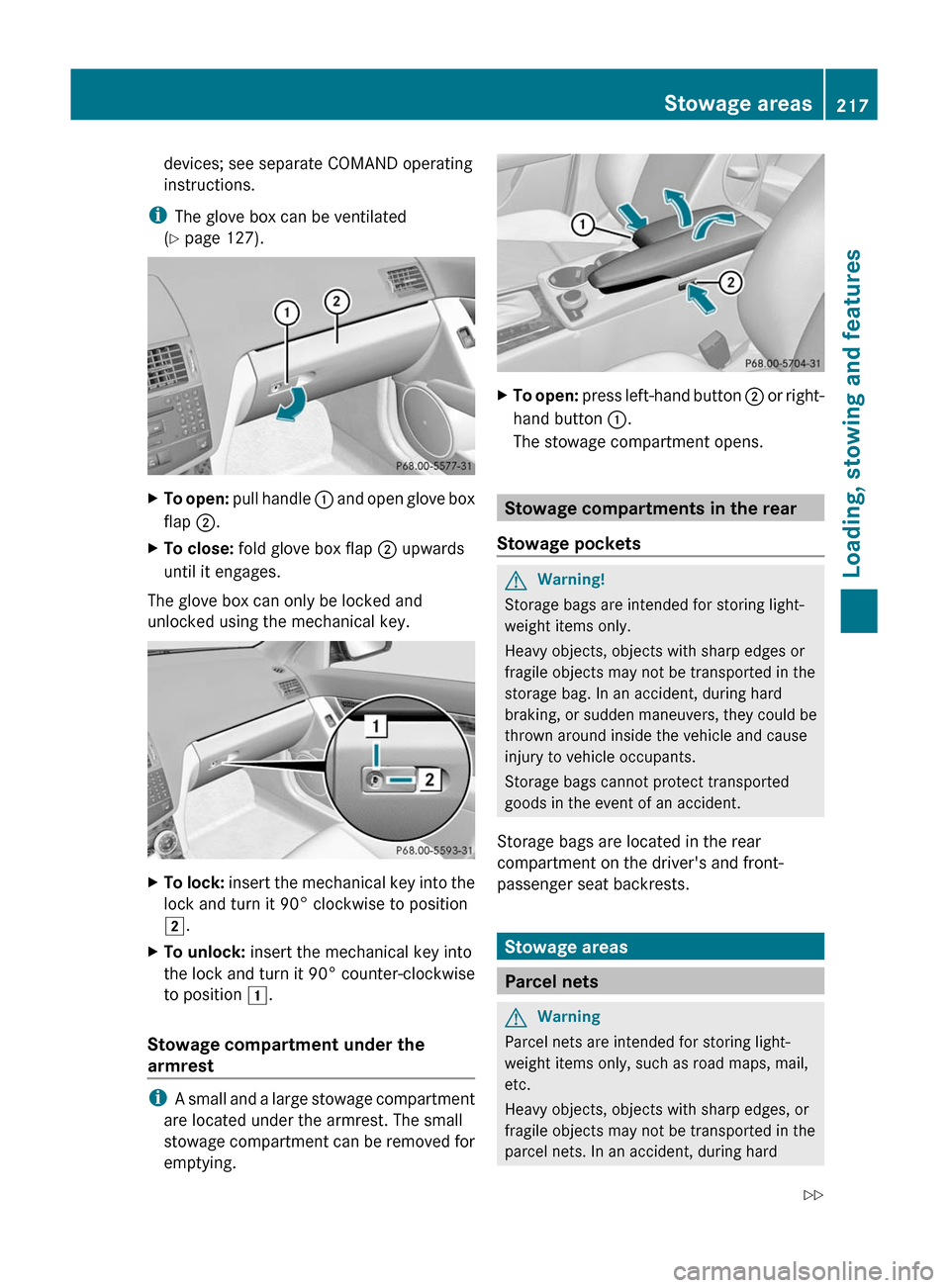
XTo open: pull handle : and open glove box
flap ;.
XTo close: fold glove box flap ; upwards
until it engages.
The glove box can only be locked and
unlocked using the mechanical key.
XTo lock: insert the mechanical key into the
lock and turn it 90° clockwise to position
2.
XTo unlock: insert the mechanical key into
the lock and turn it 90° counter-clockwise
to position 1.
Stowage compartment under the
armrest
iA small and a large stowage compartment
are located under the armrest. The small
stowage compartment can be removed for
emptying.
XTo open: press left-hand button ; or right-
hand button :.
The stowage compartment opens.
Stowage compartments in the rear
Stowage pockets
GWarning!
Storage bags are intended for storing light-
weight items only.
Heavy objects, objects with sharp edges or
fragile objects may not be transported in the
storage bag. In an accident, during hard
braking, or sudden maneuvers, they could be
thrown around inside the vehicle and cause
injury to vehicle occupants.
Storage bags cannot protect transported
goods in the event of an accident.
Storage bags are located in the rear
compartment on the driver's and front-
passenger seat backrests.
Stowage areas
Parcel nets
GWarning
Parcel nets are intended for storing light-
weight items only, such as road maps, mail,
etc.
Heavy objects, objects with sharp edges, or
fragile objects may not be transported in the
parcel nets. In an accident, during hard
Stowage areas217Loading, stowing and featuresBA 204 USA, CA Edition A 2011; 1; 5, en-UShereepeVersion: 3.0.3.62010-05-20T09:17:30+02:00 - Seite 217Z
Page 221 of 320
occupied, or the extended cargo volume is not
in use.
Check for secure locking by pushing and
pulling on the seat backrest.
In an accident, during hard braking or sudden
maneuvers, loose items will be thrown around
inside the vehicle. This can cause injury to
vehicle occupants unless the items are
securely fastened in the vehicle.
To help avoid personal injury during a collision
or sudden maneuver, exercise care when
transporting cargo.
iYou should always engage the rear seat
backrests if you do not need the through-
loading feature. This will prevent
unauthorized access to the trunk from the
vehicle interior.
XAdjust the head restraints if necessary
(Y page 96).
XMove the driver's or front-passenger seat
back if necessary.
Securing cargos
Lashing eyelets
Observe the following notes on securing
loads:
Rsecure the load using the cargo tie down
rings.
Rdo not use elastic straps or nets to secure
a load, as these are only intended as an
anti-slip protection for light loads.
Rdo not route tie downs across sharp edges
or corners.
Rpad sharp edges for protection.
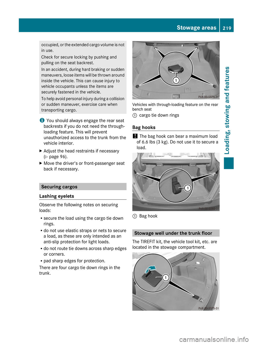
There are four cargo tie down rings in the
trunk.
Vehicles with through-loading feature on the rearbench seat
:cargo tie down rings
Bag hooks
! The bag hook can bear a maximum load
of 6.6 lbs (3 kg). Do not use it to secure a
load.
:Bag hook
Stowage well under the trunk floor
The TIREFIT kit, the vehicle tool kit, etc. are
located in the stowage compartment.
Stowage areas219Loading, stowing and featuresBA 204 USA, CA Edition A 2011; 1; 5, en-UShereepeVersion: 3.0.3.62010-05-20T09:17:30+02:00 - Seite 219Z
Page 235 of 320
of the garage door. People could otherwise be
injured by the movement of the door.
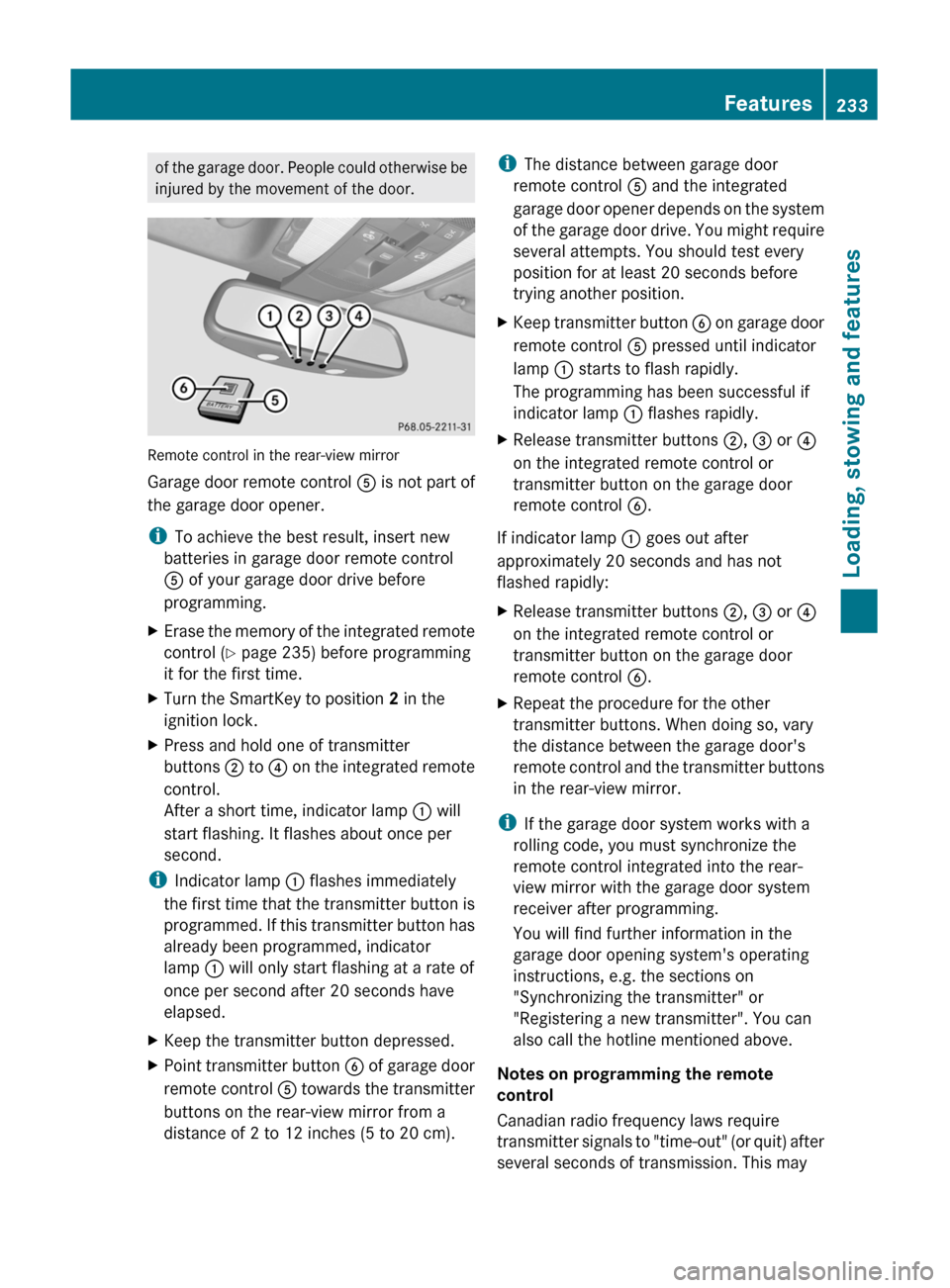
Remote control in the rear-view mirror
Garage door remote control A is not part of
the garage door opener.
i To achieve the best result, insert new
batteries in garage door remote control
A of your garage door drive before
programming.
XErase the memory of the integrated remote
control ( Y page 235) before programming
it for the first time.XTurn the SmartKey to position 2 in the
ignition lock.XPress and hold one of transmitter
buttons ; to ? on the integrated remote
control.
After a short time, indicator lamp : will
start flashing. It flashes about once per
second.
i Indicator lamp : flashes immediately
the first time that the transmitter button is
programmed. If this transmitter button has
already been programmed, indicator
lamp : will only start flashing at a rate of
once per second after 20 seconds have
elapsed.
XKeep the transmitter button depressed.XPoint transmitter button B of garage door
remote control A towards the transmitter
buttons on the rear-view mirror from a
distance of 2 to 12 inches (5 to 20 cm).i The distance between garage door
remote control A and the integrated
garage door opener depends on the system
of the garage door drive. You might require
several attempts. You should test every
position for at least 20 seconds before
trying another position.XKeep transmitter button B on garage door
remote control A pressed until indicator
lamp : starts to flash rapidly.
The programming has been successful if
indicator lamp : flashes rapidly.XRelease transmitter buttons ;, = or ?
on the integrated remote control or
transmitter button on the garage door
remote control B.
If indicator lamp : goes out after
approximately 20 seconds and has not
flashed rapidly:
XRelease transmitter buttons ;, = or ?
on the integrated remote control or
transmitter button on the garage door
remote control B.XRepeat the procedure for the other
transmitter buttons. When doing so, vary
the distance between the garage door's
remote control and the transmitter buttons
in the rear-view mirror.
i If the garage door system works with a
rolling code, you must synchronize the
remote control integrated into the rear-
view mirror with the garage door system
receiver after programming.
You will find further information in the
garage door opening system's operating
instructions, e.g. the sections on
"Synchronizing the transmitter" or
"Registering a new transmitter". You can
also call the hotline mentioned above.
Notes on programming the remote
control
Canadian radio frequency laws require
transmitter signals to "time-out" (or quit) after
several seconds of transmission. This may
Features233Loading, stowing and featuresBA 204 USA, CA Edition A 2011; 1; 5, en-UShereepeVersion: 3.0.3.62010-05-20T09:17:30+02:00 - Seite 233Z
Page 237 of 320
Clearing the remote control memoryXTurn the SmartKey to position 2 in the
ignition lock.XPress and hold transmitter buttons ;
and ? for approximately 20 seconds until
indicator lamp : flashes rapidly.
The memory is cleared.
i You should clear the remote control
memory before selling the vehicle.
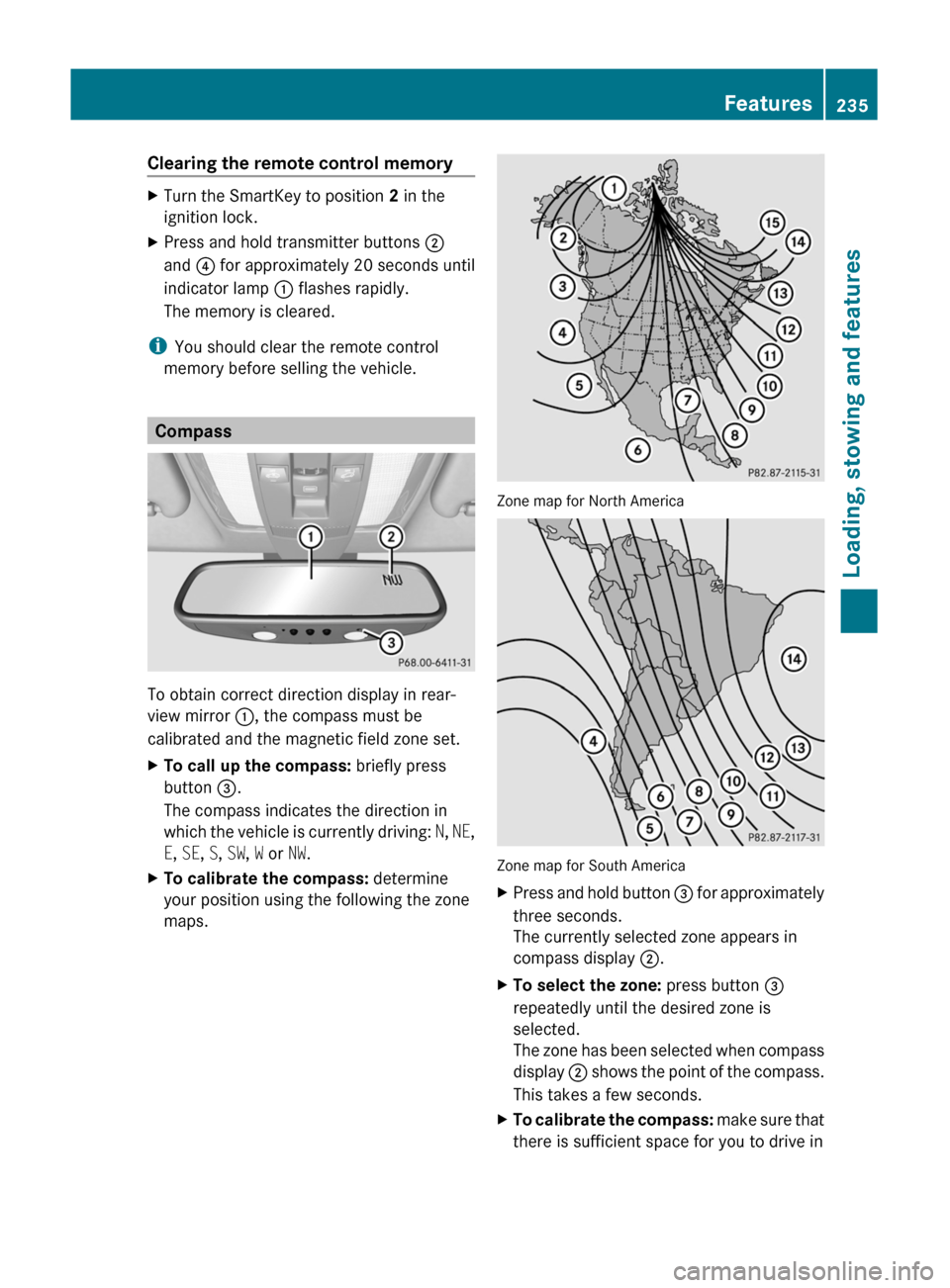
Compass
To obtain correct direction display in rear-
view mirror :, the compass must be
calibrated and the magnetic field zone set.
XTo call up the compass: briefly press
button =.
The compass indicates the direction in
which the vehicle is currently driving: N, NE ,
E , SE , S , SW , W or NW.XTo calibrate the compass: determine
your position using the following the zone
maps.
Zone map for North America
Zone map for South America
XPress and hold button = for approximately
three seconds.
The currently selected zone appears in
compass display ;.XTo select the zone: press button =
repeatedly until the desired zone is
selected.
The zone has been selected when compass
display ; shows the point of the compass.
This takes a few seconds.XTo calibrate the compass: make sure that
there is sufficient space for you to drive inFeatures235Loading, stowing and featuresBA 204 USA, CA Edition A 2011; 1; 5, en-UShereepeVersion: 3.0.3.62010-05-20T09:17:30+02:00 - Seite 235Z
Page 260 of 320
Mounting a new wheelGWarning!
Always replace wheel bolts that are damaged
or rusted.
Never apply oil or grease to wheel bolts.
Damaged wheel hub threads should be
repaired immediately. Do not continue to
drive under these circumstances! Contact an
authorized Mercedes-Benz Center or call
Roadside Assistance.
Incorrect wheel bolts or improperly tightened
wheel bolts can cause the wheel to come off.
This could cause an accident. Make sure to
use the correct wheel bolts.
GWarning
Only use genuine Mercedes-Benz wheel bolts.
Other wheel bolts may come loose.
Do not tighten the wheel bolts when the
vehicle is raised. Otherwise, the vehicle could
fall off the jack.
GWarning
Make sure to use the original length wheel
bolts when remounting the original wheel
after it has been repaired.
XClean the wheel and wheel hub contact
surfaces.
! To prevent damage to the paintwork, hold
the wheel securely against the wheel hub
while screwing in the first wheel bolt.
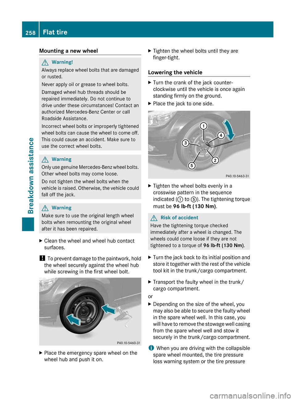
XPlace the emergency spare wheel on the
wheel hub and push it on.XTighten the wheel bolts until they are
finger-tight.
Lowering the vehicle
XTurn the crank of the jack counter-
clockwise until the vehicle is once again
standing firmly on the ground.XPlace the jack to one side.XTighten the wheel bolts evenly in a
crosswise pattern in the sequence
indicated ( : to A). The tightening torque
must be 96 lb-ft (130 Nm) .GRisk of accident
Have the tightening torque checked
immediately after a wheel is changed. The
wheels could come loose if they are not
tightened to a torque of 96 lb-ft (130 Nm).
XTurn the jack back to its initial position and
store it together with the rest of the vehicle
tool kit in the trunk/cargo compartment.XTransport the faulty wheel in the trunk/
cargo compartment.
or
XDepending on the size of the wheel, you
may also be able to secure the faulty wheel
in the spare wheel well. In this case, you
will have to remove the stowage well casing
from the spare wheel well and stow it
securely in the trunk/cargo compartment.
i When you are driving with the collapsible
spare wheel mounted, the tire pressure
loss warning system or the tire pressure
258Flat tireBreakdown assistance
BA 204 USA, CA Edition A 2011; 1; 5, en-UShereepeVersion: 3.0.3.62010-05-20T09:17:30+02:00 - Seite 258
Page 273 of 320
Directives to be observed
R Only mount tires and wheels of the same
type and make.
R Only mount tires of the correct size onto
the wheels.
R After mounting new tires, run them in at
moderate speeds for the first 60 miles
(100 km) as they only reach their full
performance after this distance.
R Do not use tires until they are excessively
worn as the tire traction on wet road
surfaces decreases significantly when the
tread depth is less than 1
/ 8 in (3 mm).
R If the vehicle is heavily laden, check the tire
pressure and adjust it if necessary.
R When parking your vehicle, make sure that
the tires do not get deformed by the curb
or other obstacles. If it is necessary to drive
over curbs, speed humps or similar
elevations, try to do so slowly and at an
obtuse angle. Otherwise, the tires,
particularly the sidewalls, can get
damaged.
Maintenance and care of wheels and
tires
Checking wheels and tires
GWarning
Regularly check the tires for damage.
Damaged tires can cause tire inflation
pressure loss. As a result, you could lose
control of your vehicle.
Worn, old tires can cause accidents. If the tire
tread is worn to minimum tread depth, or if
the tires have sustained damage, replace
them.
R Regularly check the wheels and tires of
your vehicle for damage (e.g. cuts,
punctures, tears, bulges on tires and
deformation or cracks or severe corrosion
on wheels), at least once a month, as well
as after driving off-road or on rough roads.
Damaged wheels can cause a loss of tire
pressure.
R Regularly check the tire tread depth and
the condition of the tread across the whole
width of the tire (Y page 271). If necessary,
turn the front wheels to full lock in order to
inspect the inner side of the tire surface.
R All wheels must have a valve cap to protect
the valve against dirt and moisture. Do not
install anything on the valve (such as tire
pressure monitoring systems) other than
the standard valve cap or other valve caps
approved by Mercedes-Benz for your
vehicle.
R Regularly check the pressure of all the tires
including the emergency spare wheel or the
spare wheel, particularly prior to long trips,
and correct the pressure as necessary
( Y page 272).
Service life of tires
The service life of tires depends on the
following factors amongst other things:
R driving style
R tire pressure
R mileage
Replace the tires after six years at the latest,
regardless of wear. This also applies to the
emergency spare wheel/spare wheel.
Tire tread
GWarning
Although the applicable federal motor vehicle
safety laws consider a tire to be worn when
the tread wear indicators (TWI) become
visible at approximately 1
/ 16 in (1.6 mm), we
recommend that you do not allow your tires
to wear down to that level. As tread depth
approaches 1
/ 8 in (3 mm), the adhesion
properties on a wet road are sharply reduced.
Maintenance and care of wheels and tires271Tires and wheelsBA 204 USA, CA Edition A 2011; 1; 5, en-UShereepeVersion: 3.0.3.62010-05-20T09:17:30+02:00 - Seite 271Z