fuse MERCEDES-BENZ C CLASS 2016 Owners Manual
[x] Cancel search | Manufacturer: MERCEDES-BENZ, Model Year: 2016, Model line: C CLASS, Model: MERCEDES-BENZ C CLASS 2016Pages: 398, PDF Size: 11.64 MB
Page 13 of 398
Problem (malfunction) .................. .1 68
Refueling ........................................ 164
Tank content/reserve fuel ............. 389
Fuel filler flap
Opening ......................................... 165
Fuel level
Calling up the range (on-board
computer) ...................................... 240
Fuel tank
Capacity ........................................ 389
Problem (malfunction) ................... 168
Fuses
Allocation chart ..................... 357, 359
Before changing ............................ .3 57
Dashboard fuse box ....................... 357
Fuse box in the engine compart-
ment .............................................. 358
Fuse box in the front-passenger
footwell .......................................... 358
Fuse box in the trunk ..................... 359
Important safety notes .................. 357
G G-Meter (on-board computer,
Mercedes-AMG vehicles) .................. 252
Garage door opener
Clearing the memory ..................... 329
General notes ................................ 326
Important safety notes .................. 327
Opening/closing the garage door .. 329
Problems when programming ....... .3 28
Programming (button in the rear-
view mirror) ................................... 327
Synchronizing the rolling code ....... 328
Gear indicator (on-board com-
puter, Mercedes-AMG vehicles) ....... 252
Genuine parts ...................................... 27
Glove box .......................................... .3 09
Google™ Local Search
see also Digital Operator's Man-
ual ................................................. .2 98
H
Handbrake
see Parking brake
HANDS-FREE ACCESS .......................... 92 Handwriting recognition
Switching text reader function
on/off ............................................ 301
Touchpad ....................................... 300
Hazard warning lamps ..................... .1 20
Head restraints
Adjusting (electrically) ................... 107
Adjusting (manually) ..................... .1 07
Adjusting (rear) .............................. 107
Adjusting the fore-and-aft posi-
tion manually ................................. 107
General notes ................................ 106
Important safety notes .................. 106
Installing/removing (rear) .............. 107
Head-up display
Adjusting the brightness ................ 250
Displays and operating .................. 238
Function/notes ............................ .2 38
Important safety notes .................. 238
Selecting displays .......................... 249
Setting the position ....................... 250
Storing settings (memory func-
tion) ............................................... 116
Headlamps
Cleaning system (notes) ................ 393
Fogging up ..................................... 121
see Automatic headlamp mode
Heating
see Climate control
High beam flasher ............................ .1 19
High-beam headlamps
Adaptive Highbeam Assist ............. 120
Changing bulbs .............................. 124
Display message ............................ 267
Switching on/off ........................... 119
High-voltage battery
Battery care ................................... 170
Charging (charging station) ............ 174
Charging (mains socket) ................ 171
Charging (wallbox) ......................... 173
Charging cable warming ................ 170
Cruise range .................................. 170
Energy consumption ..................... .1 70
General notes .................................. 45
Method of operation ..................... .1 69
Outside temperatures .................... 170
Overvoltage protection .................. 170 Index 11
Page 172 of 398
The high-voltage battery can be charged in a
nominal voltage range from 100 V to 240 V.
You can view the condition of charge of the high-
voltage battery in the multifunction display. You
can find information in "PLUG-IN HYBRID oper-
ation", section "Menus and submenus" under
"Energy flow display" ( Y
page 227).
High and low outside temperatures Low outside temperatures
At very low outside temperatures the maximum
power output of the high-voltage battery may be
reduced. The high-voltage battery is then no
longer able to provide the normal electrical
power output.
High outside temperatures
To prevent damage to the high-voltage battery
due to very high outside temperatures, the max-
imum power output of the high-voltage battery
is reduced by the vehicle.
Energy consumption and electrical
range The maximum electrical range is generally
reduced by: R
high and low outside temperatures R
operating the climate control system R
switching on consumers
The battery's physical characteristics are such
that leaving the vehicle parked for long periods
at low outdoor temperatures without charging it
can lead to: R
a reduction in battery performance R
longer charge times
Notes on battery care Avoid storing or transporting the vehicle at
excessively high or low temperatures over a long
period.
If you park the vehicle and leave it stationary for
long periods: R
check the condition of charge of the high-
voltage battery more often R
connect the vehicle to a power supply
This prevents self-discharge and damage to the
high-voltage battery. Terms of use Please note the information on exceptions and
limitations in warranty documentation and in
the Maintenance Booklet.
Handling the charging cable and charg-
ing cable controls Do not leave the charging cable controls
( Y
page 171) hanging loose from an electrical
outlet. Otherwise, this could result in a poor
contact with the electrical outlet and malfunc-
tions when charging the vehicle.
To ensure that the brackets within the charging
cable controls are not subjected to incorrect
loads, observe the following: R
Never lift or carry the controls by the charging
cable connector or the mains plug. R
To transport the charging cable, the coiled
part can be: -
wrapped around the controls or -
secured to the housing of the controls
Heat generated by the charging cable
and charging cable connector Pay attention to the "Important safety notes"
( Y
page 168).
During the charging process, the charging cable
and charging cable connector may heat up.
The charging cable and charging cable connec-
tor will only heat up within the permissible lim-
iting values, provided that: R
the power supply and the charging cable are
not damaged R
the instructions for handling the charging
cable and controls on the charging cable are
observed
If the charging cable or plug get too hot, have the
mains power supply checked.
Protection device against overvoltage
! Overvoltage in the mains supply may dam-
age the vehicle. For this reason, the vehicle is
equipped with a protection device against
overvoltage in the mains supply. This device
may be triggered during severe thunder-
storms, for example, and may lead to the buil-
ding's fuse being tripped and an interruption
in the power supply. These functions protect
the vehicle. After the building fuse is switched170
Charging the high-voltage battery (PLUG-IN HYBRID vehicles)
Driving and parking
Page 173 of 398
on again, the charging process resumes auto-
matically. Following an interruption in the
power supply or tripping of the building's fuse,
it may take up to 10 minutes for charging to
resume automatically.
Switch on the building protection system again
after it has been triggered. Otherwise, the
charging process cannot be continued.
General information about the charging
procedure Pay attention to the "Important safety notes"
( Y
page 168).
The vehicle socket is located in the rear bumper
on the right below the tail lamp.
The charge socket flap and the vehicle are cen-
trally locked or unlocked simultaneously.
Charging the high-voltage battery via
the electrical outlet
Charging cable for electrical outlets
Important safety notes
! Only use the charging cable to charge the
high-voltage battery. Do not use the charging
cable for other purposes. It may otherwise be
damaged.
A charging cable for connection to the electrical
outlet is included with the vehicle. Only use the
charging cable included with the vehicle or
charging cables that have been approved for the
vehicle.
i If you use the supplied 12 A charging cable
to charge a high-voltage battery: R
the charge time increases considerably R
electrical consumption increases consider-
ably
Where possible, charge the high-voltage bat-
tery at a charging station ( Y
page 174). Only
then can certified electrical energy consump-
tion levels be reached.
i The charging process can vary depending on
the power supply. Therefore, always observe
the local information.
Information about charging from a wallbox
( Y
page 173). Information on charging at a charging station
( Y
page 174).
Stowing the charging cable The charging cable can be stowed in the bag
supplied in the trunk/cargo compartment of the
vehicle and held in place with the Velcro fas-
tener.
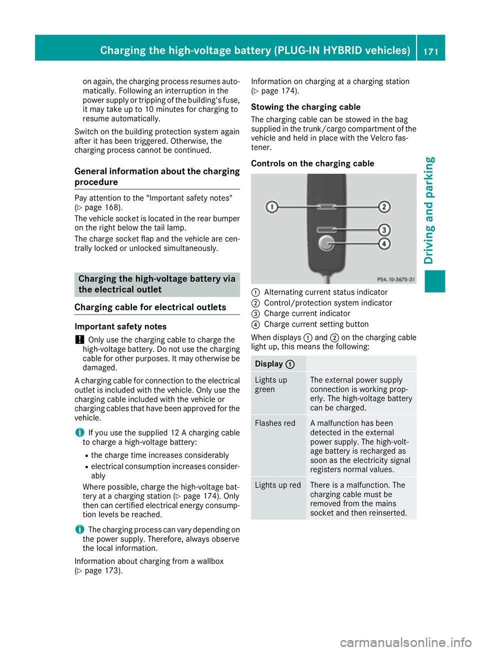
Controls on the charging cable
�C
Alternating current status indicator �D
Control/protection system indicator �
Page 192 of 398
R
the electrical system in the engine com-
partment, the battery or the fuses have
been tampered with. R
the battery is disconnected. R
the accelerator pedal has been depressed,
e.g. by a vehicle occupant.
There is a risk of an accident.
If you wish to exit the vehicle, always turn off
DISTRONIC PLUS and secure the vehicle
against rolling away.
For further information on deactivating
DISTRONIC PLUS ( Y
page 191).
If DISTRONIC PLUS detects that the vehicle in
front is stopping, it brakes your vehicle until it is
stationary.
Once your vehicle is stationary, it remains sta-
tionary and you do not need to depress the
brake.
i After a time, the electric parking brake
secures the vehicle and relieves the service
brake.
i Depending on the specified minimum dis-
tance, your vehicle will come to a standstill at
a sufficient distance behind the vehicle in
front. The specified minimum distance is set
using the control on the cruise control lever.
When DISTRONIC PLUS is activated, the trans-
mission is shifted automatically to position P if:R
the driver's seat belt is not fastened and the
driver's door is open. R
the engine is switched off, unless it is auto-
matical ly switched off by the ECO start/stop
functi on.
The electric parking brake secures the vehicle
automatically if DISTRONIC PLUS is activated
when the vehicle is stationary and: R
a system malfunction occurs. R
the power supply is not sufficient.
If a malfunction occurs, the transmission may
also shift into position P automatically.
Setting a speed X
Press the cruise control lever up �C for a
higher speed or down �D for a lower speed.X
To adjust the set speed in 1 mph incre-
ments (1 km/h increments): briefly press the cruise control lever up �C or down �D to
the pressure point.
Every time the cruise control lever is pressed
up �C or down �D the last speed stored is
increased or reduced. X
To adjust the set speed in 5 mph incre-
ments (1 0 km/h increments): briefly press
the cruise control lever up �C or down �D to
the pressure point.
Every time the cruise control lever is pressed
up �C or down �D , the last speed stored is
increased or reduced.
i If you accelerate to overtake, DISTRONIC
PLUS adjusts the vehicle's speed to the last
speed stored after you have finished overtak-
ing.
Setting a specified minimum distance You can set the specified minimum distance for
DISTRONIC PLUS by varying the time span
between one and two seconds. With this func-
tion, you can set the minimum distance that
DISTRONIC PLUS keeps to the vehicle in front,
dependent on vehicle speed. You can see this
distance in the multifunction display
( Y
page 191).
i Make sure that you maintain the minimum
distance to the vehicle in front as required by
law. Adjust the distance to the vehicle in front
if necessary.
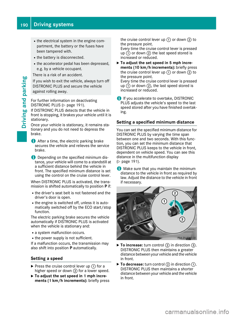
X
To increase: turn control �D in direction �
Page 196 of 398
the multifunction display. Steering Assist and
Stop&Go Pilot are activated.
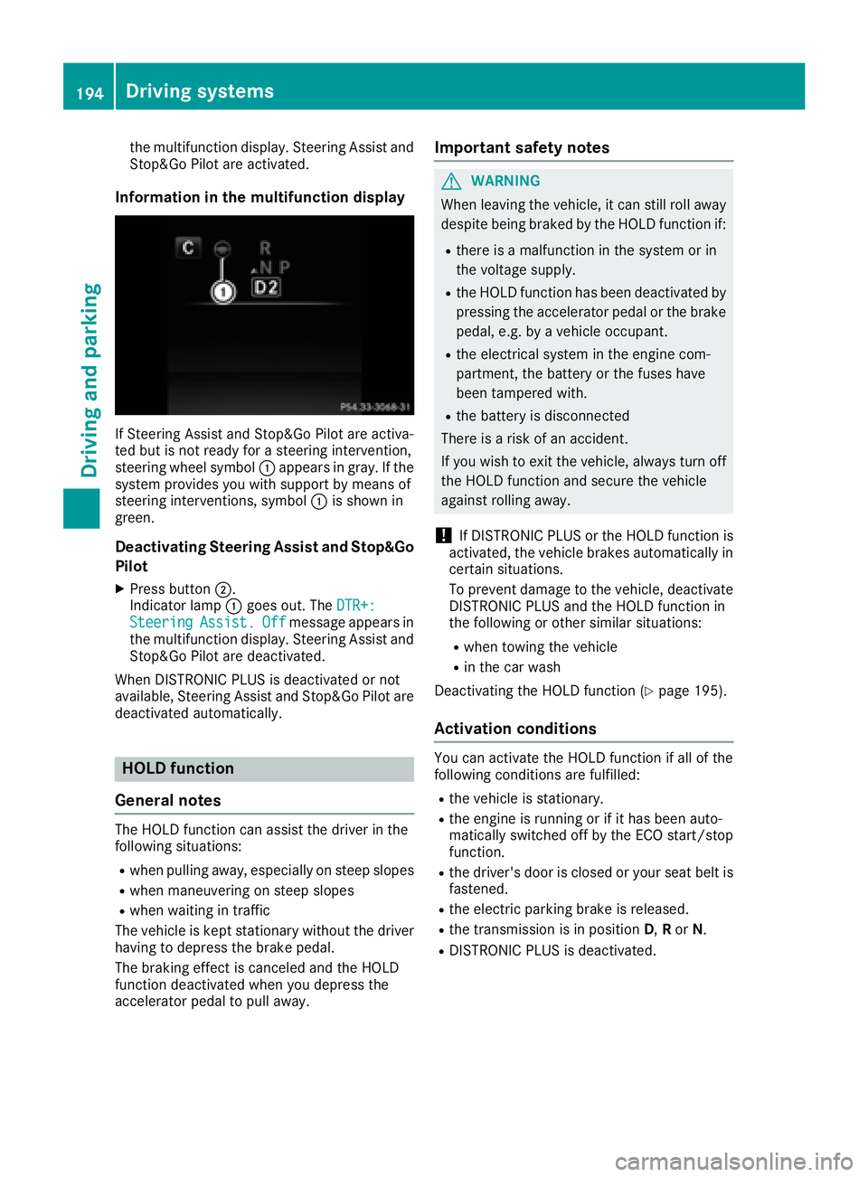
Information in the multifunction display
If Steering Assist and Stop&Go Pilot are activa-
ted but is not ready for a steering intervention,
steering wheel symbol �C appears in gray. If the
system provides you with support by means of
steering interventions, symbol �C is shown in
green.
Deactivating Steering Assist and Stop&Go
Pilot X
Press button �D .
Indicator lamp �C goes out. The DTR+:
Steering Assist. Off message appears in
the multifunction display. Steering Assist and
Stop&Go Pilot are deactivated.
When DISTRONIC PLUS is deactivated or not
available, Steering Assist and Stop&Go Pilot are
deactivated automatically.
HOLD function
General notes The HOLD function can assist the driver in the
following situations: R
when pulling away, especially on steep slopes R
when maneuvering on steep slopes R
when waiting in traffic
The vehicle is kept stationary without the driver
having to depress the brake pedal.
The braking effect is canceled and the HOLD
function deactivated when you depress the
accelerator pedal to pull away. Important safety notes
G WARNING
When leaving the vehicle, it can still roll away
despite being braked by the HOLD function if: R
there is a malfunction in the system or in
the voltage supply. R
the HOLD function has been deactivated by
pressing the accelerator pedal or the brake
pedal, e.g. by a vehicle occupant. R
the electrical system in the engine com-
partment, the battery or the fuses have
been tampered with. R
the battery is disconnected
There is a risk of an accident.
If you wish to exit the vehicle, always turn off
the HOLD function and secure the vehicle
against rolling away.
! If DISTRONIC PLUS or the HOLD function is
activated, the vehicle brakes automatically in
certain situations.
To prevent damage to the vehicle, deactivate
DISTRONIC PLUS and the HOLD function in
the following or other similar situations: R
when towing the vehicle R
in the car wash
Deactivating the HOLD function ( Y
page 195).
Activation conditions You can activate the HOLD function if all of the
following conditions are fulfilled: R
the vehicle is stationary. R
the engine is running or if it has been auto-
matically switched off by the ECO start/stop
function. R
the driver's door is closed or your seat belt is
fastened. R
the electric parking brake is released. R
the transmission is in position D , R or N .R
DISTRONIC PLUS is deactivated.194
Driving system s
Dr ivi ng an d parking
Page 206 of 398
R
that are parallel to the direction of travel and
at least 39.5 in (1.0 m) longer than your vehi-
cle R
that are at right angles to the direction of
travel and at least 39.5 in (1.0 m) wider than
your vehicle
i Note that Active Parking Assist cannot
measure the size of a parking space if it is at
right angles to the direction of travel. You will
need to judge whether your vehicle will fit into
the parking space.
When driving at speeds below 19 mph
(30 km/h), you will see the parking symbol as a
status indicator in the instrument cluster. When
a parking space has been detected, an arrow
towards the right or the left also appears. By
default, Active Parking Assist only displays park-
ing spaces on the front-passenger side. Parking
spaces on the driver's side are displayed as
soon as the turn signal on the driver's side is
activated. When parking on the driver's side,
this must remain switched on until you acknowl-
edge the use of Active Parking Assist by press-
ing the �v button on the multifunction steer-
ing wheel. The system automatically determines
whether the parking space is parallel or at right
angles to the direction of travel.
A parking space is displayed while you are driv-
ing past it, and until you are approximately 50 ft
(15 m) away from it.
Parking
G WARNING
If you leave the vehicle when it is only being
braked by Active Parking Assist it could roll
away if: R
there is a malfunction in the system or in
the voltage supply. R
the electrical system in the engine com-
partment, the battery or the fuses have
been tampered with. R
the battery is disconnected. R
the accelerator pedal has been depressed,
e.g. by a vehicle occupant.
There is a risk of an accident.
Before leaving the vehicle, always secure it
against rolling away. i When PARKTRONIC detects obstacles,
Active Parking Assist brakes automatically
during the parking process. You are respon-
sible for braking in good time. X
Stop the vehicle when the parking space sym-
bol shows the desired parking space in the
instrument cluster. X
Shift the transmission to position R .
The Start Park Assist?Yes: OKNo: �8
message appears in the multifunction display. X
To cancel the procedure: press the �8
button on the multifunction steering wheel or
pull away.
or X
To park using Active Parking Assist: press
the �v button on the multifunction steering
wheel.
The Park Assist Active Accelerate
and Brake Observe Surroundings mes-
sage appears in the multifunction display. X
Let go of the multifunction steering wheel. X
Back up the vehicle, being ready to brake at all
times. When backing up, drive at a speed
below approximately 6 mph (10 km/h). Oth-
erwise Active Parking Assist will be canceled.
Active Parking Assist brakes the vehicle to a
standstill when the vehicle approaches the
rear border of the parking space.
Maneuvering may be required in tight parking
spaces.
The Park Assist Active Select D Observe
Surroundings message appears in the multi-
function display. X
Shift the transmission to position D while the
vehicle is stationary.
Active Parking Assist immediately steers in
the other direction.
The Park Assist Active Accelerate
and Brake Observe Surroundings mes-
sage appears in the multifunction display.
i You will achieve the best results by waiting
for the steering procedure to complete before
pulling away. X
Drive forwards and be ready to brake at all
times.
Active Parking Assist brakes the vehicle to a
standstill when the vehicle approaches the
front border of the parking space.
Maneuvering may be required in tight parking
spaces.204
Driving systems
Driving and parking
Page 305 of 398
Settings in the climate menu Adjusting the climate mode settings By setting the climate mode you determine the
type of airflow. The setting is active when the air-
conditioning system is set to �X
( Y
page 133). X
Call up the climate control menu
( Y
page 302). X
To select Climate Mode : turn and press the
controller. X
To change the setting: turn the controller.
Exiting a menu: X
Press the �8 button.
The current airflow setting is shown in the cli-
mate control bar: DIFFUSE , MEDIUM or FOCUS .
Starting/stopping the perfume atomizer The perfume atomizer makes it possible to scent
the air in individual compartments in the vehicle
interior. Further information ( Y
page 138).X
Call up the climate control menu
( Y
page 302). X
To select Air Freshener : turn and press the
controller.
The setting element is active. X
To start/stop the perfume atomizer: press
the controller. X
To set the intensity: turn the controller when
the atomizer is switched on.
Exiting a menu: X
Press the �8 button.
Switching the ionization on/off
The ionization has a cleansing effect on the air in
the vehicle interior. Further information
( Y
page 140). X
Call up the climate control menu
( Y
page 302). X
To select Ionization : turn and press the
controller.
The setting element is active. X
To switch the ionization on/off: press the
controller.
Exiting a menu: X
Press the �8 button. Activating or deactivating pre-entry cli-
mate control via the SmartKey This function is available for PLUG ‑ IN HYBRID
vehicles.
PLUG-IN HYBRID: before getting in, the driver's
seat area can be briefly warmed or ventilated in
advance with the air from the air vents being pre-
cooled. X
Call up the climate control menu
( Y
page 302). X
To select Pre-entry Climate Control
via Key : turn and press the controller. X
To activate or deactivate: turn the control-
ler.
Exiting a menu: X
Press the �8 button.
Activating or deactivating pre-entry cli-
mate control at departure time This function is available for PLUG ‑ IN HYBRID
vehicles.
You can climatize the driver's seat and the vehi-
cle interior in time for the departure time set. X
Call up the climate control menu
( Y
page 302). X
To select Pre-entry Climate Ctrl. at
Departure Time : turn and press the control-
ler.
A rotary menu appears. X
To select the desired setting: turn the con-
troller.
The menu symbol, text and image show the
selected setting. X
To exit a menu:
Press the �8 button.
Settings in the bottom bar of the cli-
mate control menu
Switching cooling with air dehumidifica-
tion on/off X
Call up the climate control menu
( Y
page 302). X
Slide 6 the controller repeatedly until the
bottom bar is activated. X
To select �s A/C : turn and press the control-
ler. X
Switch cooling with air dehumidification on
�s or off �S .Operating system 303
Multimedia system Z
Page 359 of 398
Vehicles with 4MATIC may either be towed away
with both axles on the ground or be loaded up
and transported.
If the vehicle's transmission, front, or rear axle is
damaged, have the vehicle transported on a
truck or trailer.
In the event of damage to the electrical sys-
tem: if the battery is defective, the automatic
transmission will be locked in position P . To shift
the automatic transmission to position N , you
must provide power to the vehicle's electrical
system in the same way as when jump-starting
( Y
page 352).
Have the vehicle transported on a transporter or
trailer.
Tow-starting (emergency engine
starting)
! Vehicles with automatic transmission must
not be tow-started. You could otherwise dam-
age the automatic transmission.
i You can find information on "Jump-starting"
under ( Y
page 352).
Fuses
Important safety notes
G WARNING
If you manipulate or bridge a faulty fuse or if
you replace it with a fuse with a higher amper-
age, the electric cables could be overloaded.
This could result in a fire. There is a risk of an
accident and injury.
Always replace faulty fuses with the specified
new fuses having the correct amperage.
Blown fuses must be replaced with fuses of the
same rating, which you can recognize by the
color and value. The fuse ratings are listed in the
fuse allocation chart.
The fuse allocation chart is on the fuse box in the
trunk ( Y
page 357).
If a newly inserted fuse also blows, have the
cause traced and rectified at a qualified special-
ist workshop, e.g. an authorized Mercedes-Benz
Center. ! Only use fuses that have been approved for
Mercedes-Benz vehicles and which have the
correct fuse rating for the system concerned.
Otherwise, components or systems could be
damaged.
! Make sure that no moisture can enter the
fuse box when the cover is open.
! When closing the cover, make sure that it is
lying correctly on the fuse box. Moisture seep-
ing in or dirt could otherwise impair the oper-
ation of the fuses.
The fuses in your vehicle serve to close down
faulty circuits. If a fuse blows, all the compo-
nents on the circuit and their functions stop
operating.
Before changing a fuse Observe the important safety notes
( Y
page 357) X
Secure the vehicle against rolling away
( Y
page 177). X
Switch off the engine. X
Switch off all electrical consumers. X
Remove the SmartKey from the ignition lock.
or, in vehicles with KEYLESS-GO start-function
or KEYLESS ‑ GO X
Open the driver's door.
The on-board electronics now have status 0 .
This is the same as the SmartKey having been
removed.
The driver’s door can be closed again.
All indicator lamps in the instrument cluster
must be off.
The fuses are located in various fuse boxes: R
Fuse box on the driver's side of the dashboard R
Fuse box in the front-passenger footwell R
Fuse box in the engine compartment on the
driver's side R
Fuse box under the trunk floor on the right-
hand side of the vehicle, when viewed in the
direction of travel
Dashboard fuse box
! Do not use a pointed object such as a screw-
driver to open the cover in the dashboard. You
could damage the dashboard or the cover. Fuses 357
Breakdown assistance Z
Page 361 of 398
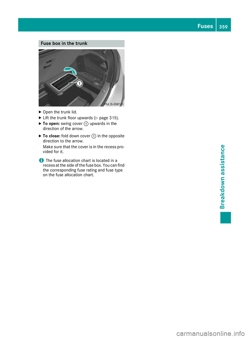
Fuse box in the trunk X
Open th e trunk lid.X
Lif t th e trunk floor upward s ( Y
page 315).X
To open : swin g cover �C upward s in th e
direction of th e arrow.X
To close: fol d down cover �C in th e opposit e
direction to th e arrow.
Mak e sure that th e cover is in th e recess pro -
vide d for it .
i The fus e allocation chart is locate d in a
recess at th e side of th e fus e box . You can fin d
th e corresponding fus e rating and fus e typ e
on th e fus e allocation chart . Fuses 359
Breakdown assistance Z