mirror MERCEDES-BENZ C-CLASS CABRIOLET 2018 Owner's Guide
[x] Cancel search | Manufacturer: MERCEDES-BENZ, Model Year: 2018, Model line: C-CLASS CABRIOLET, Model: MERCEDES-BENZ C-CLASS CABRIOLET 2018Pages: 350, PDF Size: 5.73 MB
Page 185 of 350

sors. A warning lamp lights up in the exterior
mirrors and draws your attention to vehicles
detected in the monitored area. If you then
switch on the corresponding turn signal to
change lane, you will also receive an optical and
audible warning.
Blind Spot Assist supports you from a speed of
approximately 20 mph (30 km/h).
Important safety notes
GWARNING
Blind Spot Assist does not react to:
Rvehicles overtaken too closely on the side,
placing them in the blind spot area
Rvehicles which approach with a large speed
differential and overtake your vehicle
As a result, Blind Spot Assist may not give
warnings in such situations. There is a risk of
an accident.
Always observe the traffic conditions care-
fully, and maintain a safe lateral distance.
Blind Spot Assist is only an aid. It may fail to
detect some vehicles and is no substitute for
attentive driving. Always ensure that there is
sufficient distance to the side for other road
users and obstacles.
iUSA only:
This device has been approved by the FCC as
a "Vehicular Radar System". The radar sensor
is intended for use in an automotive radar
system only. Removing, tampering with, or
altering the device will void any warranties,
and is not permitted by the FCC. Do not tam-
per with, alter, or use in any non-approved
way.
Any unauthorized modification to this device
could void the user’s authority to operate the
equipment.
Radar sensors
The radar sensors for Blind Spot Assist are inte-
grated into the rear bumper. Make sure that the bumpers are free from dirt, ice or slush. The
sensors must not be covered, for example by
cycle racks or overhanging loads. Following a
severe impact or in the event of damage to the
bumpers, have the function of the radar sensors
checked at a qualified specialist workshop.
Blind Spot Assist may no longer work properly.
Monitoring area
In particular, the detection of obstacles can be
impaired if:
Rthere is dirt on the sensors or anything else
covering the sensors
Rthere is poor visibility, e.g. due to fog, heavy
rain, snow or spray
Rthere are narrow vehicles, e.g. motorcycles or
bicycles
Rthe road has very wide lanes
Rthe road has narrow lanes
Ryou are not driving in the middle of the lane
Rthere are barriers or other road boundaries
Vehicles in the monitoring range are then not
indicated.
At a distance of around 1.6 ft (0.5 m) ;from the
vehicle, Blind Spot Assist monitors the area up
to 10 ft (3 m) next to =and behind :your
vehicle, as shown in the picture.
If the lanes are narrow, vehicles driving in the
lane beyond the lane next to your vehicle may be
indicated, especially if the vehicles are not driv-
ing in the middle of their lane. This may be the
case if there are vehicles driving at the inner
edge of their lanes.
Due to the nature of the system:
Rwarnings may be issued in error when driving
close to crash barriers or similar solid lane
borders.
Rwarnings may be interrupted when driving
alongside long vehicles, e.g. trucks, for a pro-
longed time.
Driving systems183
Driving and parking
Z
Page 186 of 350

Warning lamp
:Warning lamp
Blind Spot Assist is not active at speeds below
approximately 20 mph (30 km/h). Vehicles in
the monitoring range are then not indicated.
If a vehicle is detected within the blind spot
monitoring range at speeds above 20 mph
(30 km/h), warning lamp :on the correspond-
ing side lights up red. This warning is always
emitted when a vehicle enters the blind spot
monitoring range from behind or from the side.
When you overtake a vehicle, the warning only
occurs if the difference in speed is less than
7 mph (12 km/h).
If you select the reverse gear, Blind Spot Assist is not operational.
The brightness of the warning lamps is auto-
matically adapted to the brightness of the sur-
roundings.
Collision warning
If a vehicle is detected in the monitoring range of
Blind Spot Assist and you switch on the corre-
sponding turn signal, a double warning tone
sounds. The red warning lamp flashes on the
relevant exterior mirror. If the turn signal
remains on, detected vehicles are indicated by
the flashing of the red warning lamp on the exte-
rior mirror. There are no further warning tones.
Switching on Blind Spot Assist
XMake sure that Blind Spot Assist is activated
in the on-board computer (Ypage 205).
XTurn the SmartKey to position 2in the igni-
tion lock.
The red warning lamps on the exterior mirrors
light up until the engine is started.
Display in the assistance graphic
When Blind Spot Assist is activated, gray radar
waves propagating backwards appear next to
the vehicle in the assistance display in the mul-
tifunction display (
Ypage 203). Above a speed
of 20 mph (30 km/h), the color of the radar
waves in the assistance graphic changes to
green :. Blind Spot Assist is then ready for use.
Lane Keeping Assist
General notes
Lane Keeping Assist monitors the area in front of
your vehicle by means of multifunction cam-
era:which is attached behind the top of the
windshield. Active Lane Keeping Assist detects
lane markings on the road and can warn you
before you leave your lane unintentionally.
This function is available in the range between
40 mph and 120 mph (60 km/h and 200 km/h).
A warning may be given if a front wheel passes
over a lane marking. It will warn you by means of
intermittent vibration in the steering wheel for
up to 1.5 seconds.
184Driving systems
Driving and parking
Page 188 of 350

Ryou switch on thetur nsignals. In this event ,
th ewarnings are suppressed for acertain
period of time.
Ra drivin gsafet ysystem intervenes, e.g. ABS,
BA Sor ES P®.
Adaptive
Whe nAdaptive
is selected, no warnin gvibra-
tion occur sif:
Ryou switch on th etur nsignals. In this event ,
th ewarnings are suppressed for acertain
period of time.
Ra drivin gsafet ysystem intervenes, e.g. ABS,
BA Sor ES P®.
Ryou accelerate hard, e.g. kickdown .
Ryou brakehard.
Ryou steer actively, e.g. swerve to avoid an
obstacle or chang elanes quickly.
Ryou cut th ecorner on ashar pbend.
In order that you are warned only when neces-
sar yand in goo dtime if you cross th elan emark-
ing, th esystem recognizes certain condition s
and warn syou accordingly.
The warnin gvibration occur searlier if:
Ryou approac hth eouter lan emarking on a
bend.
Rth eroa dhas ver ywide lanes, e.g. afreeway.
Rth esystem detects soli dlan emarkings.
The warnin gvibration occur slater if:
Rth eroa dhas narrow lanes
Ryou cut th ecorner on aben d
Driving Assistance Plus package
Gene ral notes
The Drivin gAssistance Plus packag econsist sof
Distanc ePilo tDISTRONI C (Ypage 153), Active
Blind Spot Assis t (Ypage 186) and Active Lan e
Keepin gAssis t (Ypage 189).
Active Blind Spot Assist
Generalnotes
Active Blind Spot Assis tuses arada rsensor
system, pointe dtoward th erear of th evehicle,
to monitor th earea to th eside sof th evehicl e
whic hth edriver is unable to see . Awarnin glamp
lights up in th eexterio rmirror sand draw syour
attention to vehicles detecte din th emonitore darea
.If you then switch on th ecorrespondin g
tur nsignal to chang elane, you will also receiv e
an optica land audibl ewarning. If aris kof lateral
collision is detected, corrective brakin gmay
help you avoid acollision .Befor e acourse-cor-
recting brak eapplication ,Active Blind Spot
Assis tevaluates th espac ein th edirection of
travel and at th eside sof th evehicle. Fo rthis,
Active Blind Spot Assis tuses th eforward-facing
rada rsensors.
Active Blind Spot Assis tsupport syou from a
speed of approximately 20 mph (30 km/h).
Important safety notes
Active Blind Spot Assist isonly an aid and is not
a substitute for attentive driving.
GWARNING
Active Blind Spot Assist does not react to:
Rvehicles overtaken too closely on the side,
placing them in the blind spot area
Rvehicles which approach with a large speed
differential and overtake your vehicle
As a result, Active Blind Spot Assist may ne i-
ther give warnings nor intervene insuch sit-
uations. There isa risk of an accident.
Always observe the traffic conditions care-
fully, and maintain a safe lateral distance.
iUSA only: This device has been approved by
the FCC as a "Vehicular Radar System". The
radar sensor is intended for use inan auto-
motive radar system only. Removal, tamper-
ing, or altering of the device willvoid any war-
ranties, and isnot permitted by the FCC. Do
not tamper with, alter, or use inany non-
approved way.
Any unauthorized modification to this device
could void the user's authority to operate the
equipment.
iCanada only: This device complies with
RSS -210 of Industry Canada. Operation is
subject to the following two conditions:
1. This device may not cause interference,
and
2. This device must accept any interference
received, including interference that may
cause undesired operation of the device.
Removal, tampering, or altering of the device
will void an
y warranties, and is not permitte
d.
186Driving systems
Driving and parking
Page 190 of 350

If you select the reverse gear, Active Blind Spot
Assist is not operational.
The brightness of the warning lamps is auto-
matically adapted to the brightness of the sur-
roundings.
When Active Blind Spot Assist is activated, gray
radar waves propagating backward appear next
to the vehicle in the assistance display in the
multifunction display. Above a speed of 20 mph
(30 km/h), the color of the radar waves in the
assistance display changes to green;. Active
Blind Spot Assist is then ready for use.
Visual and acoustic collision warning
If you switch on the turn signals to change lanes
and a vehicle is detected in the side monitoring
range, you receive a visual and acoustic collision
warning. You will then hear a double warning
tone and red warning lamp :flashes. If the turn
signal remains on, detected vehicles are indica-
ted by the flashing of red warning lamp :.
There are no further warning tones.
Course-correcting brake application
If Active Blind Spot Assist detects a risk of a lat-
eral collision in the monitoring range, a course-
correcting brake application is carried out. This
is meant to assist you in avoiding a collision.
GWARNING
A course-correcting brake application cannot always prevent a collision. There is a risk of an
accident.
Always steer, brake or accelerate yourself,
especially if Active Blind Spot Assist warns
you or makes a course-correcting brake appli-
cation. Always maintain a safe distance at the
sides. If a course-correcting brake application occurs,
red warning lamp
:flashes in the exterior mir-
ror and a double warning tone sounds. In addi-
tion, a display underlining the danger of a side
collision appears in the multifunction display.
In very rare cases, the system may make an
inappropriate brake application. A course-cor-
recting brake application may be interrupted at
any time by countersteering slightly or acceler-
ating.
The course-correcting brake application is avail-
able in the speed range between 20 mph
(30 km/h) and 120 mph (200 km/h).
Either no braking application, or a course-cor-
recting brake application adapted to the driving situation occurs if:
Rthere are vehicles or obstacles, e.g. crash
barriers, located on both sides of your vehicle.
Ra vehicle approaches you too closely at the
side.
Ryou have adopted a sporty driving style with
high cornering speeds.
Ryou clearly brake or accelerate.
Ra driving safety system intervenes, e.g. ESP®
or PRE-SAFE®Brake.
RESP®is switched off.
Ra loss of tire pressure or a defective tire is
detected.
Switching on Active Blind Spot Assist
XMake sure that Active Blind Spot Assist is
activated in the on-board computer
(
Ypage 205).
XSwitch on the ignition.
Warning lamps :in the exterior mirrors light
up red for approximately 1.5 seconds.
Gray radar waves propagating backwards
appear next to the vehicle in the assistance
graphic in the multifunction display ;.
Above a speed of 20 mph (30 km/h), the color
of the radar waves in the assistance display
changes to green ;. Active Blind Spot Assist
is then ready for use.
188Driving systems
Driving and parking
Page 270 of 350
pants may come into contact with the liquid
and if it is hot, they may be scalded. You maybe distracted from the traffic conditions and
you could lose control of the vehicle. There is
a risk of an accident and injury.
Only use the cup holder when the vehicle is
stationary. Only use the cup holder for con-
tainers of the right size. Always close the con-tainer, particularly if the liquid is hot.
GWARNING
If objects in the passenger compartment are
stowed incorrectly, they can slide or be
thrown around and hit vehicle occupants. In
addition, cupholders, open stowage spaces
and mobile phone brackets cannot always
retain all objects they contain. There is a risk of injury, particularly in the event of sudden
braking or a sudden change in direction.
RAlways stow objects so that they cannot be
thrown around in such situations.
RAlways make sure that objects do not pro-
trude from stowage spaces, parcel nets or
stowage nets.
RClose the lockable stowage spaces before
starting a journey.
RAlways stow and secure heavy, hard, poin-
ted, sharp-edged, fragile or bulky objects in
the trunk.
!Only use the cup holders for containers of
the right size and which have lids. The drinks
could otherwise spill.
!Do not expose drinks bottles in the cup
holder in the center console to continuous,
strong and direct sunlight. The passenger
compartment in the area of the center con-
sole can otherwise be damaged by the con-
centrated and reflected sunlight.
Observe the loading guidelines (
Ypage 263).
Cup holder in the front center console
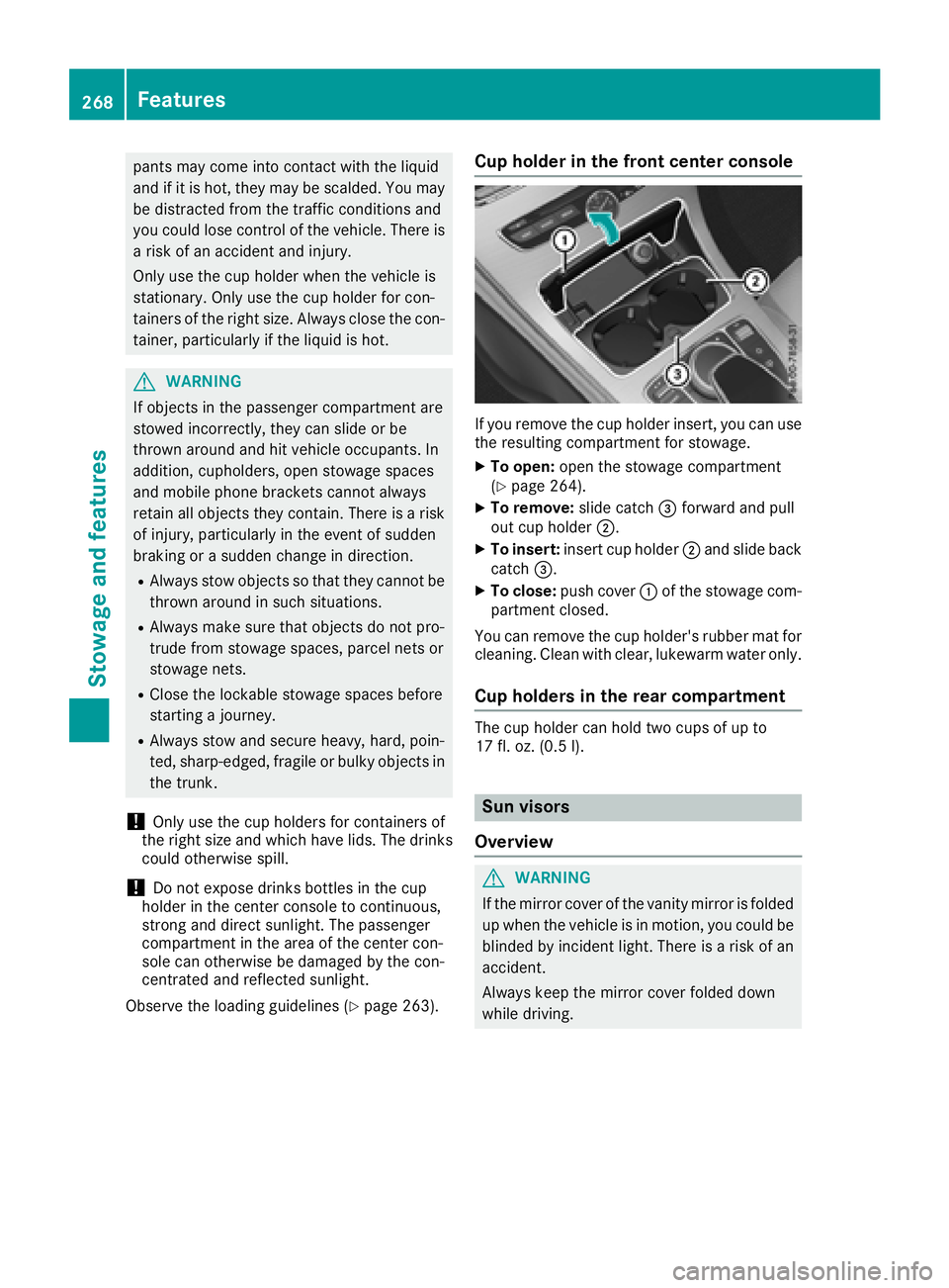
If you remove the cup holder insert, you can use
the resulting compartment for stowage.
XTo open: open the stowage compartment
(Ypage 264).
XTo remove: slide catch=forward and pull
out cup holder ;.
XTo insert:insert cup holder ;and slide back
catch =.
XTo close: push cover :of the stowage com-
partment closed.
You can remove the cup holder's rubber mat for
cleaning. Clean with clear, lukewarm water only.
Cup holders in the rear compartment
The cup holder can hold two cups of up to
17 fl. oz. (0.5 l).
Sun visors
Overview
GWARNING
If the mirror cover of the vanity mirror is folded
up when the vehicle is in motion, you could be
blinded by incident light. There is a risk of an
accident.
Always keep the mirror cover folded down
while driving.
268Features
Stowage and features
Page 271 of 350
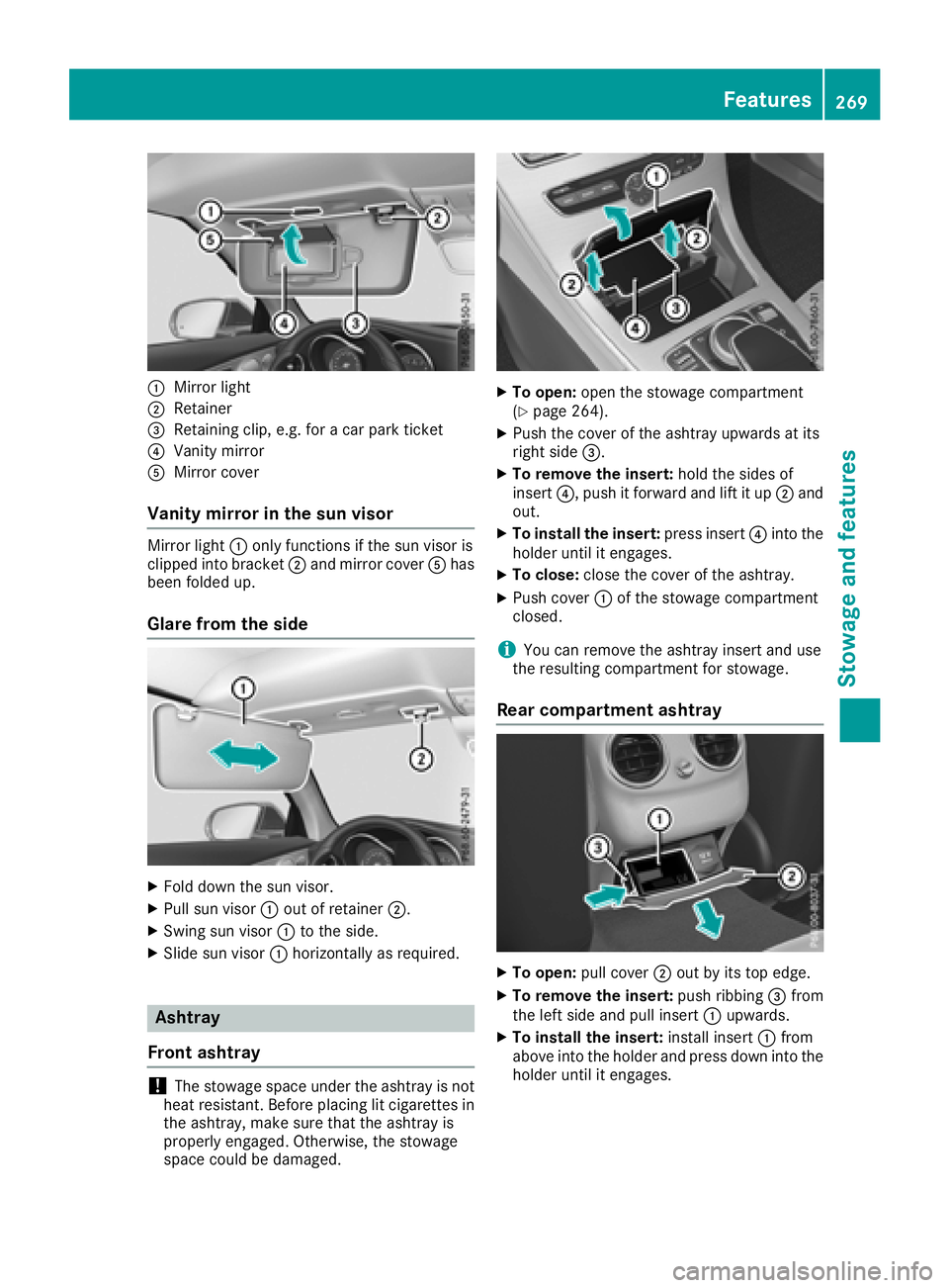
:Mirror light
;Retainer
=Retaining clip, e.g. for a car park ticket
?Vanity mirror
AMirror cover
Vanity mirror in the sun visor
Mirror light:only functions if the sun visor is
clipped into bracket ;and mirror cover Ahas
been folded up.
Glare from the side
XFold down the sun visor.
XPull sun visor :out of retainer ;.
XSwing sun visor :to the side.
XSlide sun visor :horizontally as required.
Ashtray
Front ashtray
!The stowage space under the ashtray is not
heat resistant. Before placing lit cigarettes in the ashtray, make sure that the ashtray is
properly engaged. Otherwise, the stowage
space could be damaged.
XTo open: open the stowage compartment
(Ypage 264).
XPush the cover of the ashtray upwards at its
right side =.
XTo remove the insert: hold the sides of
insert ?, push it forward and lift it up ;and
out.
XTo install the insert: press insert?into the
holder until it engages.
XTo close: close the cover of the ashtray.
XPush cover :of the stowage compartment
closed.
iYou can remove the ashtray insert and use
the resulting compartment for stowage.
Rear compartment ashtray
XTo open: pull cover ;out by its top edge.
XTo remove the insert: push ribbing=from
the left side and pull insert :upwards.
XTo install the insert: install insert:from
above into the holder and press down into the
holder until it engages.
Features269
Stowage and features
Z
Page 279 of 350

Another function of the Vehicle Health Check is
the transfer of service data to the Customer
Assistance Center. If a service is due, the display
shows a message to this effect together with
information about any special offers at your
workshop.
This information can also be called up under
"Owners Online" at http://www.mbusa.com.
Information on the data stored in the vehicle
(
Ypage 32).
Information on Roadside Assistance
(
Ypage 29).
Downloading routes
Downloading routes allows you to transfer and
save predefined routes in the navigation sys-
tem.
A route can be prepared and sent by either a
customer service representative or under "Own-
ers Online" at http://www.mbusa.com.
Each route can include up to four way points.
Once a route has been received by the naviga-
tion system, you will see the Do
youwanttostart route guidance? DestinationReceived destination has been savedin "Previous destinations".message on
the multimedia system display.
The route is saved.
XTo start route guidance: selectYes.
An overview of the route is shown in the dis-
play.
If you select No
, the saved route can be called
up later in the navigation menu.
XSelect Start.
Route guidance starts.
Downloaded and saved routes can be called up
again.
Speed alert
You can define the upper speed limit, which
must not be exceeded by the vehicle.
If this selected speed is exceeded by the vehicle,
a message will be sent to the Customer Assis-
tance Center. The Customer Assistance Center
then forwards this information to you.
You can select the way in which you receive this
information beforehand. Possible options
include text message, e-mail or an automated
call. The data you receive contains the following
information:
Rthe location where the speed limit was excee-
ded
Rthe time at which the speed limit was excee-
ded
Rthe selected speed limit which was exceeded
Geo fencing
Geo fencing allows you to select areas which the
vehicle should not enter or leave. You will be
informed if the vehicle crosses the boundaries
of the selected areas. You can select the way in
which you receive this information beforehand.
Possible options include text message, e-mail or
an automated call.
The area can be determined as either a circle or
a polygon with a maximum of ten corners. You
can specify up to ten areas simultaneously. Dif-
ferent settings are possible for each area.
These settings can be called up under "Owners
Online" at http://www.mbusa.com.
Alternatively, you can trigger an Info call and
notify the customer service representative that
you wish to activate geo-fencing.
Currently inactive areas can be activated by text
message.
Triggering the vehicle alarm
With this function, you can trigger the vehicle's
panic alarm via text message. An alarm sounds
and the exterior lighting flashes. Depending on
the setting, the panic alarm lasts five or ten sec- onds. Afterwards, the alarm switches off.
Garage door opener
General notes
The HomeLink®garage door opener integrated
in the rear-view mirror allows you to operate up
to three different door and gate systems.
Use the integrated garage door opener only on
garage doors that:
Rhave safety stop and reverse features and
Rmeet current U.S. federal safety standards
Once programed, the integrated garage door
opener in the rear-view mirror will assume the
function of the garage door system's remote
Features277
Stowag ean d features
Z
Page 280 of 350

control. Please also read the operating instruc-
tions for the garage door system.
When programming a garage door opener, park
the vehicle outside the garage. Do not run the
engine while programming.
Certain garage door drives are incompatible
with the integrated garage door opener. If you
have difficulty programing the integrated garage
door opener, contact an authorized Mercedes-
Benz Center.
Alternatively, you can call the following tele-
phone assistance services:
RUSA:Mercedes-Benz Customer Assistance
Center at 1-800-FOR-MERCedes
RCanada: Customer Service at
1-800-387-0100
RHomeLink®hotline 1-800-355-3515 (free of
charge)
More information on HomeLink
®and/or com-
patible products is also available online at
http://www.homelink.com.
Notes on the declaration of conformity
(
Ypage 263).
USA: FCC ID: CB2HMIHL4
Canada: IC: 279B-HMIHL4
Important safety notes
GWARNING
When you operate or program the garage door
with the integrated garage door opener, per-
sons in the range of movement of the garage
door can become trapped or struck by the
garage door. There is a risk of injury.
When using the integrated garage door
opener, always make sure that nobody is
within the range of movement of the garage
door.
GWARNING
Combustion engines emit poisonous exhaust
gases such as carbon monoxide. Inhaling
these exhaust gases leads to poisoning. There
is a risk of fatal injury. Therefore never leave
the engine running in enclosed spaces with-
out sufficient ventilation.
Programming
Programming buttons
Pay attention to the "Important safety notes"
(Ypage 278).
Garage door remote control Ais not included
with the integrated garage door opener.
XTurn the SmartKey to position 2in the igni-
tion lock (Ypage 123).
XSelect one of buttons ;to? to use to con-
trol the garage door drive.
XTo start programming mode: press and
hold one of buttons ;to? on the integrated
garage door opener.
The garage door opener is in programming
mode. After a short time, indicator lamp :
lights up yellow.
Indicator lamp :lights up yellow as soon as
button ;,=or? is stored for the first time.
If the selected button has already been pro-
grammed, indicator lamp :will only light up
yellow after ten seconds have elapsed.
XRelease button ;,=or?. Indicator
lamp :flashes yellow.
XTo program the remote control: point
garage door remote control Atowards but-
tons ;to? on the rear-view mirror at a dis-
tance of 2 to 8 in (5 to 20 cm).
XPress and hold button Bon remote control
A until indicator lamp :lights up green.
When indicator lamp :lights up green: pro-
gramming is finished.
When indicator lamp :flashes green: pro-
gramming was successful. The rolling code
must be synchronized (
Ypage 279).
XRelease button Bon remote control Afor
the garage door drive system.
If indicator lamp :lights up re
d: repeat the
programing procedure for the corresponding
button on the rear-view mirror. When doing
278Features
Stowage and features
Page 281 of 350
so, vary the distance between remote control
Aand the rear-view mirror.
The required distance between remote con-
trol Aand the integrated garage door opener
depends on the garage door drive system.
Several attempts might be necessary. You
should test every position for at least
25 seconds before trying another position.
Synchronizing the rolling code
Pay attention to the "Important safety notes"
(Ypage 278).
If the garage door system uses a rolling code,
you will also have to synchronize the garage
door system with the integrated garage door
opener in the rear-view mirror. To do this you will
need to use the programming button on the door
drive control panel. The programming button
may be located in different places depending on
the manufacturer. It is usually located on the
door drive unit on the garage ceiling.
Familiarize yourself with the garage door drive
operating instructions, for example under "Pro-
gramming additional remote controls", before
carrying out the following steps.
Your vehicle must be within reach of the garage
door or gate opener drive. Make sure that nei-
ther your vehicle nor any persons/objects are
present within the sweep of the door or gate.
XTurn the SmartKey to position 2in the igni-
tion lock (Ypage 123).
XGet out of the vehicle.
XPress the programming button on the door
drive unit.
Usually, you now have 30 seconds to initiate
the next step.
XGet into the vehicle.
XPress previously programmed button ;,=
or ? on the integrated garage door opener
repeatedly and in quick succession until the
door closes.
The rolling code synchronization is then com- plete.
Notes on programming the remote con-
trol
Canadian radio frequency laws require a "break"
(or interruption) of the transmission signals
after broadcasting for a few seconds. Therefore,
these signals may not last long enough for the
integrated garage door opener. The signal is not
recognized during programming. Comparable with Canadian law, some U.S. garage door open-
ers also feature a "break".
Proceed as follows:
Rif you live in Canada.
Rif you have difficulties programming the
garage door opener (regardless of where you
live) when using the programming steps.
XPress and hold one of buttons
;to? on the
integrated garage door opener. After a short time, indica
tor lamp:lights up
yellow.
XRelease the button.
Indicator lamp :flashes yellow.
XPress button Bof garage door remote con-
trol Afor two seconds, then release it for two
seconds.
XPress button Bof the remote control A
again and hold for two seconds.
XRepeat this sequence on button Bof remote
control Auntil indicator lamp :lights up
green.
When indicator lamp :lights up green: pro-
gramming is finished.
When indicator lamp :flashes green: pro-
gramming was successful. The next step is to
synchronize the rolling code.
XRelease button Bof remote control Aof the
garage door drive.
If indicator lamp :lights up red: repeat the
programming process for the corresponding
button on the rear-view mirror. When doing
so, vary the distance between remote control
A and the rear-view mirror.
The required distance between remote con-
trol Aand the integrated garage door opener
depends on the garage door drive system.
Several attempts might be necessary. You
should test every position for at least
25 seconds before trying another position.
Problems when programming
If you are experiencing problems programing
the integrated garage door opener on the rear-
view mirror, take note of the following instruc-
tions:
RCheck the transmitter frequency used by
garage door drive remote control Aand
whether it is supported. The transmitter fre-
quency can usually be found on the back of
remote control Afor the garage door drive.
Features279
Stowage and features
Z
Page 282 of 350
The garage door opener is compatible with
devices which operate in the frequency range
of 280 to 433 MHz.
RReplace the batteries in garage door remote
controlA. This increases the likelihood that
garage door remote control Awill transmit a
strong and precise signal to the integrated
garage door opener.
RWhen programming, hold remote control A
at varying distances and angles and from but-
tons ;to? which you are programming. Try
various angles at a distance between 2and
8 inches (5to 20 cm) or at the same angle but
at varying distances.
RIf another remote control Ais available for
the same garage door drive, repeat the same
programming steps with this remote control
A. Before performing these steps, make sure
that new batteries have been installed in
garage door drive remote control A.
RNote that some remote controls only transmit
for a limited amount of time (the indicator
lamp on the remote control goes out). Press
buttonBon remote control Aagain before
transmission ends.
RAlign the antenna cable of the garage door
opener unit. This can improve signal recep-
tion/transmission.
Opening/closing the garage door
After it has been programmed, the integrated
garage door opener performs the function of the
garage door system remote control. Please also
read the operating instructions for the garage
door system.
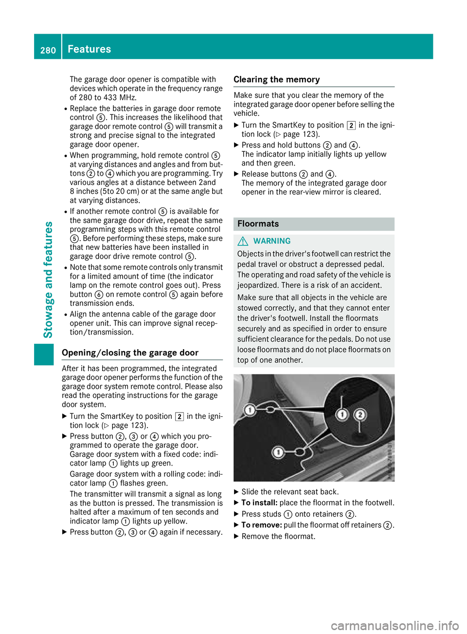
XTurn the SmartKey to position 2in the igni-
tion lock (Ypage 123).
XPress button ;,=or? which you pro-
grammed to operate the garage door.
Garage door system with a fixed code: indi-
cator lamp :lights up green.
Garage door system with a rolling code: indi-
cator lamp :flashes green.
The transmitter will transmit a signal as long
as the button is pressed. The transmission is
halted after a maximum of ten seconds and
indicator lamp :lights up yellow.
XPress button ;,=or? again if necessary.
Clearing the memory
Make sure that you clear the memory of the
integrated garage door opener before selling the
vehicle.
XTurn the SmartKey to position 2in the igni-
tion lock (Ypage 123).
XPress and hold buttons ;and ?.
The indicator lamp initially lights up yellow
and then green.
XRelease buttons ;and ?.
The memory of the integrated garage door
opener in the rear-view mirror is cleared.
Floormats
GWARNING
Objects in the driver's footwell can restrict the pedal travel or obstruct a depressed pedal.
The operating and road safety of the vehicle is
jeopardized. There is a risk of an accident.
Make sure that all objects in the vehicle are
stowed correctly, and that they cannot enter
the driver's footwell. Install the floormats
securely and as specified in order to ensure
sufficient clearance for the pedals. Do not use
loose floormats and do not place floormats on
top of one another.
XSlide the relevant seat back.
XTo install: place the floormat in the footwell.
XPress studs :onto retainers ;.
XTo remove:pull the floormat off retainers ;.
XRemove the floormat.
280Features
Stowage and features