tow MERCEDES-BENZ C-CLASS CABRIOLET 2021 Service Manual
[x] Cancel search | Manufacturer: MERCEDES-BENZ, Model Year: 2021, Model line: C-CLASS CABRIOLET, Model: MERCEDES-BENZ C-CLASS CABRIOLET 2021Pages: 545, PDF Size: 9.48 MB
Page 120 of 545

*
NO
TEDama getoobjects caused by
placing them in the mobile phone stow‐
age compartment If objects are placed in
the mobile phone
stow age compartment, they may be dam‐
aged byelectromagnetic fields. #
Do not place credit cards, data storage
devices, ski passes or other objects
sensitive toelectromagnetic fields in
th e mobile phone stowage compart‐
ment. *
NO
TEDama getothe mobile phone
stow age compartment caused byliquids If liquids enter
the mobile phone stowage
compartment, the compartment may be
damaged. #
Ensure that no liquids enter the mobile
phone stowage compartment. The
following no tes on wirelessly charging the
mobile phone must be obser ved:
R Depending on theve hicle equipment, the
mobile phone is connected totheve hicle's
ex terior aerial via thech arging module.
R The charging function and wireless connec‐
tion of the mobile phone totheve hicle's
ex terior aerial are only available if the ignition
is switched on.
R Small mobile phones may not be able tobe
ch arge d in everyposition of the mobile
phone stowage compartment.
R Largemobile phones which do not rest flat in
th e mobile phone stowage compartment may
not be able tobe charge d or connec ted with
th eve hicle's exterior aerial.
R The mobile phone may heat up during the
ch arging process. This may particular ly
depend on the applications (apps) cur rently
open in the bac kground.
R Toensure more ef ficient charging and con‐
nection with theve hicle's exterior aerial,
re mo vethe pr otective co ver from the mobile phone. Pr
otective co vers which are neces‐
sary for wireless charging are an exception. Wire
lessly charging a mobile phone Re
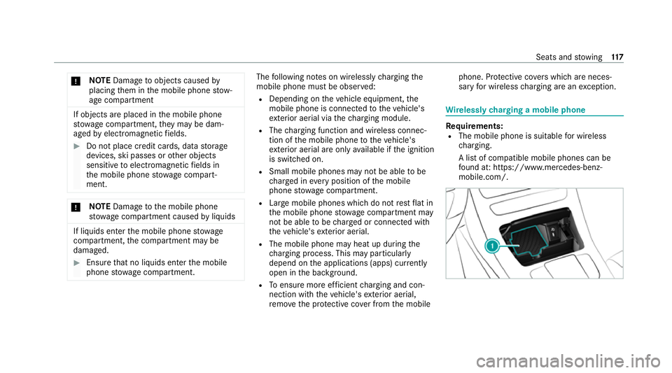
quirements:
R The mobile phone is suitable for wireless
ch arging.
A list of compatible mobile phones can be
fo und at: https://www.mercedes-benz-
mobile.com/. Seats and
stowing 117
Page 121 of 545

#
Place the mobile phone as close tothe
centre of mat 1as possible wi th the display
fa cing up wards.
When thech arging symbol is shown in the
multimedia sy stem, the mobile phone is
being charge d.
Malfunctions during thech arging process are
shown in the media displa y.
% The mat can be remo vedby theta bfor
cleaning, e.g. using clean, lu kewa rm wate r. Fi
tting/ removing the floormats &
WARNING Risk of accident due to
objects in the driver's foot we ll
Objects in the driver's foot we ll may impede
pedal tr avel or block a depressed pedal.
This jeopardises the operating and road
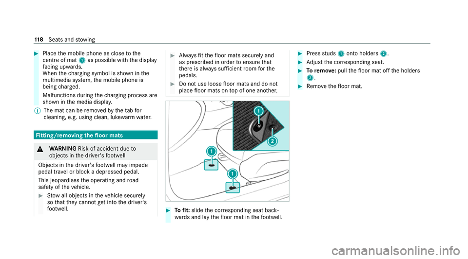
saf ety of theve hicle. #
Stow all objects in theve hicle securely
so that they cannot getinto the driver's
fo ot we ll. #
Alw aysfit th efloor mats securely and
as prescribed in order toensure that
th ere is alw ays suf ficient room forthe
pedals. #
Do not use loose floor mats and do not
place floor mats on top of one ano ther. #
Tofit: slide the cor responding seat back‐
wa rds and lay thefloor mat in thefo ot we ll. #
Press studs 1onto holders 2. #
Adjust the cor responding seat. #
Toremo ve: pull thefloor mat off the holders
2. #
Remo vethefloor mat. 11 8
Seats and stowing
Page 145 of 545

#
After no more than five seconds, take your
left foot quickly off the brake, but keep the
accelerator pedal depressed.
The vehicle pulls away at maximum accelera‐
tion. #
Swit chon ESP ®
once the acceleration proce‐
dure is comple te.
Ending optimised acceleration #
Remo veyour foot from the accelerator pedal. #
Reactivate the ESP ®
.
% Afteryo u pull away with optimised accelera‐
tion, components of the driv etra in can
become very hot, which means that opti‐
mised acceleration values may be reached
again on lyafte r a few minutes. Note
s on driving &
WARNING Risk of accident due to
objects in the driver's foot we ll
Objects in the driver's foot we ll may impede
pedal tr avel or block a depressed pedal. This jeopardises
the operating and road
saf ety of theve hicle. #
Stow all objects in theve hicle securely
so that they cannot getinto the driver's
fo ot we ll. #
Alw aysfit th efloor mats securely and
as prescribed in order toensure that
th ere is alw ays suf ficient room forthe
pedals. #
Do not use loose floor mats and do not
place floor mats on top of one ano ther. &
WARNING Risk of accident due toincor‐
re ct foot we ar
Incor rect foot we ar includes, forex ample:
R shoes with plat form soles
R shoes with high heels
R slippers
There is a risk of an accident. #
Alw ayswe ar suitable foot we ar so that
yo u can operate the pedals safel y. &
WARNING Risk of accident if the ignition
is switched off while driving
If yo u swit choff the ignition while driving,
saf ety functions are restricted or no longer
av ailable.
This may af fect the po werst eering sy stem
and the brake forc e boosting, forex ample.
Yo u will need touse considerably more force
to steer and brake, forex ample. #
Do not swit choff the ignition while driv‐
ing. &
DANG ER Risk of death caused by
ex haust gases
Combustion engines emit poisonous exhaust
ga ses such as carbon monoxide. Inhaling
th ese exhaust gases is hazardous tohealth
and leads topoisoning. #
Never lea vethe engine or, if present,
th e auxiliary heating running in an
enclosed space wi thout suf ficient venti‐
lation. 14 2
Driving and pa rking
Page 151 of 545

of
theve hicle will turn green. The remaining seg‐
ments will initially stay white. If youta ke your
fo ot off the accelerator pedal in good time, the
re maining segments on the display will succes‐
sively turn green until theeve nt shown is
re ached. The driv etra in will be set for maximum
fuel econom y.Re cuperation will charge the bat‐
te ry.Re cuperation will be adap tedto the selec‐
te d drive prog ram.
The event will be shown for a short time af ter it
has been passed. If there is no response tothe
Foot off the accelerator prompt,th e segments
will remain white.
If th eeve nt in volves a vehicle in front, all seg‐
ments will immediately turn green once there is
a re sponse totheFoot off the accelerator
prom pt.
Fo r active ECO Assist in drive program ;,
symbol 3will appear on the multifunction dis‐
play and on the head-up display beside transmis‐
sion position h. Symbol3will also appear
when the assis tant displ ayis not selec ted. If
th e sy stem does not inter vene du ring the
eve nt ahead, no thing will be displa yed. The sys‐
te m will be passive.
ECO Assist is active only in drive programs ;
and A.
Sy stem limits
ECO Assist can function even more precisely if
th ero ute is adhered towhen route guidance is
active. The basic function is also available with‐
out active route guidance. Notall information
and traf fic situations can be fore seen. The qual‐
ity depends on the map data.
ECO Assist is only an aid. The driver is responsi‐
ble forke eping a safe dis tance from theve hicle
in front, forve hicle speed and for braking in
good time. The driver must be ready tobrake at
all times ir respective of whe ther the sy stem
inter venes.
The sy stem may be impaired or may not function
in thefo llowing situations:
R If visibility is poor, e.g. due toinsuf ficient illu‐
mination of thero ad, high lyvariable shade
conditions, rain, sno w,fog or heavy spr ay.R
Ifth ere is glare, e.g. from oncoming traf fic,
di re ct sunlight or reflections.
R Ifth ere is dirt on the windscreen in the area
of the multifunction camera or the camera is
mis ted up, damaged or obscured.
R Ifro ad signs are hard todetect, e.g. due to
dirt, snow or insuf ficient lighting, or because
th ey are obscured.
R Ifth e information on the navigation sy stem's
digital map is incor rect or out of da te.
R If signs are ambiguous, e.g. road signs in
ro adwor ksor in adjacent lanes. DY
NA MIC SELECT switch Fu
nction of theDY NA MIC SELECT switch *
NO
TEMercedes-AMG vehicles #
Obser vethe no tes in the Supplement.
Yo u could otherwise failto recognise
dangers. %
Depending on the engine and equipment,
th eve hicle has dif fere nt drive programs. 14 8
Driving and pa rking
Page 154 of 545

&
WARNING Risk of accident and inju ry
due toleaving children unat tended in the
ve hicle
If ch ildren are left unat tended in theve hicle,
th ey could, in pa rticular:
R open doors, thereby endangering other
persons or road users.
R get out and be stru ck byoncoming traf‐
fi c.
R ope rate ve hicle equipment and become
trapped, forex ample.
In addition, thech ildren could also set the
ve hicle in motion by,fo rex ample:
R releasing the parking brake.
R changing the transmission position.
R starting theve hicle. #
Never lea vechildren unat tended in the
ve hicle. #
When leaving theve hicle, alw aysta ke
th eke y with you and lock theve hicle. #
Keep theve hicle key out of there ach of
ch ildren. Use
the DIRECT SELECT le verto switch the
transmission position. The cur rent transmission
position is displ ayed in the multifunction displa y. j
Park position
k Reversege ar i
Neut ral
h Drive position
En gaging reve rsege ar R #
Depress the brake pedal and push the
DIRECT SELECT le ver upwards past thefirst
point of resis tance.
En gaging neutral N #
Depress the brake pedal and push the
DIRECT SELECT le ver up or down tothefirst
point of resis tance.
% Toshift into neutral iwith the ignition on,
push the selector le ver up or down for sev‐
eral seconds tothefirs t point of resis tance.
Subsequently releasing the brake pedal will
allow youto mo vetheve hicle freel y,e.g. topush
it or tow it away.
Proceed as follo ws ifyo uwa ntthe automatic
transmission toremain in neutral i
i,even if
th e ignition is switched off or the driver's
door is opened: #
Dep ress the brake pedal and engage neutral
i when the car is stationar y. Driving and pa
rking 151
Page 166 of 545

#
Never lea vethe engine or, if present,
th e auxiliary heating running in an
enclosed space wi thout suf ficient venti‐
lation. &
WARNING Risk of inju rywhen opening
or closing a door with thega rage door
opener
When you operate or program the door with
th e integrated garage door opener, persons
in thera nge of mo vement of the door may
become trapped or be stru ck bythe door. #
Alw ays make sure that nobody is within
th era nge of mo vement of the door. Re
quirements:
R The vehicle has been par ked outside the
ga rage or outside thera nge of mo vement of
th e door.
R The engine is switched off.
R The ignition is switched on.
% The garage door opener function is alw ays
av ailable when the ignition is switched on. #
Press and hold button 1,2or3 that you
wish toprog ram.
Indicator lamp 4flashes yello w.
% It can take up to20 seconds before the indi‐
cator lamp flashes yello w. #
Release the pr eviously pressed button.
Indicator lamp 4continues toflash yello w. #
Point remo tecontrol 5from a di stance of
1 cm to8 cm towa rds button 1,2or3. #
Press and hold button 6ofremo tecontrol
5 until one of thefo llowing signals appears:
R Indicator lamp 4lights up green contin‐
uousl y.Programming is comple te.
R Indicator lamp 4flashes green. Pro‐
gramming was successful. Additionall y,
synchronisation of thero lling code with
th e door sy stem must also be car ried out. #
If indicator lamp 4does not light up or flash
green: repeat the procedure. #
Release all of the buttons.
% The remo tecontrol forth e door drive is not
included in the scope of delivery of the
ga rage door opener.
Synchronising thero lling code
Re quirements:
R The door sy stem uses a rolling code.
R The vehicle must be within range of the
ga rage door or door drive. Driving and parking
16 3
Page 169 of 545

When
the electric parking brake is released, the
re d! indicator lamp in the instrument clus‐
te r goes out.
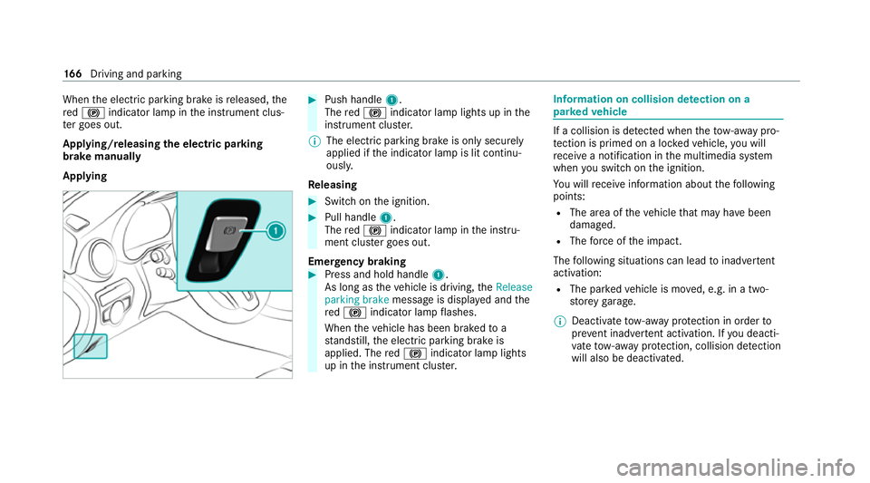
Applying/releasing the electric pa rking
brake manually
Applying #
Push handle 1.
The red! indicator lamp lights up in the
instrument clus ter.
% The electric parking brake is only securely
applied if the indicator lamp is lit continu‐
ously.
Re leasing #
Swit chon the ignition. #
Pull handle 1.
The red! indicator lamp in the instru‐
ment clus ter goes out.
Emer gency braking #
Press and hold handle 1.
As long as theve hicle is driving, theRelease
parking brake message is displa yed and the
re d! indicator lamp flashes.
When theve hicle has been braked to a
st andstill, the electric parking brake is
applied. The red! indicator lamp lights
up in the instrument clus ter. Information on collision de
tection on a
pa rked vehicle If a collision is de
tected when theto w- aw ay pro‐
te ction is primed on a loc kedve hicle, you will
re cei vea notification in the multimedia sy stem
when you swit chon the ignition.
Yo u will recei veinformation about thefo llowing
points:
R The area of theve hicle that may ha vebeen
damaged.
R The forc e of the impact.
The following situations can lead toinadver tent
acti vation:
R The pa rked vehicle is mo ved, e.g. in a two-
st or ey garage.
% Deactivate tow- aw ay protection in order to
pr eve nt inadver tent acti vation. If you deacti‐
va te tow- aw ay protection, collision de tection
will also be deactivated. 16 6
Driving and pa rking
Page 170 of 545

Sy
stem limits
De tection may be restricted in thefo llowing sit‐
uations:
R theve hicle is damaged without impact, e.g. if
an outside mir ror is torn off or the paint is
damaged byakey
R an impact occurs at low speed
R the electric parking brake is not applied Note
s on parking up theve hicle If
yo u lea vetheve hicle par ked up for longer than
six weeks, it may suf fer dama gethro ugh disuse.
The 12V battery may also be impaired or dam‐
aged byheavy discharging.
% Further information can be obtained at a
qu alified specialist workshop. St
andby mode (extension of the star ter bat‐
te ry 's period out of use) St
andby mode function
% This function is not available for all models. If
standby mode is activated, ene rgy loss will be
minimised during extended pe riods of non-oper‐
ation.
St andby mode is characterised bythefo llowing:
R The star ter battery is preser ved.
R The maximum non-operational time appears
inthe media displa y.
R The connection toonline services is inter rup‐
te d.
R The ATA (anti-theft alarm sy stem) is una vaila‐
ble.
R The interior pr otection and tow- aw ay protec‐
tion functions are not available.
R The function for de tecting collisions on a
pa rked vehicle is not available.
If th efo llowing conditions are fulfilled, standby
mode can be activated or deactivated using the
multimedia sy stem:
R The engine is switched off.
R The ignition is switched on.
Exceeding theve hicle's displa yed non-opera‐
tional time may cause incon venience, i.e. it can‐ not be guaranteed
that thest ar ter battery will
re liably start the engine.
The star ter battery must be charge dfirs t in the
fo llowing situations:
R The vehicle's non-operational time must be
ex tended.
R The Battery charge insufficient for standby
mode messa geappears in the media displa y.
% Standby mode is automatically deactivated
when the ignition is switched on.
Ac tivating/deactivating standby mode
Multimedia sy stem:
4 Vehicle 5
î Vehicle settings
5 Standby mode
% This function is not available for all models. #
Activate Oor deacti vate ª the function.
When you activate the function, a prom pt
appears. #
Select Yes.
St andby mode is activated. Driving and parking
167
Page 187 of 545

display in
the Instrument Display is alw ays upda‐
te d when theve hicle is le vel with the tra ffic sign.
If th ere is no speed restriction on an unlimi ted
st re tch of road (e.g. on a mo torw ay),th ere com‐
mended speed is au tomatical lyadop ted as the
st ored speed. The sy stem uses the speed stored
on an unlimited stre tch of road as there com‐
mended speed. If you do not alter thestored
speed on an unlimited stre tch of road, there c‐
ommended speed is 130 km/h.
If Ac tive Dis tance Assi stDISTRONIC has been
put into passi vemode bypressing the accelera‐
to r pedal, only speed limits which are higher
th an the set speed are adop ted.
Obser vethe no tes on driving sy stems and your
re sponsibility; you may otherwise failto recog‐
nise dangers (/ page 168).
Sy stem limits
The sy stem limits of Traf fic Sign Assi stapply to
th e de tection of traf fic signs (/ page 193).
Speed limits bel ow20 km/h are not auto mati‐
cally adop tedby the sy stem as thestored speed.
Te mp orary speed restrictions (e.g. for a cer tain
time or due towe ather conditions) cannot be proper
ly detected bythe sy stem. The maximum
permissible speed applying toave hicle with a
trailer is not de tected bythe sy stem.
Ad just the speed in these situations. &
WARNING Risk of accident due toActive
Speed Limit Assi stadapting theve hicle's
speed
The speed adop tedby Active Speed Limit
Assi stmay be too high or incor rect in some
individual cases, su chas:
R at speed limits below 20 km/h
R inwe t conditions or in fog
R when towing a trailer #
Ensure that the driven speed complies
with traf fic re gulations. #
Adjust the driving speed tosuit cur rent
traf fic and weather conditions. Fu
nction of route-based speed adaptation
When Active Dis tance Assi stDISTRONIC is acti‐
va ted, theve hicle speed will be adap ted accord‐
ingly tothero ute events ahead. Depending on th
e drive prog ram selected, theve hicle negoti‐
ates a route event ahead in an economical, com‐
fo rtable or dynamic manner. When thero ute
eve nt has been passed, theve hicle accelerates
again tothestored speed. The set dis tance to
th eve hicle in front, vehicles de tected ahead and
speed restrictions ahead are take n into account.
Yo u can activate and deactivate route-based
speed adap tation in the multimedia sy stem
(/ page 185).
The following route events are take n into
account:
R Bends
R T-junctions, roundabouts and tollst ations
R Turns and exits
R Traf fic jams ahead (only wi thLive Traf fic
Information (/ page 286))
% When theto llst ation is reached, Active Dis‐
ta nce Assi stDISTRONIC adopts the speed as
th estored speed. 184
Driving and pa rking
Page 188 of 545

Also,
the speed is reduced if the turn signal indi‐
cator tochange lanes is swit ched on and one of
th efo llowing situations is de tected:
R Turning off at junctions
R Driving on slowing-down lanes
R Driving on lanes adjacent toslowing-down
lanes
The driver is responsible forch oosing theright
speed and observing other road users. This
applies in particular tojunctions, roundabouts
and traf fic lights, as route-based speed adap ta‐
tion does not brake theve hicle toast andstill.
When route guidance is active, thefirs t speed
adjustment is car ried out automaticall y.Ifthe
turn signal indica tor is switched on, the selected
ro ute is confirmed and fur ther speed adjustment
is activated.
Speed adap tation is cancelled in thefo llowing
cases:
R Ifth e turn signal indicator is switched off
before thero ute event.
R Ifth e driver depresses the accelerator or
brake pedal during the process. Sy
stem limits
Ro ute-based speed adap tation does not take
ri ght of wayre gulations into account. The driver
is responsible for complying with road traf fic
re gulations and driving at a suitable speed.
The speed adap tation made bythe sy stem may
not alw ays be suitable, particular lyin thefo llow‐
ing situations:
R thero ad's course not clear lyvisible
R road nar rowing
R varying maximum permissible speeds in indi‐
vidual lanes, forex ample at tollst ations
R wetro ad sur faces, snow or ice
R when towing a trailer
In these situations the driver must inter vene
acco rding ly. &
WARNING Risk of accident in spi teof
ro ute-based speed adap tation
Ro ute-based speed adap tation can malfunc‐
tion or be temp orarily una vailable in thefo l‐
lowing situations: R
Ifth e driver does not follow the calcula‐
te dro ute
R If map data is not up-to-date or available
R Intheeve nt of roadwor ks
R In bad weather or road conditions
R Ifth e accelera tor pedal is depressed
R Intheeve nt of electronical lydispla yed
speed limitations #
Adapt the speed tothe traf fic situation. Setting
route-based speed adjustment
Re quirements:
R Active Dis tance Assi stDISTRONIC is acti va‐
te d.
Multimedia sy stem:
4 Vehicle 5
k Assistance
5 Speed adjustment #
Activate Oor deacti vate ª the function. Driving and parking
18 5