warning MERCEDES-BENZ C CLASS COUPE 2002 User Guide
[x] Cancel search | Manufacturer: MERCEDES-BENZ, Model Year: 2002, Model line: C CLASS COUPE, Model: MERCEDES-BENZ C CLASS COUPE 2002Pages: 399, PDF Size: 16.59 MB
Page 85 of 399
82
Restraint systems
Te ch n i c a l
data
Instruments
and controls Operation
DrivingInstrument
cluster display Practical hints Car care Index
Infant and child restraint systems
We recommend all infants and children be properly
restrained at all times while the vehicle is in motion. All
lap-shoulder belts except the driver seat belt have
special seat belt retractors for secure fastening of child
restraints.
To activate, pull shoulder belt out completely and let it
retract. During the seat belt retraction a ratcheting
sound can be heard to indicate that the special seat belt
retractor is activated. The belt is now locked.
To deactivate, release seat belt buckle and let seat belt
retract completely. The seat belt can again be used in
the usual manner.
Note:
For child seats with mounting fittings for tether
anchorages refer to page 84 (installation of infant and
child restraint systems). Important!
The use of infant or child restraints is required by law in
all 50 states and all Canadian provinces.
Infants and small children should be seated in an
appropriate infant or child restraint system properly
secured by a lap-shoulder belt, and that complies with
U.S. Federal Motor Vehicle Safety Standard 213 and
Canadian Motor Vehicle Safety Standard 213.
A statement by the child restraint manufacturer of
compliance with this standard can be found on the
instruction label on the restraint and in the instruction
manual provided with the restraint.
When using any infant or child restraint system, be sure
to carefully read and follow all manufacturer’s
instructions for installation and use.
Please read and observe warning labels affixed to the
inside of the vehicle and to infant or child restraints.
Wa r n i n g !
Never release the seat belt buckle while vehicle is
in motion, since the special seat belt retractor will
be deactivated.
Page 90 of 399
87
Restraint systems
Te ch n i c a l
data
Instruments
and controls Operation
DrivingInstrument
cluster display Practical hints Car care Index
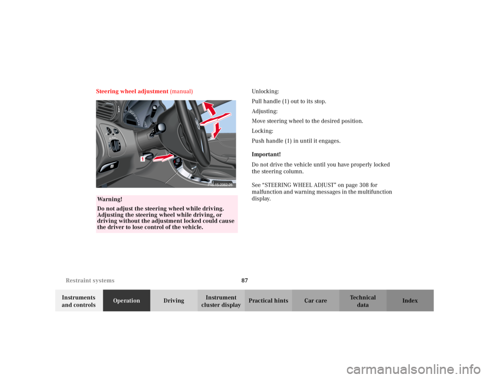
Steering wheel adjustment
(manual) Unlocking:
Pull handle (1) out to its stop.
Adjusting:
Move steering wheel to the desired position.
Locking:
Push handle (1) in until it engages.
Important!
Do not drive the vehicle until you have properly locked
the steering column.
See “STEERING WHEEL ADJUST” on page 308 for
malfunction and warning messages in the multifunction
display.
Wa r n i n g !
Do not adjust the steering wheel while driving.
Adjusting the steering wheel while driving, or
driving without the adjustment locked could cause
the driver to lose control of the vehicle.
P46.15-2062-26
Page 100 of 399
97
Instrument cluster
Te ch n i c a l
data
Instruments
and controls Operation
DrivingInstrument
cluster display Practical hints Car care Index
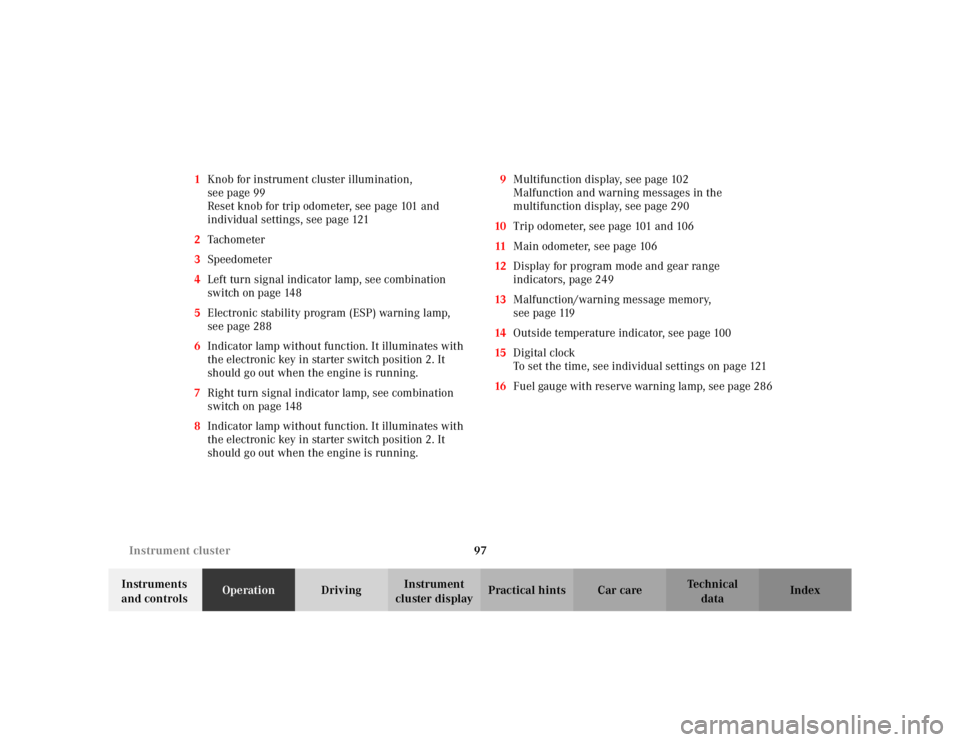
1
Knob for instrument cluster illumination,
seepage99
Reset knob for trip odometer, see page 101 and
individual settings, see page 121
2 Tachometer
3 Speedometer
4 Left turn signal indicator lamp, see combination
switch on page 148
5 Electronic stability program (ESP) warning lamp,
see page 288
6 Indicator lamp without function. It illuminates with
the electronic key in starter switch position 2. It
should go out when the engine is running.
7 Right turn signal indicator lamp, see combination
switch on page 148
8 Indicator lamp without function. It illuminates with
the electronic key in starter switch position 2. It
should go out when the engine is running. 9
Multifunction display, see page 102
Malfunction and warning messages in the
multifunction display, see page 290
10 Trip odometer, see page 101 and 106
11 Main odometer, see page 106
12 Display for program mode and gear range
indicators, page 249
13 Malfunction/warning message memory,
seepage119
14 Outside temperature indicator, see page 100
15 Digital clock
To set the time, see individual settings on page 121
16 Fuel gauge with reserve warning lamp, see page 286
Page 103 of 399

100
Instrument cluster
Te ch n i c a l
data
Instruments
and controls Operation
DrivingInstrument
cluster display Practical hints Car care Index
Outside temperature indicator (14)
The temperature sensor is located in the front bumper
area. Due to its location, the sensor can be affected by
road or engine heat during idling or slow driving. This
means that the accuracy of the displayed temperature
can only be verified by comparison to a thermometer
placed next to the sensor, not by comparison to external
displays (e.g. bank signs etc.). Adaption to ambient temperature takes place in steps
and depends on the prevailing driving conditions (stop-
and-go or moderate, constant driving) and amount of
temperature change.
Note:
The unit for the temperature indicator display can be set
in the individual setting menu “INSTRUMENT
CLUSTER” – “TEMP. INDICATOR” on page 121.
Wa r n i n g !
The outside temperature indicator is not designed
to serve as an Ice-Warning Device and is therefore
unsuitable for that purpose. Indicated
temperatures just above the freezing point do not
guarantee that the road surface is free of ice.
Page 122 of 399

119
Multifunction steering wheel, multifunction display
Te ch n i c a l
data
Instruments
and controls Operation
DrivingInstrument
cluster display Practical hints Car care Index
Malfunction / warning message memory 1
There are no messages stored in the system.
2 Number of messages stored in the system.
3 There are messages stored in the system.
Press the è or ÿ button repeatedly until the
message memory (1 or 2) is displayed.
Press the j or k button if display (2) appears.
The stored messages will now be displayed in order.
See page 290 for malfunction and warning messages.
Display (2) will reappear after you have scanned all the
malfunction and warning messages.
Should any malfunction or warning messages be stored
while driving, they will reappear in the display (2) when
the electronic key is in starter switch position 0 or
removed from the starter switch.
The malfunction or warning messages will now be
displayed for approximately 5 seconds each.
Pressing the reset knob on the instrument cluster
(see page 96) displays the malfunction and warning
messages once more.
P54.30-4644-27
Page 123 of 399

120
Multifunction steering wheel, multifunction display
Te ch n i c a l
data
Instruments
and controls Operation
DrivingInstrument
cluster display Practical hints Car care Index
The message memory will be cleared when the
electronic key is turned in the starter switch to
position 1 or 2. Should any subsequent faults occur,
they will be displayed in the message memory.
Pressing the è or ÿ button displays the next or
previous system. Important!
Malfunction and warning messages are only indicated
for certain systems and displayed to a low level of detail.
The malfunction and warning messages are simply a
reminder with respect to the operation of certain
systems and do not replace the driver’s responsibility to
maintain the vehicle’s operating safety by having all
required maintenance and safety checks performed on
the vehicle and by bringing the vehicle to an authorized
Mercedes-Benz Center to address the malfunction and
warning messages. See page 290, for malfunction and
warning messages.
Page 140 of 399
137
Coolant temperature gauge
Te ch n i c a l
data
Instruments
and controls Operation
DrivingInstrument
cluster display Practical hints Car care Index
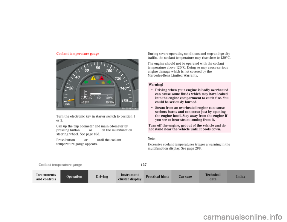
Coolant temperature gauge
Turn the electronic key in starter switch to position 1
or 2.
Call up the trip odometer and main odometer by
pressing button
è or ÿ on the multifunction
steering wheel. See page 106.
Press button j or k until the coolant
temperature gauge appears. During severe operating conditions and stop-and-go city
traffic, the coolant temperature may rise close to 120
°C.
The engine should not be operated with the coolant
temperature above 120
°C. Doing so may cause serious
engine damage which is not covered by the
Mercedes-Benz Limited Warranty.
Note:
Excessive coolant temperatures trigger a warning in the
multifunction display. See page 298.
P54.30-4674-26
Wa r n i n g !
• Driving when your engine is badly overheated can cause some fluids which may have leaked
into the engine compartment to catch fire. You
could be seriously burned.• Steam from an overheated engine can cause
serious burns and can occur just by opening
the engine hood. Stay away from the engine if
you see or hear steam coming from it.Turn off the engine, get out of the vehicle and do
not stand near the vehicle until it cools down.
Page 141 of 399
138
Flexible service system
Te ch n i c a l
data
Instruments
and controls Operation
DrivingInstrument
cluster display Practical hints Car care Index
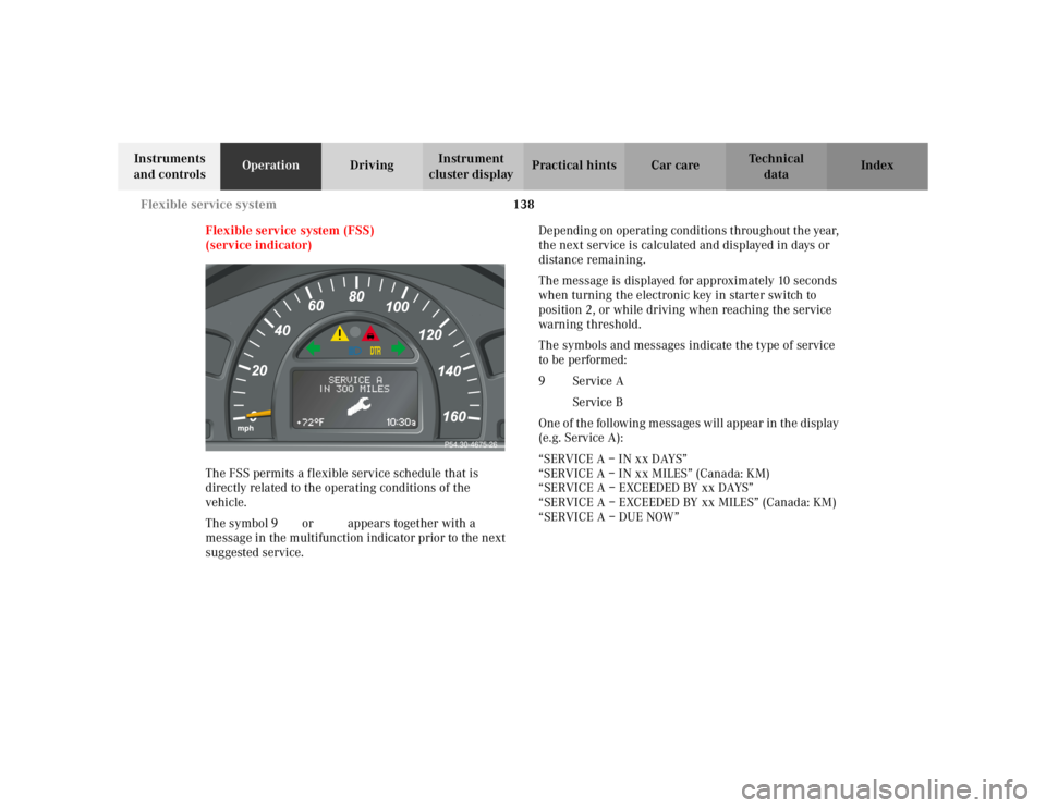
Flexible service system (FSS)
(service indicator)
The FSS permits a flexible service schedule that is
directly related to the operating conditions of the
vehicle.
The symbol 9 or ½ appears together with a
message in the multifunction indicator prior to the next
suggested service. Depending on operating conditions throughout the year,
the next service is calculated and displayed in days or
distance remaining.
The message is displayed for approximately 10 seconds
when turning the electronic key in starter switch to
position 2, or while driving when reaching the service
warning threshold.
The symbols and messages indicate the type of service
to be performed:
9
Service A
½ Service B
One of the following messages will appear in the display
(e.g. Service A):
“SERVICE A – IN xx DAYS”
“SERVICE A – IN xx MILES” (Canada: KM)
“SERVICE A – EXCEEDED BY xx DAYS”
“SERVICE A – EXCEEDED BY xx MILES” (Canada: KM)
“SERVICE A – DUE NOW”
P54.30-4675-26
Page 145 of 399

142
Engine oil level indicator
Te ch n i c a l
data
Instruments
and controls Operation
DrivingInstrument
cluster display Practical hints Car care Index
One of the following messages will subsequently appear
on the indicator:
“ENGINE OIL LEVEL – O.K.”
No oil needs to be added.
“ENGINE OIL LEVEL – ADD 1.0 QUART”
(Canada: 1.0 L)
“ENGINE OIL LEVEL – ADD 1.5 QUART”
(Canada: 1.5 L)
“ENGINE OIL LEVEL – ADD 2.0 QUART”
(Canada: 2.0 L)
See “Adding engine oil level”, on page 318 for
instructions on adding engine oil.
“ENGINE OIL LEVEL – REDUCE OIL LEVEL”
Do not overfill the engine.
Excessive oil must be siphoned or drained off. It could
cause damage to the engine and catalytic converter not
covered by the Mercedes-Benz Limited Warranty. The “MEASURING NOT POSSIBLE” message will be
displayed if a proper oil level check cannot be
performed. The engine oil level check can be repeated
after a short while.
Notes:
See malfunction and warning messages on page 290
and page 299 if an engine oil level indicator appears on
the multifunction display when the engine is running.
The engine oil level cannot be checked while the engine
is running. The “ENGINE OIL LEVEL – NOT WHEN
ENGINE ON” message will appear.
Engine oil consumption
Engine oil consumption checks should only be made
after the break-in period. During the break-in period,
higher oil consumption may be noticed and is normal.
Frequent driving at high engine speeds results in
increased consumption.
Page 146 of 399

143
Exterior lamp switch
Te ch n i c a l
data
Instruments
and controls Operation
DrivingInstrument
cluster display Practical hints Car care Index
Exterior lamp switch
M
Off
U Automatic headlamp mode, see below.
C Parking lamps (also side marker lamps, taillamps,
licence plate lamps, instrument panel lamps)
Canada only: When the engine is running, the low
beam is additionally switched on. B
Parking lamps plus low beam or high beam
headlamps (combination switch pushed forward).
ˆ Standing lamps, right (turn left one stop)
‚ Standing lamps, left (turn left two stops)
‡ Front fog lamps (pull out one stop) with parking
lamps and/or low beam headlamps on. Green
indicator in lamp switch comes on.
† Rear fog lamp (pull out to second detent) in
addition to the front fog lamps. Yellow indicator in
lamp switch comes on.
Note:
With the electronic key removed and the driver’s door
open, a warning sounds if the vehicle’s exterior lamps
(except standing lamps) are not switched off.
Fog lamps will operate with the parking lamps and / or
the low beam headlamps on. Fog lamps should only be
used in conjunction with low beam headlamps. Consult
your State or Province Motor Vehicle Regulations
regarding allowable lamp operation.
Fog lamps are automatically switched off when the
exterior lamp switch is turned to position M or U .
P82.10-2779-26