sunroof MERCEDES-BENZ C-CLASS COUPE 2011 User Guide
[x] Cancel search | Manufacturer: MERCEDES-BENZ, Model Year: 2011, Model line: C-CLASS COUPE, Model: MERCEDES-BENZ C-CLASS COUPE 2011Pages: 373, PDF Size: 8.17 MB
Page 96 of 373

ment feature is deactivated. Make sure that
nobody can become trapped when closing the
sliding sunroof.
If the sliding sunroof is obstructed during
closing and reopens again slightly:
X Immediately after the sliding sunroof
blocks, pull the 3switch in the over-
head control panel down to the point of
resistance and hold it until the sliding sun-
roof is closed.
The sliding sunroof is closed with increased
force.
If the sliding sunroof is obstructed again dur-
ing closing and reopens again slightly:
X Immediately after the sliding sunroof
blocks, pull the 3switch in the over-
head control panel down to the point of
resistance and hold it until the sliding sun-
roof is closed.
The sliding sunroof is closed withou tthe
anti-entrapment feature. Sliding sunroof
93Opening and closing Z
Page 104 of 373
X
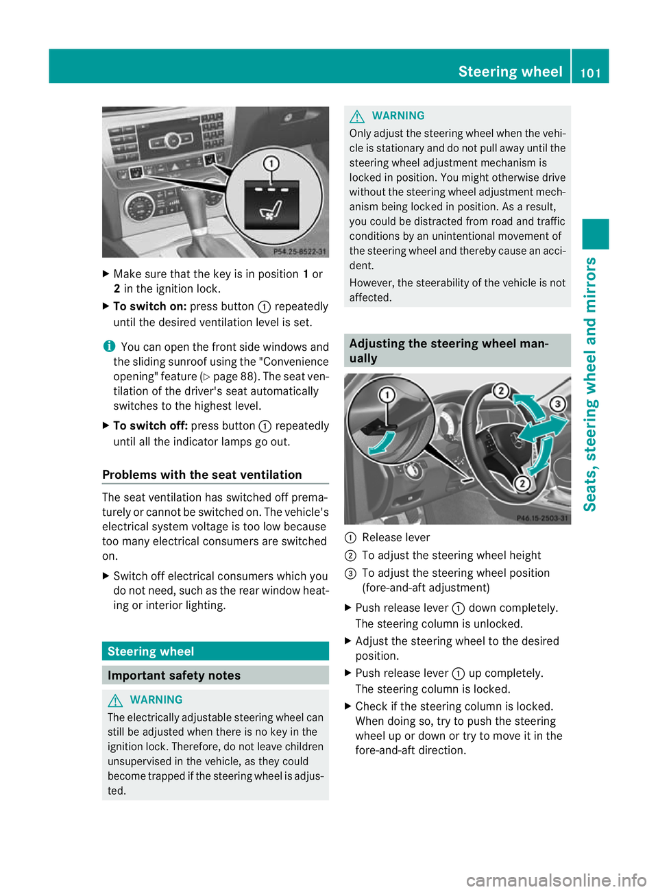
Make sure that the key is in position 1or
2 in the ignition lock.
X To switch on: press button:repeatedly
until the desired ventilation level is set.
i You can open the front side windows and
the sliding sunroof using the "Convenience
opening" feature (Y page 88). The seat ven-
tilation of the driver's seat automatically
switches to the highest level.
X To switch off: press button:repeatedly
until all the indicator lamps go out.
Problems with the seat ventilation The seat ventilation has switched off prema-
turely or cannot be switched on. The vehicle's
electrical system voltage is too low because
too many electrical consumers are switched
on.
X Switch off electrical consumers which you
do not need, such as the rear window heat-
ing or interior lighting. Steering wheel
Important safety notes
G
WARNING
The electrically adjustable steering wheel can
still be adjusted when there is no key in the
ignition lock. Therefore, do not leave children
unsupervised in the vehicle, as they could
become trapped if the steering wheel is adjus-
ted. G
WARNING
Only adjust the steering wheel when the vehi-
cle is stationary and do not pull away until the
steering wheel adjustment mechanism is
locked in position. You might otherwise drive
without the steering wheel adjustment mech-
anism being locked in position. As a result,
you could be distracted from road and traffic
conditions by an unintentional movement of
the steering wheel and thereby cause an acci-
dent.
However, the steerability of the vehicle is not
affected. Adjusting the steering wheel man-
ually
:
Release lever
; To adjust the steering wheel height
= To adjust the steering wheel position
(fore-and-aft adjustment)
X Push release lever :down completely.
The steering column is unlocked.
X Adjust the steering wheel to the desired
position.
X Push release lever :up completely.
The steering column is locked.
X Check if the steering column is locked.
When doing so, try to push the steering
wheel up or down or try to move it in the
fore-and-aft direction. Steering wheel
101Seats, steering wheel and mirrors Z
Page 125 of 373
Useful information
i This Owner's Manual describes all models
and all standard and optional equipment
available to your vehicle at the time of pub-
lication of the Owner's Manual. Country-
specific deviations are possible. Please
note that your vehicle may not be equipped
with all features described. This also
applies to safety-relevan tsystems and
functions.
i Please read the information on qualified
specialist workshops (Y page 26).Overview of climate control systems
Important safety notes
G
WARNING
Observe the settings recommended on the
following pages. Otherwise, th ewindows
could mist up. This may obstruct your view of
the traffic situation and, as a result, you may
cause an accident.
THERMATIC automatic climate control con-
trols the temperature and the humidity in the
vehicle interior and filters undesirable sub-
stances from the air.
THERMATIC automatic climate control is only
operational when the engine is running. Opti-
mum operation is only achieved when you
drive with the side windows and panorama
sliding sunroof closed.
i Ventilate the vehicle for a brief period
during warm weather, e.g. using the con-
venience opening feature (Y page 88). This
will speed up the cooling process and the
desired vehicle interior temperature will be
reached more quickly.
i The integrated filter can filter out most
particles of dust and completely filters out
pollen .Aclogged filter reduces the amount
of air supplied to the vehicle interior .For
this reason, you should always observe the
interval for replacing the filter, which is specified in the Service Booklet
.As it
depends on environmental conditions, e.g.
heavy air pollution, the interval may be
shorter than stated in the Service Booklet.
i It is possible that the residual heat func-
tion may be activated automatically an hour
after the key is removed. The vehicle is then
ventilated for 30 minutes to dry the air-
conditioning system. 122
Overview of climate control systemsClimate control
Page 130 of 373
Problems with the rear window heating
The rear window heating has switched off
prematurely or cannot be activated.
X Switch off any consumers that are not
required, e.g. reading lamps or interior
lighting.
When the battery is sufficiently charged,
the rear window heating is activated again
automatically. Activating/deactivating air-recircula-
tion mode
You can deactivate the flow of fresh air if
unpleasant odours are enteringt he vehicle
from outside. The air already inside the vehi-
cle will then be recirculated. G
WARNING
Only switch over to air-recirculation mode
briefly at low outside temperatures. Other-
wise, the windows could mist up, thus impair-
ing visibility and endangering yourself and
others. This may prevent you from observing
the traffic conditions, thereby causing an
accident.
X Turn the key to position 2in the ignition
lock.
X To activate: press thegbutton.
The indicator lamp in the gbutton lights
up.
i In the event of high pollution levels or at
high outside temperatures, air-recircula-
tion mode is automatically activated. When
air-recirculation mode is activated auto-
matically, the indicator lamp in the g
button is not lit.
Outside air is added after about 30
minutes.
X To switch off: press thegbutton.
The indicator lamp in the gbutton goes
out. Convenience opening/closing using
the air-recirculation button
G
WARNING
Make sure that nobody can become trapped
between the side window and the door frame
as the side windows are opened and closed.
Make sure that all objectsa nd body parts are
clear of the side windows when they are being
opened or closed .You or the objects could be
drawn in or become trapped between the side
window and the door frame as the window
moves. If there is arisk of entrapment, oper-
ate the Wswitch to move the side window
in the opposite direction.
Make sure that nobody can become trapped
as the panorama sliding sunroof is opened
and closed. If there is a risk of entrapment,
operate the 3switch to move the pano-
rama sliding sunroof in the opposite direction.
X Convenience closing feature: press and
hold the gbutton until the side win-
dows and the panorama sliding sunroof are
closed.
The indicator lamp in the gbutton lights
up. Air-recirculation mode is activated.
X Convenience opening feature: press and
hold the gbutton until the side win-
dows and the panorama sliding sunroof
have opened. The side windows and the
panorama sliding sunroof move back to
their original position.
The indicator lamp in the gbutton goes
out. Air-recirculation mode is deactivated.
i If you open the side windows or the pan-
orama sliding sunroof manually after clos-
ing with the convenience closing feature,
they will remain in this position when
opened using the convenience opening fea-
ture. Operating the climate control system
127Climate control Z
Page 291 of 373
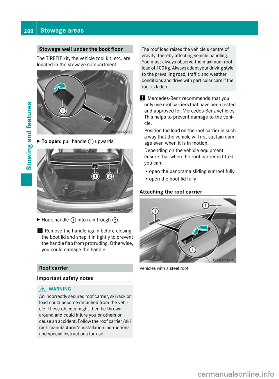
Stowage well under the boot floor
The TIREFIT kit, the vehicle tool kit, etc. are
located in the stowage compartment. X
To open: pull handle :upwards. X
Hook handle :into rain trough ;.
! Remove the handle again before closing
the boot lid and snap it in tightly to prevent
the handle flap from protruding. Otherwise,
you could damage the handle. Roof carrier
Important safety notes G
WARNING
An incorrectly secured roof carrier, ski rack or
load could become detached from the vehi-
cle. These objects might then be thrown
around and could injure you or others or
cause an accident. Follow the roof carrier/ski
rack manufacturer's installation instructions
and special instructions for use. The roof load raises the vehicle's centre of
gravity, thereby affecting vehicle handling.
You must always observe the maximum roof
load of 100 kg. Always adapt your driving style
to the prevailing road, traffic and weather
conditions and drive with particular care if the
roof is laden.
! Mercedes-Benz recommends that you
only use roof carriers that have been tested
and approved for Mercedes-Benz vehicles.
This helps to prevent damage to the vehi-
cle.
Position the load on the roof carrier in such
a way that the vehicle will not sustain dam-
age even when it is in motion.
Depending on the vehicle equipment,
ensure that when the roof carrier is fitted
you can:
R open the panorama sliding sunroof fully
R open the boot lid fully
Attaching the roof carrier Vehicles with a steel roof288
Stowage areasStowing and features
Page 292 of 373
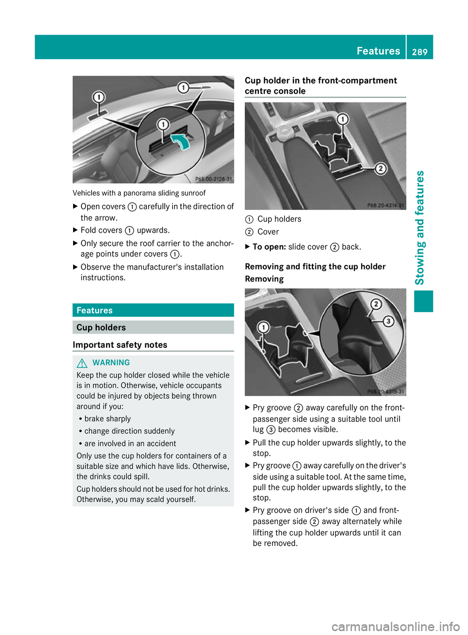
Vehicles with a panorama sliding sunroof
X
Open covers :carefully in the direction of
the arrow.
X Fold covers :upwards.
X Only secure the roof carrier to the anchor-
age points under covers :.
X Observe the manufacturer's installation
instructions. Features
Cup holders
Important safety notes G
WARNING
Keep the cup holder closed while the vehicle
is in motion. Otherwise, vehicle occupants
could be injured by objects being thrown
around if you:
R brake sharply
R change direction suddenly
R are involved in an accident
Only use the cup holders for containers of a
suitable size and which have lids. Otherwise,
the drinks could spill.
Cup holders should not be used for hot drinks.
Otherwise, you may scald yourself. Cup holder in the front-compartment
centre console
:
Cup holders
; Cover
X To open: slide cover ;back.
Removing and fitting the cup holder
Removing X
Pry groove ;away carefully on the front-
passenger side using a suitable tool until
lug =becomes visible.
X Pull the cup holder upwards slightly, to the
stop.
X Pry groove :away carefully on the driver's
side using a suitable tool. At the same time,
pull the cup holder upwards slightly, to the
stop.
X Pry groove on driver's side :and front-
passenger side ;away alternately while
lifting the cup holder upwards until it can
be removed. Features
289Stowing and features Z
Page 355 of 373
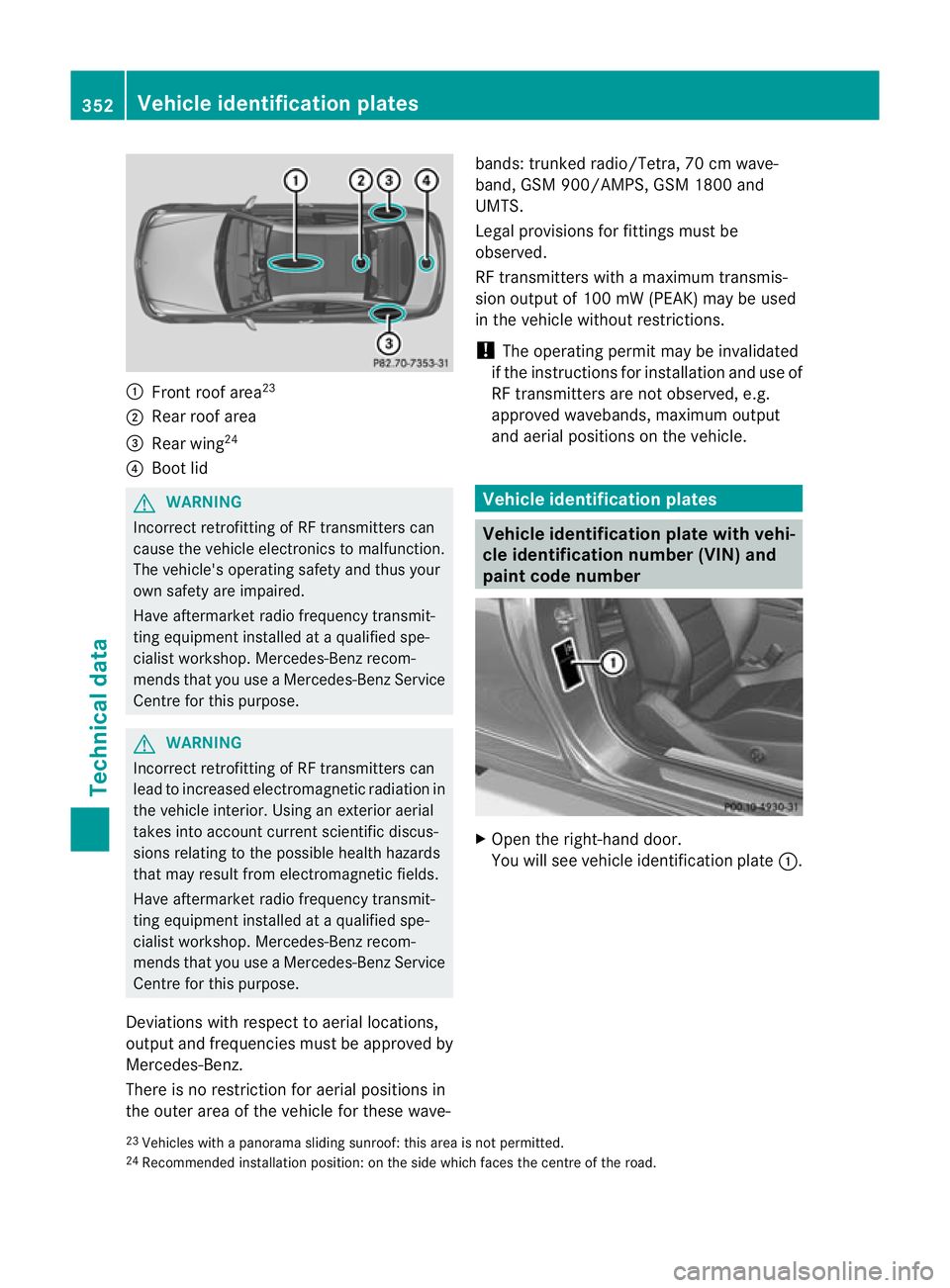
:
Front roof area 23
; Rear roof area
= Rear wing 24
? Boot lid G
WARNING
Incorrect retrofitting of RF transmitters can
cause the vehicle electronics to malfunction.
The vehicle's operating safety and thus your
own safety are impaired.
Have aftermarket radio frequency transmit-
ting equipment installed at a qualified spe-
cialist workshop .Mercedes-Benz recom-
mends that you use a Mercedes-Benz Service
Centre for this purpose. G
WARNING
Incorrect retrofitting of RF transmitters can
lead to increased electromagnetic radiation in
the vehicle interior. Using an exterior aerial
takes into account current scientific discus-
sions relating to the possible health hazards
that may result from electromagnetic fields.
Have aftermarket radio frequency transmit-
ting equipment installed at a qualified spe-
cialist workshop. Mercedes-Benz recom-
mends that you use a Mercedes-Benz Service
Centre for this purpose.
Deviations with respect to aerial locations,
output and frequencies must be approved by
Mercedes-Benz.
There is no restriction for aerial positions in
the outer area of the vehicle for these wave- bands: trunked radio/Tetra, 70 cm wave-
band, GSM 900/AMPS, GSM 1800 and
UMTS.
Legal provisions for fittings must be
observed.
RF transmitters with a maximum transmis-
sion output of 100 mW (PEAK) may be used
in the vehicle without restrictions.
!
The operating permit may be invalidated
if the instructions for installation and use of
RF transmitters are not observed, e.g.
approved wavebands, maximum output
and aerial positions on the vehicle. Vehicle identification plates
Vehicle identification plate with vehi-
cle identification number (VIN) and
paint code number
X
Open the right-hand door.
You will see vehicle identification plate :.
23 Vehicles with a panorama sliding sunroof :this area is not permitted.
24 Recommended installation position: on the side which faces the centre of the road. 352
Vehicle identification platesTechnical data