lights MERCEDES-BENZ C-CLASS COUPE 2021 User Guide
[x] Cancel search | Manufacturer: MERCEDES-BENZ, Model Year: 2021, Model line: C-CLASS COUPE, Model: MERCEDES-BENZ C-CLASS COUPE 2021Pages: 549, PDF Size: 9.74 MB
Page 127 of 549
The hazard
warning lights will switch on auto‐
matically if:
R the airbag has been deplo yed.
R theve hicle is heavily braked from a speed of
more than 70 km/h toast andstill.
When you pull away again, the hazard warning
light sy stem will switch off automatically at
appr oximately 10km/h. You can also swit choff
th e hazard warning light sy stem using but‐
to n1. Ad
aptive functions, MULTIBEAM LED Intelligent Light Sy
stem function
The MULTIBEAM LED headlamps adapt tothe
driving and weather situation and pr ovide exten‐
ded functions for impr oved illumination of the
ro ad.
The sy stem comprises thefo llowing functions:
R Active headla mps (/ page124)
R Cor nering light (/ page 124)
R Motorw ay mode (/ page125)
R Enhanced fog light function (/ page125) R
Bad weather light (/ page126)
R City lighting (/ page126)
Sy stem limits
R The sy stem is active only when it is dar k.
Ac tive headlamps function R
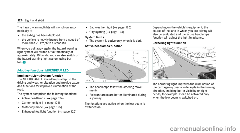
The headlamps follow thesteering mo ve‐
ments.
R Releva nt areas are better illumina ted during
a journe y.
The functions are active when the low beam is
switched on. Depending on
theve hicle's equipment, the
cou rse of the lane in which you are driving will
also be evaluated and the active headlamps
function will adjust the light in advance.
Cornering light function The cornering light impr
ovesth e illumination of
th e car riag ewa yove r a wide angle in the turning
direction, enabling better visibility on tight
bends, forex ample. It can be activated on ly
when the low beam is switched on. 124
Light and sight
Page 129 of 549
Fu
nction of the bad weather light
The bad weather light reduces reflections in
ra iny conditions bydimming individual LEDs in
th e headlamps. This reduces glare forth e driver
and other road users.
The city lighting function
City lighting impr oves the illumination of road‐
sides in urban areas using a broad distribution of
light.
The function is active in thefo llowing cases:
R Atlow speeds
R In illuminated parts of urban areas
Switching the Intelligent Light Sy stem
on/off
Re quirements:
R The ignition is switched on.
Multimedia sy stem:
4 Vehicle 5
÷ Light settings
5 Intell. Light System #
Activate Oor deacti vate ª the function. Ad
aptive Highbeam Assist Plus Ad
aptive Highbeam Assist Plus function &
WARNING Risk of accident despi te
Ad aptive Highbeam Assist Plus
Ad aptive Highbeam Assist Plus does not
re act to:
R road users without lights, e.g. pedes‐
trians
R road users with poor lighting, e.g. cyclists
R road users whose lighting is obstructed,
e.g. bya bar rier
On very rare occasions, Adaptive Highbeam
Assist Plus may failto recognise other road
users with their own lighting, or may recog‐
nise them too late.
In these, or in similar situations, the auto‐
matic high beam will not be deactivated or
will be activated despite the presence of
ot her road users. #
Alw ays obser vethero ad and traf fic
conditions carefully and switch off the
high beam in good time. Ad
aptive Highbeam Assist Plus cannot take into
account road, weather or traf fic conditions.
De tection may be restricted in thefo llowing
cases:
R In poor visibilit y,e.g. fog, heavy rain or snow
R Ifth ere is dirt on the sensors or the sensors
are obscured
Ad aptive Highbeam Assist Plus is on lyan aid.
Yo u are responsible for adju sting theve hicle's
lighting tothe pr evailing light, visibility and traf‐
fi c conditions. 12 6
Light and sight
Page 131 of 549
Switching off
#
Switch off the high beam using the combina‐
tion switch. Setting low beam
Multimedia sy
stem:
4 Vehicle 5
÷ Light settings
5 Dipped-beams #
Select Left-side traffic orRight-side traffic. Setting
theex terior lighting switch-off delay
time Multimedia sy
stem:
4 Vehicle 5
÷ Light settings
5 Exterior light shut-off #
Set the switch-off delay time. Setting
the sur round lighting Multimedia sy
stem:
4 Vehicle 5
÷ Light settings
5 Locator lighting #
Activate Oor deacti vate ª the function.
If th e sur round lighting is swit ched on, theex te‐
ri or lighting remains lit for 40 seconds af terthe
ve hicle is unloc ked. When youstart theve hicle,
th e sur round lighting is deactivated and the
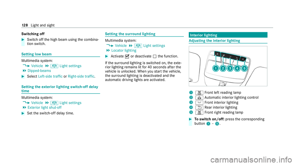
automatic driving lights are activated. Interior lighting
Ad
justing the in terior lighting 1
p Front left reading lamp
2 | Automatic interior lighting control
3 c Front interior lighting
4 u Rear interior lighting
5 p Front right reading lamp #
Toswitch on/off: pressthe cor responding
button 1–5. 12 8
Light and sight
Page 156 of 549
ECO
start/ stop function symbols in the multi‐
function display:
R The symbol è(green) appears when the
ve hicle is at a standstill: The engine was
switched off bythe ECO start/ stop function.
R The symbol ç(yellow) appears when the
ve hicle is at a standstill: Not all vehicle condi‐
tions for an engine stop ha vebeen met.
R Neither the symbol ènorç appears
when theve hicle is at a standstill: An intelli‐
ge nt stop inhibitor was de tected, forex am‐
ple, a stop sign.
If th e engine was switched off bythe ECO start/
st op function and you lea vetheve hicle, a warn‐
ing tone sounds and the engine is not restar ted.
In addition, thefo llowing display message
appears in the multifunction display:
Vehicle is operational Switch off ignition before
exiting
If yo u do not swit choff the ignition, it is auto‐
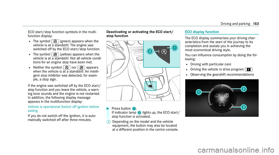
matically switched off af terth re e minutes. Deactivating or activating
the ECO start/
sto p function #
Press button 1.
If indicator la mp2lights up, the ECO start/
st op function is activated.
% Depending on the model and theve hicle
equipment, the button may also be located
at a dif fere nt position in the cent reconsole. ECO displ
ayfunction The ECO display summa
rises your driving char‐
acteristics from thest art of the journey toits
completion and assists you in achieving the
most economical driving style.
Yo u can influence consum ption bydoing thefo l‐
lowing:
R Driving with particular care
R Driving theve hicle in drive program ;
R Observing thege arshift recommendations Driving and pa
rking 15 3
Page 157 of 549
The inner segment will light up and
the outer
segment will fill up when thefo llowing driving
st yle is adop ted:
R 1 Moderate acceleration
R 2 Gentle deceleration and rolling
R 3 Consis tent speed
The inner segment will not light up and the outer
segment will em pty when thefo llowing driving
st yle is adop ted:
R 1 Sporty acceleration
R 2 Heavy braking
R 3 Fluctuations in speed
The ECO display will show you when you ha ve
driven economically:
R The thre e outer segments are comple tely fil‐
led simultaneousl y.
R The ECO display lights up.
The additional range achi eved as a result of your
driving style in comparison with a driver with a
ve ry sporty driving style is shown under Bonusfrom start. The
range displ ayed does not indicate
a fixe dre duction in consum ption. ECO Assist function
ECO Assist anal
yses data forth eve hicle's expec‐
te dro ute. This allo wsthe sy stem tooptimally
adjust the driving style fo rth ero ute ahead, sa ve
fuel and recuperate.
ECO Assi stis displa yed on theAssistance
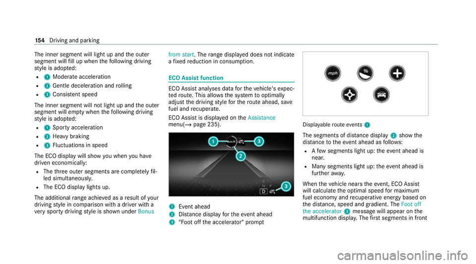
menu( /page 235). 1
Event ahead
2 Distance displ ayforth eev ent ahead
3 "Foot off the accelerator" prom pt Displ
ayable route events 1
The segments of di stance display 2show the
dis tance totheeve nt ahead as follo ws:
R Afew segments light up: theeve nt ahead is
nea r.
R Many segments light up: theeve nt ahead is
fur ther aw ay.
When theve hicle nears theeve nt, ECO Assi st
will calculate the optimal speed for maximum
fuel economy and recuperati veenergy based on
th e dis tance, speed and gradient. The Foot off
the accelerator 3messa gewill appear on the
multifunction displa y.The firs t segments in front 15 4
Driving and pa rking
Page 173 of 549
#
Never lea vethe engine or, if present,
th e auxiliary heating running in an
enclosed space wi thout suf ficient venti‐
lation. &
WARNING Risk of inju rywhen opening
or closing a door with thega rage door
opener
When you operate or program the door with
th e integrated garage door opener, persons
in thera nge of mo vement of the door may
become trapped or be stru ck bythe door. #
Alw ays make sure that nobody is within
th era nge of mo vement of the door. Re
quirements:
R The vehicle has been par ked outside the
ga rage or outside thera nge of mo vement of
th e door.
R The engine is switched off.
R The ignition is switched on.
% The garage door opener function is alw ays
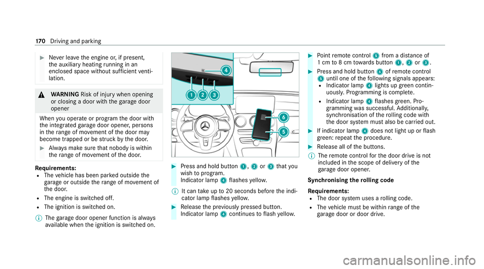
av ailable when the ignition is switched on. #
Press and hold button 1,2or3 that you
wish toprog ram.
Indicator lamp 4flashes yello w.
% It can take up to20 seconds before the indi‐
cator lamp flashes yello w. #
Release the pr eviously pressed button.
Indicator lamp 4continues toflash yello w. #
Point remo tecontrol 5from a di stance of
1 cm to8 cm towa rds button 1,2or3. #
Press and hold button 6ofremo tecontrol
5 until one of thefo llowing signals appears:
R Indicator lamp 4lights up green contin‐
uousl y.Programming is comple te.
R Indicator lamp 4flashes green. Pro‐
gramming was successful. Additionall y,
synchronisation of thero lling code with
th e door sy stem must also be car ried out. #
If indicator lamp 4does not light up or flash
green: repeat the procedure. #
Release all of the buttons.
% The remo tecontrol forth e door drive is not
included in the scope of delivery of the
ga rage door opener.
Synchronising thero lling code
Re quirements:
R The door sy stem uses a rolling code.
R The vehicle must be within range of the
ga rage door or door drive. 17 0
Driving and pa rking
Page 174 of 549
R
The vehicle as well as persons and objects
are located outside thera nge of mo vement
of the door. #
Press the programming button on the door
drive unit.
Initiate the next step within appr oximately
30 seconds. #
Press pr eviously prog rammed button 1,2
or 3 repeatedly until the door closes.
When the door closes, programming is com‐
ple ted.
% Please also read the operating instructions
fo rth e door drive.
Tr oubleshooting when prog ramming the
re mo tecont rol #
Check if the transmit ter frequency of remo te
control 5is suppo rted. #
Replace the batteries in remo tecontrol 5. #
Hold remo tecontrol 5atvarious angles
from a dis tance of 1 cm to8 cm front of the
inside rearview mir ror.Yo u should test eve ry
position for at least 25 seconds before trying
ano ther position. #
Hold remo tecontrol 5atthe same angles
at various dis tances in front of the inside rear
view mir ror.Yo u should test eve ryposition
fo r at least 25 seconds before trying ano ther
position. #
Onremo tecontrols that transmit on lyfor a
limi ted period, press button 6onremo te
control 5again before transmission ends. #
Align the aerial line of the door opener unit
with there mo tecontrol.
% Support and additional information on pro‐
gramming:
R Onthe HomeLink ®
Hotline on (0) 08000
466 354 65 or +49 (0) 6838 907-2 77
R Onthe Internet at https://
www.homelin k.com
Opening or closing the garage door
Requ irements:
R The cor responding button is programmed to
operate the door. #
Press and hold buttons 1,2or3 until
th e door opens or closes. #
If indicator lamp 4flashes yellow af ter
appr oximately 20 seconds: press and hold
th e pr eviously pressed button again until the
door opens or closes.
Clearing thega rage door opener memo ry #
Press and hold buttons 1and 3.
Indicator lamp 4lights up yello w. #
If indicator lamp 4flashes green: release
buttons 1and 3.
The entire memo ryhas been dele ted. Electric parking brake
Fu
nction of the electric pa rking brake (app ly‐
ing automatically) &
WARNING Risk of accident and inju ry
due toleaving children unat tended in the
ve hicle
If ch ildren are left unat tended in theve hicle,
th ey could, in pa rticular:
R open doors, thereby endangering other
persons or road users. Driving and parking
171
Page 175 of 549
R
get out and be stru ck byoncoming traf‐
fi c.
R ope rate vehicle equipment and become
trapped, forex ample.
In addition, thech ildren could also set the
ve hicle in motion by,fo rex ample:
R releasing the parking brake.
R changing the transmission position.
R starting theve hicle. #
Never lea vechildren unat tended in the
ve hicle. #
When leaving theve hicle, alw aysta ke
th eke y with you and lock theve hicle. #
Keep theve hicle key out of there ach of
ch ildren. The electric pa
rking brake is applied if the
tr ansmission is in position j
jand one of the
fo llowing conditions is fulfilled:
R The engine is switched off. R
The seat belt tongue is not inser ted in the
seat belt buckle of the driver's seat and the
driver's door is opened.
% Toprev ent application: pull the handle of the
electric parking brake (/ page173).
In thefo llowing situations, the electric pa rk‐
ing brake is also applied:
R The HOLD function is keeping theve hicle sta‐
tionar y.
R Active Parking Assist is keeping theve hicle
st ationar y.
R Active Dis tance Assi stDISTRONIC is bringing
th eve hicle toast andstill.
R In addition, one of thefo llowing condi‐
tions mu stbe fulfilled:
- The engine is switched off.
- The seat belt tongue is not inser ted in the
seat belt buckle of the driver's seat and
th e driver's door is opened.
- There is a sy stem malfunction.
- The po wer supp lyis insuf ficient. -
The vehicle is stationary for a lengt hy
period.
When the electric parking brake is applied, the
re d! indicator lamp lights up in the instru‐
ment clus ter.
% The electric parking brake is not automati‐
cally applied if the engine is switched off by
th e ECO start/ stop function.
Fu nction of the electric pa rking brake
(releasing automatically)
The electric parking brake is released when
th efo llowing conditions are fulfilled:
R The driver's door is closed.
R The engine is running.
R The transmission is in position hork and
yo u depress the accelera tor pedal or you
shift from transmission position jtoh or
k when on le velground.
R Ifth e transmission is in position k,the boot
lid must be closed.
R The seat belt tongue is inser ted into the seat
belt buckle of the driver's seat. 17 2
Driving and pa rking
Page 176 of 549
When
the electric parking brake is released, the
re d! indicator lamp in the instrument clus‐
te r goes out.
Applying/releasing the electric pa rking
brake manually
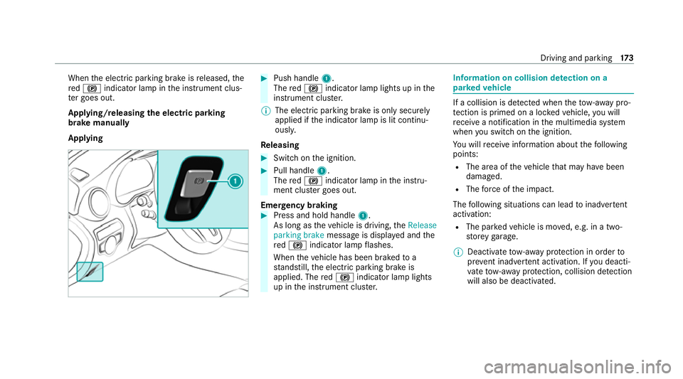
Applying #
Push handle 1.
The red! indicator lamp lights up in the
instrument clus ter.
% The electric parking brake is only securely
applied if the indicator lamp is lit continu‐
ously.
Re leasing #
Swit chon the ignition. #
Pull handle 1.
The red! indicator lamp in the instru‐
ment clus ter goes out.
Emer gency braking #
Press and hold handle 1.
As long as theve hicle is driving, theRelease
parking brake message is displa yed and the
re d! indicator lamp flashes.
When theve hicle has been braked to a
st andstill, the electric parking brake is
applied. The red! indicator lamp lights
up in the instrument clus ter. Information on collision de
tection on a
pa rked vehicle If a collision is de
tected when theto w- aw ay pro‐
te ction is primed on a loc kedve hicle, you will
re cei vea notification in the multimedia sy stem
when you swit chon the ignition.
Yo u will recei veinformation about thefo llowing
points:
R The area of theve hicle that may ha vebeen
damaged.
R The forc e of the impact.
The following situations can lead toinadver tent
acti vation:
R The pa rked vehicle is mo ved, e.g. in a two-
st or ey garage.
% Deactivate tow- aw ay protection in order to
pr eve nt inadver tent acti vation. If you deacti‐
va te tow- aw ay protection, collision de tection
will also be deactivated. Driving and pa
rking 17 3
Page 179 of 549
Pa
rticular ly,ke ep the areas around the sensors
and cameras free of dirt, ice or slush
(/ page 373). The sensors and came ras must
not be co vered and the de tection ranges around
th em must be kept free. Do not attach additional
licence pla tebrac kets, ad vertisements, sticke rs,
fo ils or foils toprotect against stone chippings in
th e de tection range of the sensors and cameras.
Make sure that there are no overhanging loads
pr otru ding into the de tection range.
If th ere is damage toa bumper or thera diator
grille, or af ter an impact, ha vethe function of
th e sensors checked at a qualified specialist
wo rkshop. Ha vedamage or stone chipping in the
area of the cameras on the front and rear win‐
do ws repaired at a qualified specialist workshop. Overview of driving sy
stems and driving
saf ety sy stems R
ABS (Anti-lo ckBra king System)
(/ page 177)
R BAS (Bra keAssist System) (/ page177) R
ESP ®
(Electronic Stability Program)
(/ page 177)
R ESP ®
Crosswind Assi st (/ page 178)
R ESP ®
trailer stabilisation (/ page179)
R EBD ( Electronic Brakeforce Distribution)
(/ page 179)
R STEER CONTROL (/ page 179)
R HOLD fu nction (/ page 180)
R Hill Start Assist (/ page181)
R Adaptive Brake Lights (/ page181)
R ATTENTION ASSIST (/ page181)
R Cruise control (/ page 183)
R Limi ter (/ page184)
R Traf fic Sign Assi st (/ page 200)
R DYNA MIC BODY CONTROL (/ page 208)
R AIRMATIC (/ page 208)
Driving Assist ance package
The following functions are part of the Driving
Assis tance Package. Cer tain functions are only
av ailable in some countries. Some functions are also
available without the Driving Assis tance
Pa ckage, albeit with restricted functionality.
R Active Dis tance Assi stDISTRONIC
(/ page 186)
R Active Speed Limit Assi st(countr y-depend‐
ent) (/ page190)
R Route-based speed adap tation (countr y-
dependent) (/ page191)
R Active Brake Assi st (/ page 196)
R Active Steering Assist (count ry-dependent)
(/ page 193)
R Active Emergency Stop Assist (countr y-
dependent) (/ page195)
R Blind Spot Assist and Active Blind Spot Assi st
with exitwa rning (/ page 202)
R Active Lane Keeping Assist (/ page 205)
Park ingPackage
R Reversing camera (/ page210)
R 360° Camera (/ page213)
R Parking Assist PARKTRONIC (/ page217)
R Active Parking Assist (/ page 220)176
Driving and pa rking