boot MERCEDES-BENZ C-CLASS COUPE 2021 Owner's Guide
[x] Cancel search | Manufacturer: MERCEDES-BENZ, Model Year: 2021, Model line: C-CLASS COUPE, Model: MERCEDES-BENZ C-CLASS COUPE 2021Pages: 549, PDF Size: 9.74 MB
Page 373 of 549
*
NO
TEDama gefrom auto matic braking If one of
thefo llowing functions is switched
on, theve hicle brakes automatically in cer‐
ta in situations:
R Active Brake Assi st
R Active Dis tance Assi stDISTRONIC
R HOLD function
R Active Parking Assist
To avo id damage totheve hicle, deactivate
th ese sy stems in thefo llowing or similar sit‐
uations: #
during towing #
in a car wash *
NO
TEDama gedue tounsuitable car
wa sh #
Before driving into a car wash make
sure that the car wash is suitable for
th eve hicle dimensions. #
Ensure there is suf ficient ground clear‐
ance between the underbody and the
guide rails of the car wash. #
Ensure that the clearance width of the
car wash, in particular the width of the
guide rails, is suf ficient. To
avo id damage to yourvehicle when using a
car wash, ensure thefo llowing beforehand:
R Active Dis tance Assi stDISTRONIC is deacti‐
va ted.
R the HOLD function is switched off.
R the 360° Camera or there ve rsing camera is
switched off.
R the side windo wsand sliding sun roof are
comple tely closed.
R the blo werfo rth eve ntilation/heating is
switched off.
R the windscreen wiper switch is in position
g.
R theke y is at a minimum dis tance of 3 m
aw ay from theve hicle. Otherwise the boot lid
could open unintentionally. R
for car washes with a con veyo r sy stem:
- neutral iis engaged.
- Ifyo uwo uld like tolea vetheve hicle while
it is being washed, make sure theke y is
located in theve hicle. The park position
j isotherwise automatically engaged.
% If, af terth e car wash, youre mo vethewax
from the windscreen and wiper rubbers, this
will pr event smearing and reduce wiper
noise. Information on using a high-p
ressure cleaner &
WARNING Risk of an accident when
using high-pressure cleane rswith round-
spray nozzles
The wate r jet can cause extern ally invisible
damage.
Components damaged in this wa y may unex‐
pec tedly fail. #
Do not use a high-pressure cleaner with
round-spr aynozzles. 37 0
Maintenance and care
Page 374 of 549
#
Have damaged tyres or chassis parts
re placed immediatel y. To
avo id damage to yourvehicle, obser vethefo l‐
lowing when using a high-pressure cleaner:
R The key is at a minimum distance of 3 m
aw ay from theve hicle. Otherwise the boot lid
could open unintentionall y.
R Maintain a dis tance of at least 30 cm tothe
ve hicle.
R Vehicles with deco rative foil: Parts of your
ve hicle are co vered with a decorative foil.
Maintain a dis tance of at least 70 cm
between thefo il-c ove red parts of theve hicle
and the nozzle of the high-pressure cleaner.
Mo vethe high-pressure cleaner nozzle
around whilst cleaning. The waterte mp era‐
ture of the high-pressure cleaner must not
exc eed 60°C.
R Obser vethe information on the cor rect dis‐
tan ce in the equipment manufacturer's oper‐
ating instructions.
R Do not direct the nozzle of the high-pressure
cleaner directly at sensitive parts, such as tyres,
gaps, elect rical components, batteries,
light sou rces and ventilation slits. Wa
shing theve hicle byhand *
NO
TEEngine dama gedue towa ter
ing ress #
Take care not topoint thewate r jet
directly towa rdsth e air inlet grille below
th e bonn et. obser
vethe legal requ irements, e.g. in a number
of countries, washing byhand is only permitted
in specially designated wash ba ys. #
Use a mild cleaning agent, e.g. car shampoo. #
Washtheve hicle with luk ewarmwate r using
a soft car sponge. When doing so, do not
ex pose theve hicle todirect sunlight. #
Carefully hose theve hicle off with water and
dry using a chamois.
% Obse rveth e no tes on the care of car parts
(/ page 373). Note
s on paint work/matt finish paint work
care Obse
rveth e no tes on cleaning and care toavo id
damaging the paintwor k.
Pa int
R Insect remains: soak with insect remo ver and
ri nse off the treated areas af terw ards.
R Bird droppings: soak with water and rinse off
af te rw ards.
R Tree resin, oils, fuels and greases: remo veby
ru bbing gently wi tha clo thsoaked in petro‐
leum ether or lighter fluid.
R Coolant and brake fluid: remo vewith a damp
clo thand clean water.
R Tarst ains: use tar remo ver.
R Wax: use silicone remo ver.
R Do not attach sticke rs,fi lms or similar mate‐
ri als.
R Remo vedirt immediately, where possible.
Matt finish
R Only use care products appr ovedfor
Mercedes-Benz. Maintenance and care
371
Page 380 of 549
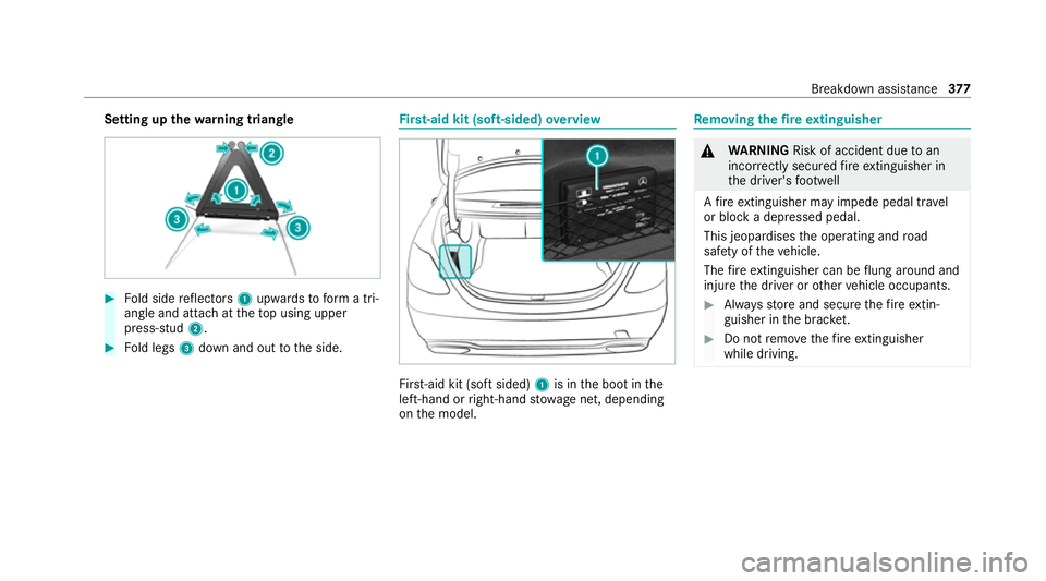
Setting up
thewa rning triangle #
Fold side reflectors 1upwards toform a tri‐
angle and attach at theto p using upper
press-stud 2. #
Fold legs 3down and out tothe side. Fi
rs t-aid kit (soft-sided) overview Fir
st-aid kit (so ftsided) 1is in the boot in the
left-hand or right-hand stowage net, depending
on the model. Re
moving the fire extinguisher &
WARNING Risk of accident due toan
incor rectly secu redfire extinguisher in
th e driver's foot we ll
A fire extinguisher may impede pedal tr avel
or block a depressed pedal.
This jeopardises the operating and road
saf ety of theve hicle.
The fire extinguisher can be flung around and
injure the driver or other vehicle occupants. #
Alw aysst ore and secure thefire extin‐
guisher in the brac ket. #
Do not remo vethefire extinguisher
while driving. Breakdown assi
stance 377
Page 383 of 549
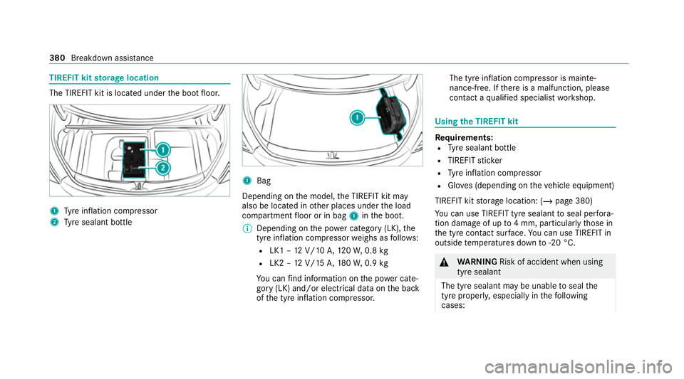
TIREFIT kit
storage location The TIREFIT kit is located under
the boot floor. 1
Tyre inflation compressor
2 Tyre sealant bottle 1
Bag
Depending on the model, the TIREFIT kit may
also be located in other places under the load
compartment floor or in bag 1inthe boot.
% Depending on the po wer category (LK), the
tyre inflation compressor weighs as follo ws:
R LK1 – 12V/10 A,120W, 0.8 kg
R LK2 – 12V/15 A,180W, 0.9 kg
Yo u can find information on the po wer cate‐
gory (LK) and/or electrical data on the back
of the tyre inflation compressor. The tyre inflation compressor is mainte‐
nance-free. If
there is a malfunction, please
conta ct aqualified specialist workshop. Using
the TIREFIT kit Re
quirements:
R Tyre sealant bottle
R TIREFIT sticker
R Tyre inflation compressor
R Gloves (depending on theve hicle equipment)
TIREFIT kit storage location: (/ page 380)
Yo u can use TIREFIT tyre sealant toseal per fora‐
tion dama geof up to4 mm, particular lythose in
th e tyre conta ct surface. You can use TIREFIT in
outside temp eratures down to-20 °C. &
WARNING Risk of accident when using
tyre sealant
The tyre sealant may be unable toseal the
tyre properly, especially in thefo llowing
cases: 380
Breakdown assis tance
Page 399 of 549
amperage,
the electric line could be overloa‐
ded.
This could result in a fire. #
Alw aysre place faulty fuses with speci‐
fi ed new fuses conta iningthe cor rect
amperage. *
NO
TEDama gedue toincor rect fuses Electrical components or sy
stems may be
damaged byincor rect fuses, or their func‐
tionality may be significant lyimpaired. #
Only use fuses that ha vebeen appr oved
by Mercedes-Benz and which ha vethe
cor rect fuse rating. Blown fuses mu
stbe replaced with fuses of the
same rating, which you can recognise bythe col‐
our and the label. The fuse ratings and fu rther
information tobe obser ved can be found in the
fuse assignment diagram.
Fu se assignment diag ram: onthe fuse box in
th e boot (/ page 398). *
NO
TEDama geor malfunctions caused
by moisture Moisture may cause dama
getothe electrical
sy stem or cause it tomalfunction. #
When the fuse box is open, make sure
th at no moisture can enter the fuse
box. #
When closing the fuse box, make sure
th at the seal of the lid is positioned cor‐
re ctly on the fuse box. If
th e newly inser ted fuse also blo ws, ha vethe
cause traced and rectified at a qualified special‐
ist workshop.
Ensure thefo llowing before replacing a fuse:
R The vehicle is secured against rolling away.
R All electrical consumers are switched off.
R The ignition is switched off.
The electrical fuses are located in various fuse
bo xes:
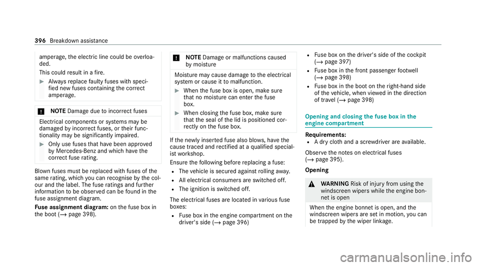
R Fuse box in the engine compartment on the
driver's side (/ page 396) R
Fuse box on the driver's side of the cockpit
(/ page 397)
R Fuse box in the front passenger foot we ll
(/ page 398)
R Fuse box in the boot on theright-hand side
of theve hicle, when vie wed in the direction
of tr avel (/ page 398) Opening and closing
the fuse box in the
engine compa rtment Requ
irements:
R A dry clo thand a sc rewdriver are available.
Obse rveth e no tes on electrical fuses
(/ page 395).
Opening &
WARNING Risk of inju ryfrom using the
windscreen wipers while the engine bon‐
net is open
When the engine bonn etis open, and the
windscreen wipers are set in motion, you can
be trapped bythe wiper linkage. 396
Breakdown assis tance
Page 401 of 549
Opening and closing
the fuse box in the front
passenger foot we ll Obser
vethe no tes on electrical fuses
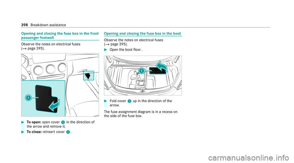
(/ page 395). #
Toopen: open co ver1 inthe direction of
th e ar row and remo veit. #
Toclose: reinse rtco ver1. Opening and closing
the fuse box in the boot Obser
vethe no tes on electrical fuses
(/ page 395). #
Open the boot floor . #
Fold co ver1 up in the direction of the
ar row.
The fuse assignment diagram is in a recess on
th e side of the fuse box. 398
Breakdown assis tance
Page 411 of 549
#
Only inter change the front and rear
wheels if the wheels and tyres ha vethe
same dimensions. Inter
changing the front and rear wheels if the
wheels or tyres ha vediffere nt dimensions can
re nder thege neral operating pe rmit in valid.
The wear pat tern s on the front and rear wheels
dif fer:
R front wheels wear more on the tyre shoulder
R rear wheels wear more in the cent reofthe
tyre
Do not drive wi thtyres that ha vetoo little tread
dep th. This significantly reduces traction on wet
ro ads (aquaplaning).
On vehicles with the same front and rear wheel
size, you can inter change the wheels every
5000 to10,000 km, depending on thewe ar.
Ensure the direction of rotation is maintained for
th e wheels.
Obser vethe instructions and saf ety no tes on
"Changing a wheel" when doing so
(/ page 409). Note
s onstoring wheels When
storing wheels, obser vethefo llowing
no tes:
R Afterre moving wheels, store them in a cool,
dry and preferably dark place.
R Protect the tyres from conta ct withoil,
grease or fuel. Overview of
the ty re-change tool kit *
NO
TEMercedes-AMG vehicles #
Obser vethe no tes in the Supplement.
Yo u could otherwise failto recognise
dangers. Apa
rtfrom some countr y-specific variants, vehi‐
cles are not equipped with a tyre-change tool kit.
Fo r more information on which tyre-changing
to ols are required and appr oved for per form ing a
wheel change on your vehicle, consult a qualified
specialist workshop. Yo
ure qu ire thefo llowing tools, forex ample, to
ch ange a wheel:
R Jack
R Chock
R Wheel wrench
R Cent ring pin
% The jack weighs appr oximately 2.1 kg.
The maximum load capacity of the jack can
be found on thest icke r af fixe dto the jac k.
The jack is maintenance-free. If there is a
malfunction, please conta ct aqualified spe‐
cialist workshop.
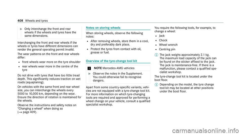
The tyre-change tool kit is located under the
boot floor.
% Depending on the model, the tyre change
to ol kit may be located at other positions
under the boot floor. 408
Wheels and tyres
Page 413 of 549
#
Using wheel spanner 3, turn hub cap1
anti-clockwise and remo veit. #
Tofit: follow the instructions abo vein
re ve rse order.
% Specified tightening torq ue: 25 Nm. Ra
ising theve hicle when changing a wheel Re
quirements:
R There are no persons in theve hicle.
R The vehicle has been prepared for a wheel
ch ange (/ page 409).
R The wheel trims and hub caps ha vebeen
re mo ved (/ page 409).
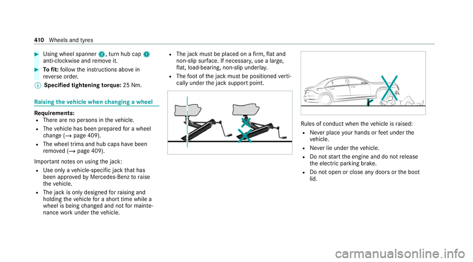
Impor tant no tes on using the jack:
R Use only a vehicle-specific jack that has
been appr oved byMercedes-Benz toraise
th eve hicle.
R The jack is only designed forra ising and
holding theve hicle for a short time while a
wheel is being changed and not for mainte‐
nance workunder theve hicle. R
The jack must be placed on a firm ,fl at and
non-slip sur face. If necessar y,use a lar ge,
fl at, load-bearing, non-slip unde rlay.
R The foot ofthe jack must be positioned verti‐
cally under the jack support point. Ru
les of conduct when theve hicle is raised:
R Never place your hands or feet under the
ve hicle.
R Never lie under theve hicle.
R Do not start the engine and do not release
th e electric parking brake.
R Do not open or close any doors or the boot
lid. 41 0
Wheels and tyres
Page 418 of 549
shop. The new wheel must ha
vethe
cor rect dimensions. %
The emergency spa rewheel is secured in the
emer gency spa rewheel bag in the boot.
Obser vethefo llowing no tes on fitting an emer‐
ge ncy spa rewheel:
R Check the tyre pressure of the emer gency
spa rewheel fitted. Co rrect the pressure as
necessar y.
R The maximum permissible speed with an
emer gency spa rewheel fitted is 80 km/h.
R Do not fit th e emer gency spa rewheel with
sn ow ch ains.
R Replace the emer gency spa rewheel af ter six
ye ars at the latest, rega rdless of wear.
% Ve
hicles with a tyre pressure loss warn‐
ing sy stem: if an emer gency spa rewheel is
fi tted, the tyre pressure loss warning sy stem
cann otfunction reliabl y.Only restart the sys‐
te m again when the emer gency spa rewheel
has been replaced with a new wheel. Ve
hicles with a tyre pressure monitoring
sy stem: if an emer gency spa rewheel is fit‐
te d, the tyre pressure monitoring sy stem
cann otfunction reliabl y.Fo r a few minutes
af te r an emer gency spa rewheel is fitted, the
sy stem may still display the tyre pressure of
th ere mo ved wheel. Only restart the sy stem
again when the emer gency spa rewheel has
been replaced with a new wheel.
Be sure toalso obse rveth efo llowing fur ther
re lated subjects:
R Notes on tyre pressure (/ page 400)
R Tyre pressure table (/ page 401)
R Notes on fitting tyres (/ page 404) Wheels and tyres
415
Page 449 of 549
Display messages
Possible causes/consequences and M
MSolutions #
Neverre lease the bonn etwhen driving. #
Before every trip, ensure that the engine bonn etis loc ked. #
Stop theve hicle immediately in accordance with the traf fic conditions. #
Close the bonn et.
N *T
he boot lid is open. &
DANG ER Risk of exhaust gas poisoning
Combustion engines emit poisonous exhaust gases such as carbon monoxide. Exhaust gases can enter the
ve hicle interior if the boot lid is open when the engine is running, especially if theve hicle is in motion. #
Alw ays switch off the engine before opening the boot lid. #
Never drive with the boot lid open. #
Close the boot lid.
_ Rear left seat backrest not
locked (Example) *T
he seat backrest of the cor responding seat is not engaged. #
Foldthe seat backrest back until it engages. 446
Displaymessa ges and warning/indicator lamps