key MERCEDES-BENZ C-CLASS ESTATE 2007 Repair Manual
[x] Cancel search | Manufacturer: MERCEDES-BENZ, Model Year: 2007, Model line: C-CLASS ESTATE, Model: MERCEDES-BENZ C-CLASS ESTATE 2007Pages: 377, PDF Size: 6.19 MB
Page 179 of 377
Sliding sunroof
176 Panorama sliding sunroof*
Panorama sliding sunroof G
Risk of injury
Make sure that nobody can become trap -
ped when closing the panorama sliding sun-
roof. If danger threatens, release the switc h
and push it briefly in any direction to stop
the panorama sliding sunroof. G
Risk of injury
The glass in the panorama sliding sunroof
could break in an accident. If you are not
wearing a seat belt, there is a risk that yo u
could be thrown through the opening in the
event of the vehicle overturning. Therefore,
always wear a seat belt to reduce the ris k
of injuries.
! Only open the panorama sliding sunroof
if it is free of snow and ice. Otherwise, mal-
functions may occur.
Do not allow anything to protrude from the
panorama sliding sunroof. The seals could
otherwise be damaged.
i When the panorama sliding sunroof is
open, resonance noises may occur as well as the usual airflow noises. They are caused
by minor pressure fluctuations in the vehi-
cle interior. Change the position of the pan-
orama sliding sunroof or open a side
window slightly to reduce or eliminate
these noises.
i It is also possible to open and close the
panorama sliding sunroof from the outsid e
using the "Summer opening" (Y page 111 )
and the "Convenience clos-
ing" (Y page 112) features respectively.
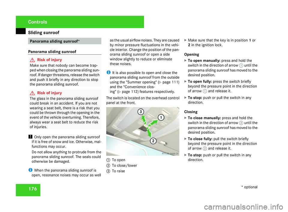
The switch is located on the overhead contro l
panel at the front. 1
To open
2 To close/lower
3 To raise X
Make sure that the key is in position 1or
2 in the ignition lock .
Opening
X To open manually: press and hold the
switch in the direction of arrow 1until th e
panorama sliding sunroof has moved to the
desired position .
X To open fully: press the switch briefl y
beyond the pressure point in the direction
of arrow 1and release it.
X To stop: push or pull the switch in any
direction.
Closin g
X To close manually: press and hold the
switch in the direction of arrow 2until th e
panorama sliding sunroof has moved to the
desired position .
X To close fully: pull the switch briefl y
beyond the pressure point in the direction
of arrow 2and release it.
X To stop: push or pull the switch in any
direction. Controls
* optional
204_AKB; 2; 3, en-G
B
mkalafa , 2007-06-26T23:11:51+02:00 - Seite 176
Page 180 of 377
Sliding sunroof
177
Closing with increased force and without
the anti-entrapment function G
Risk of injury
Make sure that nobody can become trap -
ped and a serious or even fatal injury is not
caused as you close the panorama sliding
sunroof with increased force or without the
anti-entrapment function .
If the panorama sliding sunroof locks up dur-
ing closing:
X Immediately after it locks up, pull the
switch again to the pressure point in the
direction of arrow 2until the panoram a
sliding sunroof is closed.
The panorama sliding sunroof is closed
with more force.
If the panorama sliding sunroof locks up dur-
ing closing again:
X Immediately after it locks up, pull the
switch again to the pressure point in the
direction of arrow 2until the panoram a
sliding sunroof is closed.
The panorama sliding sunroof is closed
without the anti-entrapment function. Raisin
g
The panorama sliding sunroof can be raised
at the rear for ventilation.
X To raise manually: press and hold the
switch in the direction of arrow 3until th e
panorama sliding sunroof has moved to the
desired position .
X To raise fully: briefly press the switch
beyond the pressure point in the direction
of arrow 3and release it.
X To stop: push or pull the switch in any
direction.
Lowering and closin g
X To lower manually: press and hold the
switch in the direction of arrow 2until th e
panorama sliding sunroof has moved to the
desired position .
X To lower fully: briefly pull the switch
beyond the pressure point in the direction
of arrow 2and release it.
X To stop: push or pull the switch in any
direction. Roller sunblinds The roller sunblinds provide protection from
the sun. The two roller sunblinds can only be
opened and closed together when the pano-
rama sliding sunroof is closed . G
Risk of injury
Make sure that nobody can become trap -
ped as you open or close the roller sun-
blinds.
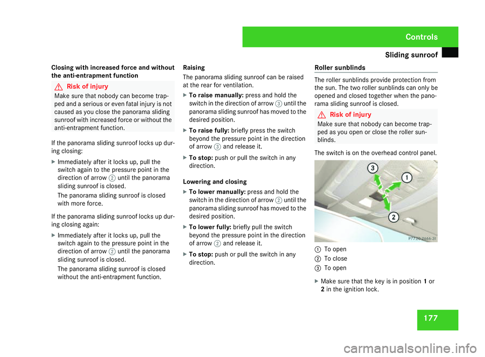
The switch is on the overhead control panel. 1
To open
2 To close
3 To open
X Make sure that the key is in position 1or
2 in the ignition lock . Cont
rols
204_AKB; 2; 3, en-GB
mkalafa,
2007-06-26T23:11:51+02:00 - Seite 177
Page 181 of 377
Sliding sunroof
178
Opening
X
To open manually: press the switch in the
direction of arrow 1or3 until the roller
sunblinds have moved to the desired posi -
tion.
X To open fully :briefly press the switc h
beyond the pressure point in the direction
of arrow 1or3 .
X To stop: push or pull the switch in any
direction.
Closin g
X To close manually: pull the switch in the
direction of arrow 2or until the roller sun-
blinds have moved to the desired position.
X To close fully :briefly pull the switc h
beyond the pressure point in the direction
of arrow 2.
X To stop: push or pull the switch in any
direction.
Rain-closing feature *When the key is in position
0in the ignition
lock or is removed, the panorama sliding sun-
roof closes automatically: R
if it starts to rain
R at extreme outside temperatures
R after 6 hour s
R if there is a malfunction in the power supply
The panorama sliding sunroof remains raised
at the rear in order to allow ventilation of the
vehicle interior .
i The panorama sliding sunroof does not
close if:
R it is raised at the rear
R it is blocked
R no rain is falling within the field of the rain
sensor in the windscreen (e.g. because
the vehicle is under a bridge or in a car -
port )
Resetting the panorama sliding sunroo f
and the roller sunblinds Reset the panorama sliding sunroof and the
roller sunblinds if the panorama sliding sun-
roof or the roller sunblinds do not ope
n
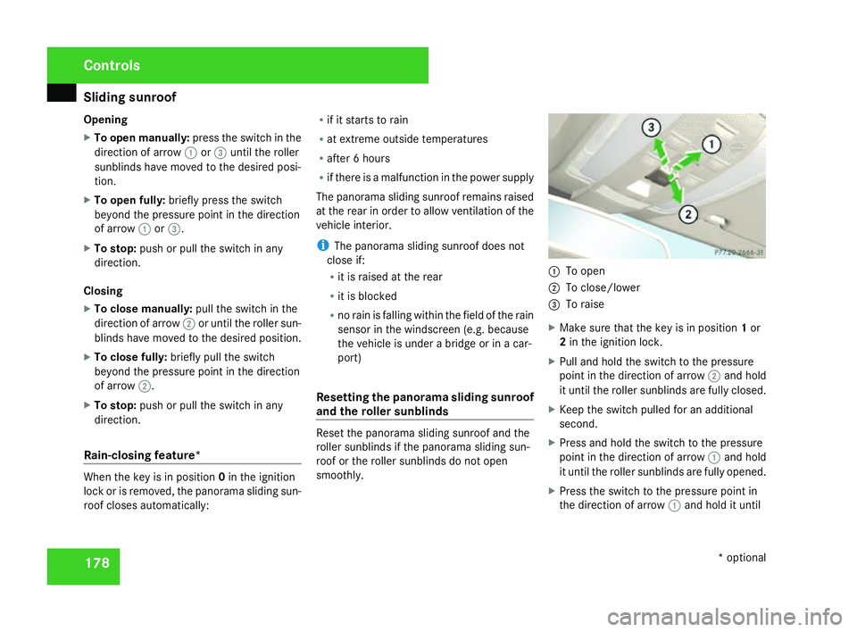
smoothly. 1
To open
2 To close/lower
3 To raise
X Make sure that the key is in position 1or
2 in the ignition lock .
X Pull and hold the switch to the pressure
point in the direction of arrow 2and hold
it until the roller sunblinds are fully closed.
X Keep the switch pulled for an additional
second.
X Press and hold the switch to the pressure
point in the direction of arrow 1and hold
it until the roller sunblinds are fully opened.
X Press the switch to the pressure point in
the direction of arrow 1and hold it until Control
s
* optional
204_AKB; 2; 3, en-GB
mkalafa,
2007-06-26T23:11:51+02:00 - Seite 178
Page 197 of 377
Loading and stowing
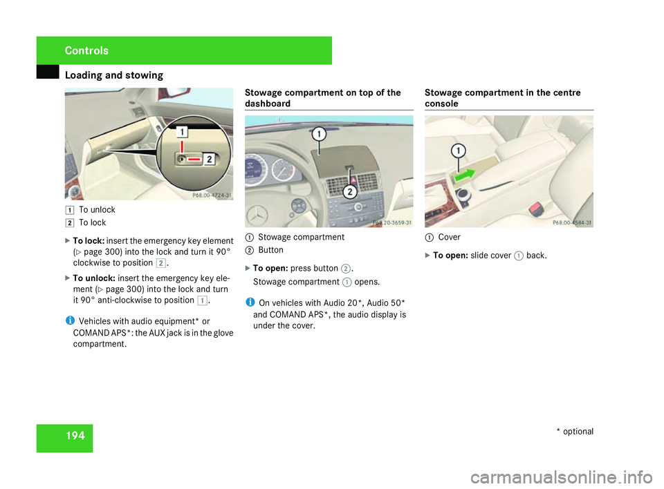
194$
To unlock
% To lock
X To lock :insert the emergency key elemen t
( Y page 300) into the lock and turn it 90°
clockwise to position %.
X To unlock: insert the emergency key ele-
ment (Y page 300) into the lock and turn
it 90° anti-clockwise to position $.
i Vehicles with audio equipment* or
COMAND APS*: the AUX jack is in the glove
compartment. Stowage compartment on top of the
dashboard
1
Stowage compartment
2 Button
X To open: press button 2.
Stowage compartment 1opens.
i On vehicles with Audio 20*, Audio 50*
and COMAND APS*, the audio display is
under the cover. Stowage compartment in the centre
console 1
Cove r
X To open: slide cover 1back. Controls
* optional
204_AKB; 2; 3, en-GB
mkalafa,
2007-06-26T23:11:51+02:00 - Seite 194
Page 200 of 377
Features
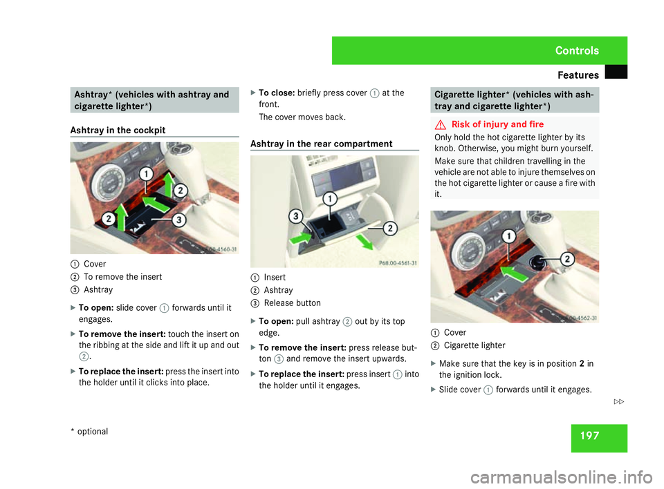
197Ashtray* (vehicles with ashtray and
cigarette lighter*)
Ashtray in the cockpit 1
Cove r
2 To remove the insert
3 Ashtray
X To open: slide cover 1forwards until it
engages.
X To remove the insert: touch the insert on
the ribbing at the side and lift it up and ou t
2 .
X To replace the insert: press the insert into
the holder until it clicks into place .X
To close: briefly press cover 1at th e
front.
The cover moves back.
Ashtray in the rear compartment 1
Insert
2 Ashtray
3 Release butto n
X To open: pull ashtray 2out by its top
edge.
X To remove the insert: press release but-
ton 3and remove the insert upwards .
X To replace the insert: press insert1into
the holder until it engages . Cigarette lighter* (vehicles with ash
-
tray and cigarette lighter*) G
Risk of injury and fire
Only hold the hot cigarette lighter by its
knob. Otherwise, you might burn yourself.
Make sure that children travelling in the
vehicle are not able to injure themselves on
the hot cigarette lighter or cause a fire with
it. 1
Cove r
2 Cigarette lighter
X Make sure that the key is in position 2in
the ignition lock .
X Slide cover 1forwards until it engages. Controls
* optional
204_AKB; 2; 3, en-GB
mkalafa,
2007-06-26T23:11:51+02:00 - Seite 197 Z
Page 203 of 377
Features
200
X
Remove the cover of the aerial plug from
the back of the mobile phone and stow it in
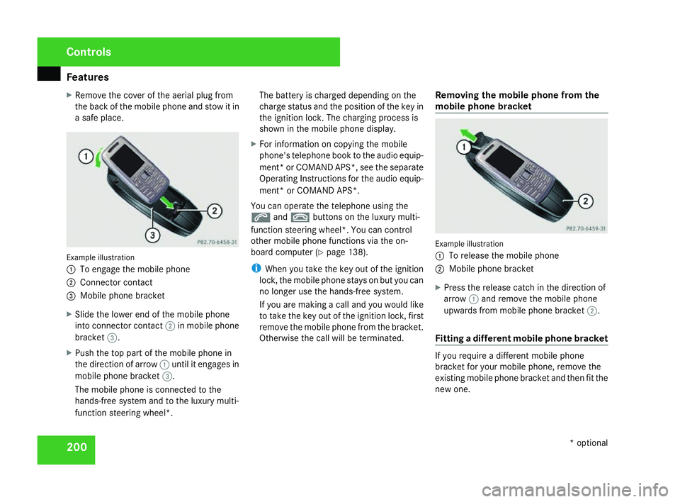
a safe place. Example illustration
1
To engage the mobile phone
2 Connector contact
3 Mobile phone bracket
X Slide the lower end of the mobile phone
into connector contact 2in mobile phon e
bracket 3.
X Push the top part of the mobile phone in
the direction of arrow 1until it engages in
mobile phone bracket 3.
The mobile phone is connected to the
hands-free system and to the luxury multi-
function steering wheel*. The battery is charged depending on the
charge status and the position of the key in
the ignition lock. The charging process is
shown in the mobile phone display
.
X For information on copying the mobil e
phone's telephone book to the audio equip-
ment *or COMAND APS*, see the separate
Operating Instructions for the audio equip-
ment* or COMAND APS* .
You can operate the telephone using the
s andt buttons on the luxury multi-
function steering wheel*. You can contro l
other mobile phone functions via the on-
board computer (Y page 138).
i When you take the key out of the ignition
lock, the mobile phone stays on but you can
no longer use the hands-free system.
If you are making a call and you would like
to take the key out of the ignition lock, first
remove the mobile phone from the bracket .
Otherwise the call will be terminated. Removing the mobile phone from the
mobile phone bracket Example illustration
1
To release the mobile phone
2 Mobile phone bracket
X Press the release catch in the direction of
arrow 1and remove the mobile phon e
upwards from mobile phone bracket 2.
Fitting a different mobile phone bracket If you require a different mobile phon
e
bracket for your mobile phone, remove the
existing mobile phone bracket and then fit the
new one. Controls
* optional
204_AKB; 2; 3, en-GB
mkalafa,
2007-06-26T23:11:51+02:00 - Seite 200
Page 207 of 377
Refuelling
20
4 The first 1,500 km
If you treat the engine with sufficient car e
from the very start, it will reward you with
excellent performance for a very long period
afterwards .
R You should therefore drive at varying road
and engine speeds for the first 1,500 km.
R Avoid heavy loads, e.g. driving at full throt-
tle, during this time. Do not exceed 2
/ 3 of
the maximum permissible engine speed for
each gear.
R Change gear in good time.
R Do not shift down a gear manually in order
to brake.
Vehicles with automatic transmission* :
R Try to avoid depressing the accelerator
pedal beyond the pressure point (kick -
down).
R Only use ranges 3,2 or 1for slow driving,
e.g. in mountainous terrain. Refuellin
g Refuelling
G
Risk of explosion
Fuel is highly flammable. Fire, naked flames
and smoking are therefore prohibited when
handling fuels.
Switch off the engine before refuelling. G
Risk of injury
Avoid any contact with fuels.
You can damage your health if your skin
comes into direct contact with fuel or if yo u
inhale the vapour. G
Risk of fire
Do not use petrol to refuel vehicles with a
diesel engine. Never mix diesel with petrol.
This would damage the fuel system and
engine and could result in a vehicle fire.
! Do not use petrol to refuel vehicles with a
diesel engine. Do not use diesel to refuel
vehicles with a petrol engine. Never mix
diesel with petrol. Even small amounts of
the wrong fuel will damage the injection
system. Damage resulting from adding the
wrong fuel is not covered by the warranty. !
Do not start the engine if you accidentally
refuelled with the wrong fuel. Otherwise
you risk engine damage. Have the fuel sys-
tem emptied completely.
When you open or close the vehicle with the
key or KEYLESS GO*, the fuel filler flap is
automatically unlocked or locked.
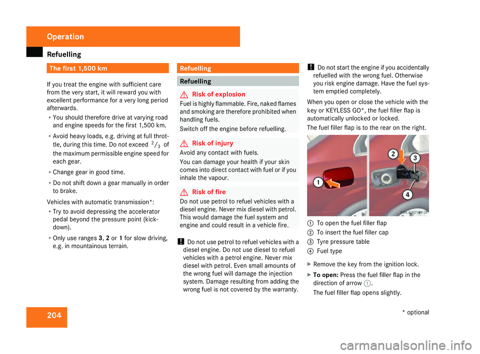
The fuel filler flap is to the rear on the right . 1
To open the fuel filler flap
2 To insert the fuel filler cap
3 Tyre pressure table
4 Fuel typ e
X Remove the key from the ignition lock.
X To open: Press the fuel filler flap in the
direction of arrow 1.
The fuel filler flap opens slightly. Operation
* optional
204_AKB; 2; 3, en-GB
mkalafa,
2007-06-26T23:11:51+02:00 - Seite 204
Page 209 of 377
Engine compartment
206R
Vegetable oil
R Petrol
R Petroleum
R Kerosene
Do not add such fuels to diesel fuel and do
not use any special additives (exception:
flow improvers – see "Low outside temper-
atures").
Damage caused by the use of unapproved
fuels or additives is not covered by the war-
ranty.
Low outside temperatures The flow properties of diesel may be insuffi-
cient at low ambient temperatures.
To prevent operating problems, diesel fuel
with improved cold flow qualities is available
during the winter months. Your vehicle must
be refuelled with this winter diesel at temper-
atures of -5 °C or below.
You can use this winter diesel at tempera-
tures down to about -20 °C without problems.
If only summer diesel fuel or less cold-resist-
ant winter diesel fuel (e.g. in Mediterranean
regions) is available, you should add an
amount of flow improver to the fuel corre-
sponding to the outside temperature. Mix the additive with the diesel in good time,
before the flow properties of the diesel
become insufficient. Otherwise, malfunctions
can only be rectified by heating the entire fuel
system, e.g. by parking the vehicle in a heated
garage. G
Risk of fire
Do not use petrol to refuel vehicles with a
diesel engine. Never mix diesel with petrol.
This would damage the fuel system and
engine and could result in a vehicle fire.
Flow improver
The effectiveness of a flow improver is not
guaranteed with every fuel. Observe the infor -
mation provided by the manufacturer when
using a flow improver. Only use flow improv-
ers that have been tested and approved by
Mercedes-Benz. Information about flow
improvers that have been tested and
approved by Mercedes-Benz can be obtained
from any Mercedes-Benz Service Centre. Engine compartment
Bonne
t G
Risk of accident
Do not pull the release lever while the vehi-
cle is in motion. The bonnet could other-
wise open.
Opening G
Risk of injury
There is a risk of injury if the bonnet is open,
even if the engine is not running.
Some engine components can become
very hot.
To avoid the risk of burns, only touch thos e
components described in the Owner’s Man-
ual and observe the relevant safety notes. G
Risk of injury
The radiator fan between the radiator and
the engine can start automatically, even if
the key has been removed from the ignition
lock. For this reason you must not reach
into the turning area of the fan. You could
otherwise sustain an injury.
Vehicles with a petrol engine: Operatio
n
204_AKB; 2; 3, en-GB
mkalafa,
2007-06-26T23:11:51+02:00 - Seite 206
Page 210 of 377
Engine compartment
207The electronic ignition system uses high
voltage. For this reason you must never
touch components of the ignition system
(ignition coil, ignition cable, spark plug con-
nector, test socket) when :
R the engine is running
R the engine is being started
R the ignition is switched on and the engine
is being cranked by hand
Vehicles with a diesel engine :
The electronic injection control uses high
voltage. Therefore, never touch fuel injec -
tion system components when:
R the engine is running
R the engine is being started
R the ignition is switched on
X Make sure that the windscreen wipers are
switched off. G
Risk of injury
The windscreen wipers and wiper rod s
could be set in motion.
When the bonnet is open, you or others
could be injured by the wiper rods. Make sure that the windscreen wipers are
switched off and that the key has bee
n
pulled out of the ignition lock before open-
ing the bonnet.
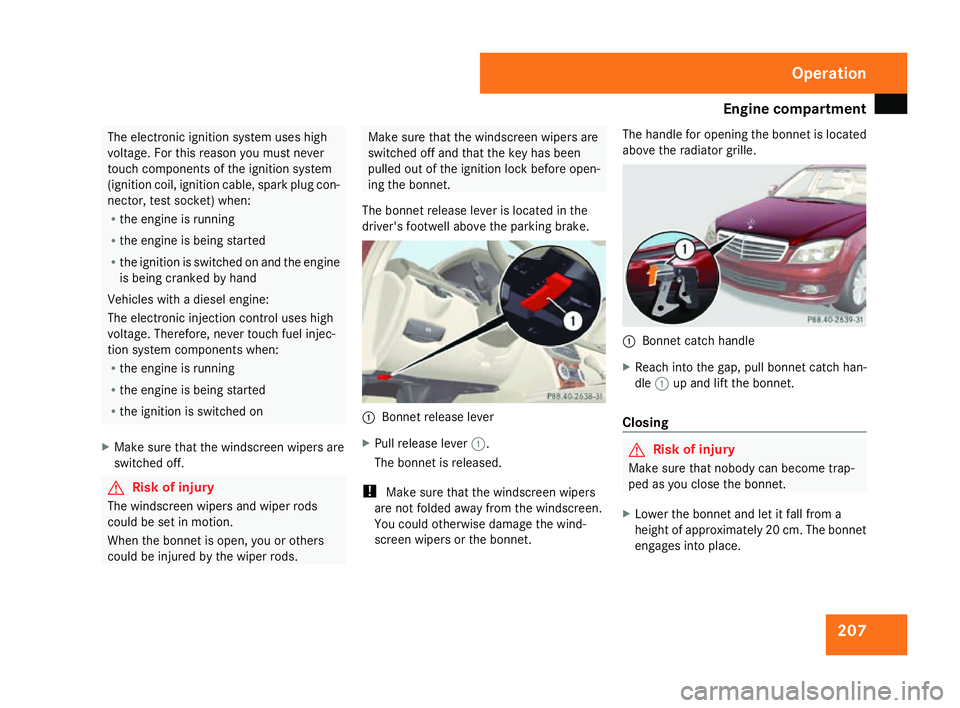
The bonnet release lever is located in the
driver's footwell above the parking brake. 1
Bonnet release lever
X Pull release lever 1.
The bonnet is released.
! Make sure that the windscreen wipers
are not folded away from the windscreen .
You could otherwise damage the wind-
screen wipers or the bonnet. The handle for opening the bonnet is located
above the radiator grille.
1
Bonnet catch handle
X Reach into the gap, pull bonnet catch han -
dle 1up and lift the bonnet.
Closing G
Risk of injury
Make sure that nobody can become trap -
ped as you close the bonnet.
X Lower the bonnet and let it fall from a
height of approximately 20 cm. The bonnet
engages into place. Operation
204_AKB; 2; 3, en-GB
mkalafa,
2007-06-26T23:11:51+02:00 - Seite 207
Page 217 of 377
Tyres and wheels
21
4 Tyre pressure loss warning system
G
Risk of accident
The tyre pressure loss warning system*
does not warn you of an incorrectly set tyre
pressure. The table on the inside of the fue l
filler flap will help you decide whether the
tyre pressures should be corrected.
The tyre pressure loss warning system*
does not replace the need to regularly
check your vehicle's tyre pressures, since
an even loss of pressure on several tyres at
the same time cannot be detected by the
tyre pressure loss warning system*.
The tyre pressure loss warning system* is
not able to warn you of a sudden loss of
pressure, e.g. following penetration by a
foreign object.
In the event of a sudden loss of pressure,
bring the vehicle to a halt by braking care-
fully. Do not make any sudden steering
movements when doing so.
While the vehicle is in motion, the tyre pres-
sure loss warning system* monitors the set
tyre pressure using the rotational speed of
the wheels. This enables the system to detect
significant pressure loss in a tyre. If the spee d
of rotation of a wheel changes as a result of a loss of pressure, a corresponding warning
message will appear in the multi-function dis-
play.
The function of the tyre pressure loss warning
system* is limited or delayed if:
R
snow chains are fitted to your vehicle's
tyres
R road conditions are wintry
R you are driving on sand or grave l
R you adopt a very sporty driving style (cor -
nering at high speeds or driving with high
rates of acceleration)
R you are towing a very heavy or large trailer
R you are driving with a heavy load (in th e
vehicle or on the roof)
Restarting the tyre pressure loss warn-
ing system* Restart the tyre pressure loss warning sys-
tem* if you have
:
R changed the tyre pressure
R changed the wheels or tyre s
R fitted new wheels or tyres
X Before restarting, consult the table of tyre
pressures on the inside of the fuel filler fla pto ensure that the tyre pressure in all fou
r
tyres is set correctly for the operating con-
ditions concerned .
X Also observe the notes in the section on
tyre pressures (Y page 213). G
Risk of accident
The tyre pressure loss warning system* can
only give reliable warnings if you have set
the correct tyre pressure.
If an incorrect tyre pressure is set, thes e
incorrect values will be monitored.
A tyre with insufficient pressure results in
an instability of the vehicle when driving,
thus increasing the risk of an accident .
Configuring with the multi-function steer-
ing wheel
X Make sure that the key is in position 2in
the ignition lock .
X Press èto select Tyre pressure
menu: R.
X Press the íbutton.
The following appears in the multi-function
display: RFI active Reactivate: ROperation
* optional
204_AKB; 2; 3, en-GB
mkalafa,
2007-06-26T23:11:51+02:00 - Seite 214