air condition MERCEDES-BENZ C-CLASS ESTATE 2018 Owners Manual
[x] Cancel search | Manufacturer: MERCEDES-BENZ, Model Year: 2018, Model line: C-CLASS ESTATE, Model: MERCEDES-BENZ C-CLASS ESTATE 2018Pages: 609, PDF Size: 11.38 MB
Page 23 of 609
back conditions, please visit
the national
Mercedes-Benz website foryo ur count ry. Mercedes-Benz Genuine
Parts
000F ENVIRONMENTAL
NOTEEnvironmental
dama gecaused bynot using recycled
re conditioned components Daimler
AGoffers recycled reconditioned
components and pa rts with the same quality
as new parts. The same entitlement from the
implied warranty is valid as for new parts. 0007
Use recycled reconditioned compo‐
nents and pa rts from Daimler AG. 000E
NO
TEImpairment of the operating ef fi‐
ciency of there stra int sy stems from
ins talling accessory parts or from repairs
or we lding Airbags and seat belt
tensioners, as well as
control units and sensors forth ere stra int
sy stems, may be ins talled in thefo llowing
areas of your vehicle:
R doors
R door pillars
R door sills
R seats
R cockpit
R instrument clus ter
R centre console
R late ra lro of frame 0007
Do not ins tall accessory parts such as
audio sy stems in these areas. 0007
Do not car ryout repairs or welding. 0007
Have accesso ries retrofitted at a quali‐
fi ed specialist workshop. Yo
u could jeopardise the operating saf ety of your
ve hicle if you use parts, tyres and wheels as well
as accessories releva nt tosaf ety which ha venot
been appr ovedby Mercedes-Benz. Saf ety-re le‐
va nt sy stems, e.g. the brake sy stem, may mal‐
function. Only use Mercedes-Benz Genuine Parts
or parts of equal qualit y.Only use tyres, wheels
and accessories that ha vebeen specifically
appr ovedfo ryo ur vehicle model.
Mercedes-Benz tests original parts and con ver‐
sion parts and accessories that ha vebeen spe‐
cifically appr ovedfo ryo ur vehicle model forth eir
re liability, saf ety and suitabilit y.Despite ongoing
ma rket resear ch, Mercedes-Benz is unable to
assess other parts. Mercedes-Benz therefore
accepts no responsibility forth e use of such
parts in Mercedes-Benz vehicles, even if they
ha ve been of ficially appr oved or independently
appr ovedby ate sting centre.
Cer tain parts are only of ficially appr ovedfor
ins tallation or modification if they comply wi th
legal requirements. All Mercedes-Benz Genuine
Pa rts meet the appr oval requ irements. The use
of non-appr oved parts may in validate theve hi‐
cle's general operating pe rmit. 20
General no tes
Page 25 of 609
Obser
vethe "On-board electronics" section in
"Technical data". 000A
WARNING Risk offire due toflammable
materials on hot parts of theex haust
sy stem
Flammable material such as lea ves, grass or
twigs may ignite if they come into contact
wi th hot parts of theex haust sy stem. 0007
When driving on unpa vedro ads or off-
ro ad, regular lych eck theve hicle under‐
side. 0007
Remo vetrapped plants or other flam‐
mable material, in particular. 0007
Ifth ere is damage, consult a qualified
specialist workshop immediately. 000E
NO
TEDama getotheve hicle In
thefo llowing situations, in particular, there
is a risk of damage totheve hicle:
R theve hicle becomes grounded, e.g. on a
high kerb or an unpa vedro ad R
theve hicle is driven toofast over an
obs tacle, e.g. a kerb, speed bump or pot‐
hole
R a heavy object strike sth e underbody or
ch assis components
In situations such as this, the body, the
underbody, chassis components, wheels or
tyres could be damaged without the damage
being visible. Components damaged in this
wa y can unexpec tedly fail or, in the case of
an accident, may not absorb the loads that
arise as intended.
If th e underbody panelling is damaged, flam‐
mable materials such as lea ves, grass or
twigs can collect between the underbody and
th e underbody panelling. These materials
may ignite if they come into contact wi thhot
parts on theex haust sy stem. 0007
Have theve hicle checked and repaired
immediately at a qualified specialist
wo rkshop.
or 0007
If driving saf ety is impaired while con‐
tinuing your journe y,pull over and stop
th eve hicle immediately in accordance
with the traf fic conditions, and contact
a qu alified specialist workshop. Ve
hicles with a 48 V on-board electrical sys‐
te m (EQ Boo sttech nology) 000A
DANG ER Risk of fata l injury bytouching
damaged high-voltage co mponents
Ve hicles with a 48 V on-board electrical sys‐
te m contain individual high-voltage compo‐
nents. These high-voltage components are
under high voltage.
If yo u modify co mponent parts of these high-
vo ltage components or touch damaged com‐
ponent parts, you may be electrocuted.
High voltage components may be damaged
in an accident, although the damage may not
be visible. 0007
Never per form modifications tocompo‐
nent pa rts of high-voltage components. 22
General no tes
Page 27 of 609
C) A 639 580 02
18
Ye ar of manufacture: 20 15
Fu lfils all releva nt conditions
Directi veNo. 2006/42/EC
b)
Desc ript ion and purpose of use:
The jack is only intended forra ising the specified
ve hicle in accordance with the operating instruc‐
tions af fixe dto the jac k.
3.
Refe rence da taofthe harmonised standards or
specifications
A) ISO 4063, EN ISO 14341- A,DBL 7382.20,
MBN 10435, AS 2693
B) ISO 4063, ISO 14341- A,DBL 7392. 10, MBN
10 435
C) DBL 7392. 10, DBL 8230. 10
The tech nical documentation of the product is
st ored at the manufacturer's plant. Representa‐
tive forth e compilation of thete ch nical docu‐
mentation: Director of theTe ch nical Department
Brano a.s. 4.
Hradec nad Mor
avicí
City
5.
05.05.20 15
Date
Signed by
Director of Quality TIREFIT kit
Co
py and translation of the original declaration
of confo rmity:
EC declaration of conformity
In accordance with EC Directive 2006/42/EC
We hereby declare that the product
Product designation: Daimler electric air pump
Model designation: 0851ve, DT/UW 200046
MB pa rtno.: A 000 583 8200
complies wi th thefo llowing releva nt regulations:
2004/108/EC Applied harmonised
standards, in particular:
DIN EN 55 014-1
DIN EN 550 14-2:2009-06
Manufactu rer: Dunlop Tech GmbH
Ad dress: Bir kenhaine rstrasse 77, 63450 Hanau,
Germany
Auth orised representative: IMS dept.
Date: June 20 15
Signatu re: IMS-AM, IMS-AE-L Diagnostics connection
The diagnostics connection is only intended for
th e connection of diagnostic devices at a quali‐
fi ed specialist workshop. 000A
WARNING Risk of accident due tocon‐
necting devices tothe diagnostics con‐
nection
If yo u connect equipment toa diagnostics
connection in theve hicle, it may af fect the
operation of vehicle sy stems. 24
General no tes
Page 30 of 609
of an accident,
rescue services can use the QR
code toquickly find the appropriate rescue card
fo ryo ur vehicle. The cur rent rescue card con‐
ta ins the most impor tant information about your
ve hicle in a compact form , e.g. thero uting of the
electric lines.
Fu rther information can be obtained at http://
www.mercedes-benz.de/qr-code. Data
storage Electronic control units
Elect
ronic control units are fitted in your vehicle.
Some of these are necessary forth e safe opera‐
tion of your vehicle, while some assist you when
driving (driver assis tance sy stems). In addition,
yo ur vehicle pr ovides com fort and enter tainment
functions, which are also made possible byelec‐
tronic control units.
Elect ronic control units contain da tamemories
which can temp orarily or permanently store
te ch nical information about theve hicle's operat‐
ing state, component loads, main tenance
re qu irements and tech nical events or faults. In
general, this information documents thest ate
of a component part, a module, a sy stem or the
sur roundings such as:
R operating status of sy stem components (e.g.
fi ll le vels, battery status, tyre pressure)
R status messages concerning theve hicle or
its individual components (e.g. number of
wheel revo lutions/speed, longitudinal accel‐
eration, lateral acceleration, display of fas‐
te ned seat belts)
R malfunctions or faults in impor tant sy stem
components (e.g. lights, brakes)
R information on events leading tovehicle
damage
R system reactions in special driving situations
(e.g. airbag deployment, inter vention of sta‐
bility control sy stems)
R ambient conditions (e.g. temp erature, rain
sensor)
In addition toprov iding the actual control unit
function, this data assists the manufacturer in
de tecting and rectifying faults and optimising
ve hicle functions. The majority of this data is te
mp orary and is only processed in theve hicle
itself. Only a small portion of the data is stored
in theeve nt or fault memor y.
When your vehicle is serviced, tech nical da ta
from theve hicle can be read out byservice net‐
wo rkemplo yees (e.g. workshops, manufactur‐
ers) or third parties (e.g. breakdown services).
Services include repair services, maintenance
processes, warranty claims and quality assur‐
ance measures, forex ample. The read out is per‐
fo rm ed via the legally prescribed port forthe
diagnostics connection in theve hicle. The
re spective service network locations or third
parties collect, process and use the data. They
document tech nical statuses of theve hicle,
assist in finding faults and impr oving quality and
are transmitted tothe manufacturer, if neces‐
sar y.Fu rthermore, the manufacturer is subject
to product liability. Forth is, the manufacturer
requ irestech nical da tafrom vehicles.
Fa ult memories in theve hicle can be reset by a
service outlet as part of repair or maintenance
wo rk. Gene
ral no tes 27
Page 35 of 609
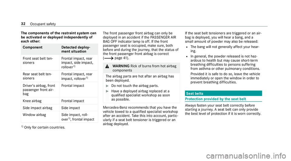
The co
mponents of there stra int sy stem can
be activated or deplo yed independently of
each other: Component De
tected deploy‐
ment situation
Fr ont seat belt ten‐
sioners Fr
ontal impact, rear
impact, side impact,
ro llo ver 1) Re
ar seat belt ten‐
sioners Fr
ontal impact, rear
impact, rollo ver 1) Driver's airbag, front
passenger front air‐
bag
Fr
ontal impact Knee airbag
Frontal impact Side impact airbag Side impact
Wi ndow airba gS ide impact,roll‐
over 1)
, frontal impact 1)
Only for cer tain countries. The front passen
ger front airbag can only be
depl oyed in an accident if thePA SSENGER AIR
BA G OFF indicator lamp is off. If the front
passenger seat is occupied, make sure, bo th
before and during the journe y,that thest atus of
th e front passenger front airbag is cor rect
(0013 page 41). 000A
WARNING Rick of burns from hot airbag
components
The airbag parts are hot af ter an airbag has
been depl oyed. 0007
Do not touch the airbag parts. 0007
Have a deplo yed airbag replaced at a
qu alified specialist workshop as soon
as possible. Mercedes-Benz
recommends that you ha vethe
ve hicle towe dto aqu alified specialist workshop
af te r an accident. Take this into account, partic‐
ularly if a seat belt tensioner is trig gered or an
airbag deplo yed. If
th e seat belt tensioners are trig gered or an air‐
bag is deplo yed, you will hear a bang, and a
small amount of powder may also be released:
R The bang will not generally af fect your hear‐
ing.
R Ingeneral, the powder released is not haz‐
ardous tohealth but may cause short-term
breathing dif ficulties topersons suf fering
from as thma or other pulmonary conditions.
Pr ov ided it is safe todo so, lea vetheve hicle
immediately or open the window in order to
pr eve nt brea thing dif ficulties. Seat belts
Pr
otection pr ovided bythe seat belt Alw
aysfast enyour seat belt co rrectly before
st arting a journe y.A seat belt can only pr ovide
th e best le vel of pr otection if it is worncor rectly. 32
Occupant saf ety
Page 160 of 609
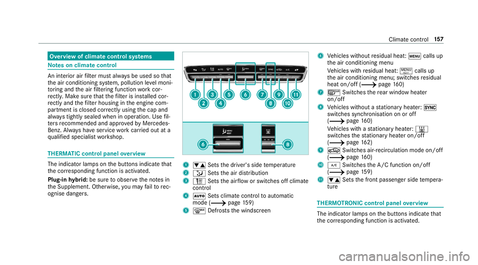
Overview of climate control sy
stems Note
s on climate control An interior air
filter must alw ays be used so that
th e air conditioning sy stem, pollution le vel moni‐
to ring and the air filtering function workcor‐
re ctly. Ma kesure that thefilter is ins talled cor‐
re ctly and thefilter housing in the engine com‐
partment is closed cor rectly using the cap and
alw ays tightly sealed when in operation. Use fil‐
te rs recommended and appr ovedby Mercedes-
Benz. Alw ays ha veservice workcar ried out at a
qu alified specialist workshop. THERMATIC control panel
overview The indicator lamps on
the buttons indicate that
th e cor responding function is activated.
Plug-in hybrid: be sure toobser vethe no tes in
th e Supplement. Otherwise, you may failto rec‐
ognise dangers. 1
0082 Setsthe driver's side temp erature
2 008F Setsthe air distribution
3 002D Setsthe air flow or switches off climate
control
4 0058 Sets climate control toautomatic
mode (0013 page159)
5 0064 Defrosts the windscreen 6
Vehicles without residual heat: 008Acalls up
th e air conditioning menu
Ve hicles with residual heat: 0006calls up
th e air conditioning menu; switches residual
heat on/off (0013 page160)
7 006C Switches there ar wind owheater
on/off
8 Vehicles without a stationary heater: 0015
swit ches synchronisation on or off
(0013 page160)
Ve hicles with a stationary heater: 003B
swit ches thest ationary heater on/off
(0013 page162)
9 0072 Switches ai r-re circulation mode on/off
(0013 page 160)
A 005A Switches the A/C function on/off
(0013 page159)
B 0082 Setsthe front passenger side temp era‐
ture THERMOTRONIC control panel
overview The indicator lamps on
the buttons indicate that
th e cor responding function is activated. Climate
control 157
Page 161 of 609
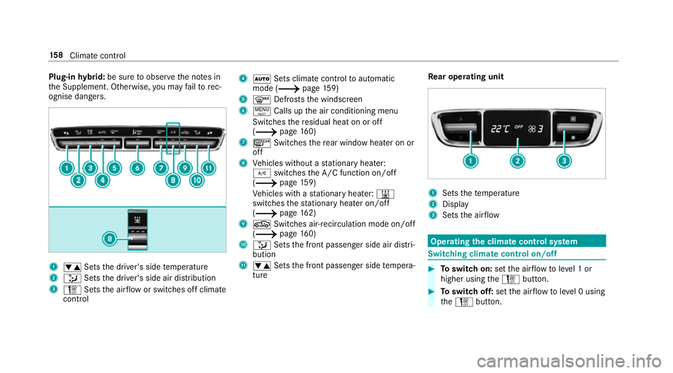
Plug-in
hybrid: be sure toobser vethe no tes in
th e Supplement. Otherwise, you may failto rec‐
ognise dangers. 1
0082 Setsthe driver's side temp erature
2 008F Setsthe driver's side air distribution
3 002D Setsthe air flow or switches off climate
control 4
0058 Sets climate control toautomatic
mode (0013 page159)
5 0064 Defrosts the windscreen
6 0006 Calls up the air conditioning menu
Switches there sidual heat on or off
(0013 page160)
7 006C Switches there ar wind owheater on or
off
8 Vehicles without a stationary heater:
005A switches the A/C function on/off
(0013 page159)
Ve hicles with a stationary heater: 003B
swit ches thest ationary heater on/off
(0013 page162)
9 0072 Switches ai r-re circulation mode on/off
(0013 page 160)
A 008F Setsthe front passenger side air distri‐
bution
B 0082 Setsthe front passenger side temp era‐
ture Re
ar operating unit 1
Sets thete mp erature
2 Display
3 Sets the air flow Operating
the clima tecont rol sy stem Switching clima
tecont rol on/off 0007
Toswitch on: setthe air flow toleve l 1 or
higher using the002D button. 0007
Toswitch off: setthe air flow toleve l 0 using
th e002D button. 15 8
Climate cont rol
Page 174 of 609
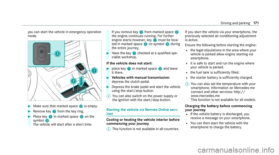
yo
u can start theve hicle in emer gency operation
mode. 0007
Makesure that mar ked space 2is em pty. 0007
Remo vekey1 from theke yring. 0007
Place key1 in mar ked space 2onthe
symbol 3.
The vehicle will start af ter a short time. If
yo ure mo vekey1 from mar ked space 2
th e engine continues running. For fur ther
engine starts ho wever,ke y1 must be loca‐
te d in mar ked space 2on symbol 3during
th e entire journe y. 0007
Have theke y1 checked at a qualified spe‐
cialist workshop.
If th eve hicle does not star t: 0007
place key1 in mar ked space 2and lea ve
it th ere. 0007
Vehicles with manual transmission:
depress the clutch pedal. 0007
Depress the brake pedal and start theve hicle
using thest art/ stop button.
0009 You can also swit chon the po wer supp lyor
th e ignition with thest art/ stop button. St
arting theve hicle via Remo teOnline serv‐
ices Cooling or heating
theve hicle interior before
commencing your journey
0009 This function is not available in all countries. If
yo ustart theve hicle via your smartphone, the
pr ev iously selec ted air conditioning adjustment
is active.
Ensure thefo llowing before starting the engine:
R the legal stipulations in the area where your
ve hicle is par ked allow engine starting via
smartphone.
R it is safe tostart and runth e engine where
yo ur vehicle is par ked.
R the fuel tank is su fficiently filled.
R thest ar ter battery is suf ficiently charge d.
0009 You can also set thete mp erature with your
smartphone. In form ation on Mercedes me
connect and other services: http://
www.mercedes.me
This function is not available for all models.
Charging the bat tery before commencing
yo ur journey
R Ifth eve hicle battery is discharged, you
re cei vea message on your smartphone.
R You can then start theve hicle with the
smartphone tocharge the batter y. Driving and pa
rking 171
Page 182 of 609
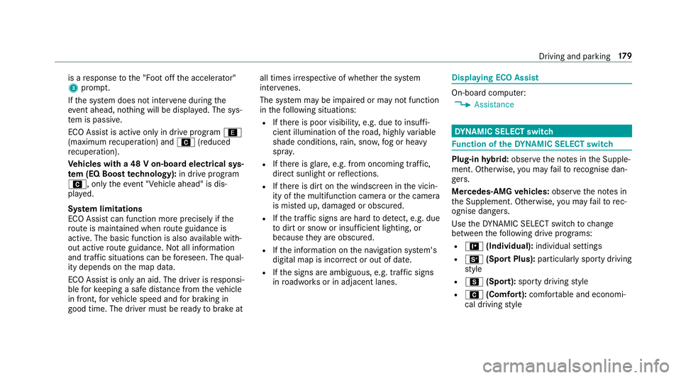
is a
response tothe "Foot off the accelerator"
3 prom pt.
If th e sy stem does not inter vene du ring the
eve nt ahead, no thing will be displa yed. The sys‐
te m is passive.
ECO Assist is active only in drive program ;
(maximum recuperation) and A(reduced
re cuperation).
Ve hicles with a 48 V on-board electrical sys‐
te m (EQ Boo sttech nology): in drive program
A, only theeve nt "Vehicle ahead" is dis‐
pl ay ed.
Sy stem limitations
ECO Assist can function more precisely if the
ro ute is main tained when route guidance is
active. The basic function is also available with‐
out active route guidance. Notall information
and traf fic situations can be fore seen. The qual‐
ity depends on the map data.
ECO Assist is only an aid. The driver is responsi‐
ble forke eping a safe dis tance from theve hicle
in front, forve hicle speed and for braking in
good time. The driver must be ready tobrake at all times ir
respective of whe ther the sy stem
inter venes.
The sy stem may be impaired or may not function
in thefo llowing situations:
R Ifth ere is poor visibility, e.g. due toinsuf fi‐
cient illumination of thero ad, high lyvariable
shade conditions, rain, sno w,fog or heavy
spr ay.
R Ifth ere is glare, e.g. from oncoming traf fic,
di re ct sunlight or reflections.
R Ifth ere is dirt on the windscreen in the vicin‐
ity of the multifunction camera or the camera
is mis ted up, damaged or obscured.
R Ifth e traf fic signs are ha rdtodetect, e.g. due
to dirt or snow or insuf ficient lighting, or
because they are obscured.
R Ifth e information on the navigation sy stem's
digital map is incor rect or out of da te.
R Ifth e signs are ambiguous, e.g. traf fic signs
in roadwor ksor in adjacent lanes. Displaying ECO Assist
On-board computer:
0018 Assistance DY
NA MIC SELECT switch Fu
nction of theDY NA MIC SELECT switch Plug-in
hybrid: obser vethe no tes in the Supple‐
ment. Otherwise, you may failto recognise dan‐
ge rs.
Mercedes-AMG vehicles: observeth e no tes in
th e Supplement. Otherwise, you may failto rec‐
ognise dangers.
Use theDY NA MIC SELECT switch tochange
between thefo llowing drive programs:
R = (Individual): individual settings
R B (Sport Plus): particularlysporty driving
st yle
R C (Sport): sporty driving style
R A (Comfort): comfortable and economi‐
cal driving style Driving and pa
rking 17 9
Page 207 of 609
R
theBattery charge insufficient for standby
mode message appears in the multimedia
sy stem displa y.
0009 Standby mode is automatically deactivated
when the ignition is switched on.
Ac tivating/deactivating standby mode
Multimedia sy stem:
0018 Vehicle 0019
î Vehicle settings
0019 Standby mode
0009 This function is not available for all models. 0007
Activate 0073or deacti vate 0053 the function.
When you activate the function, a prom pt
appears. 0007
Select Yes.
St andby mode is activated. Driving and driving saf
ety sy stems Driving sy
stems and your responsibility Yo
ur vehicle is equipped with driving sy stems
which assist you in driving, parking and manoeu‐
vring theve hicle. The driving sy stems are aids and do not
relie ve you of your responsibility per‐
ta ining toroad traf fic la w.Pay attention tothe
traf fic conditions at all times and inter vene
when necessa ry. Be aware of the limitations
re ga rding the safe use of these sy stems. Fu
nction of thera dar senso rs Some driving and driving sa
fety sy stems use
ra dar sensors tomonitor the area in front of,
behind or next totheve hicle (depending on the
ve hicle's equipment).
Depending on theve hicle's equipment, thera dar
sensors are integrated behind the bumpers
and/or behind the Mercedes star. Keep these
parts free of dirt, ice and slush
(0013 page 422). The sensors must not be cov‐
ered, forex ample bycycle rack s, overhanging
loads, sticke rs,fo il or foils toprotect against
st one chipping. In theeve nt of dama getothe
bumpers or radiator grille, or following a collision
impacting the bumpers or radiator grille, ha ve
th e function of thera dar sensors checked at a
qu alified specialist workshop. The driver assis‐
ta nce sy stem may no longer workproper ly. Overview of driving sy
stems and driving
saf ety sy stems In
this section, you will find information about
th efo llowing driving sy stems and driving saf ety
sy stems:
R 360° Camera (0013 page244)
R ABS ( Anti-lo ckBra king System)
(0013 page 205)
R Active Dis tance Assi stDISTRONIC
(0013 page 220)
R Adaptive brake lights (0013 page216)
R AIRMATIC (0013 page 234)
R Active Brake Assi st (0013 page210)
R Active Lane Keeping Assist (0013 page 261)
R ATTENTION ASSIST (0013 page 254)
R BAS (B rake Assist System) (0013 page 205)
R Hill Start Assist (0013 page 232)
R DYNA MIC BODY CONTROL (0013 page 234)
R EBD ( Electronic Brakeforc eDistribution)
(0013 page 209) 204
Driving and parking