warning light MERCEDES-BENZ C-CLASS ESTATE 2020 Owner's Manual
[x] Cancel search | Manufacturer: MERCEDES-BENZ, Model Year: 2020, Model line: C-CLASS ESTATE, Model: MERCEDES-BENZ C-CLASS ESTATE 2020Pages: 565, PDF Size: 10.27 MB
Page 122 of 565
Pa
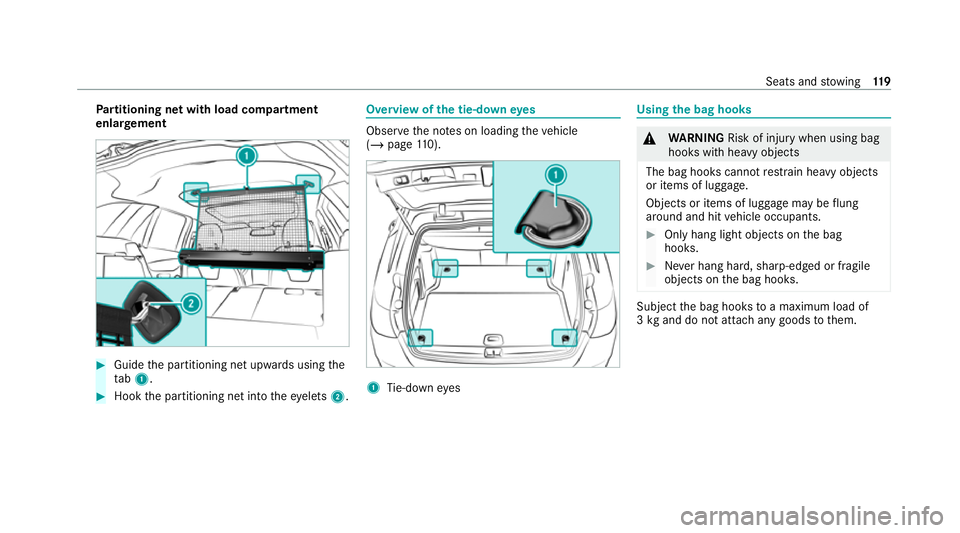
rtitioning net with load compartment
enlar gement #
Guide the partitioning net upwards using the
ta b1. #
Hook the partitioning net into theey elets 2. Overview of
the tie-down eyes Obser
vethe no tes on loading theve hicle
(/ page 110). 1
Tie-down eyes Using
the bag hooks &
WARNING Risk of injury when using bag
hooks with heavy objects
The bag hooks cannot restra in heavy objects
or items of luggage.
Objects or items of luggage may be flung
around and hit vehicle occupants. #
Only hang light objects on the bag
hooks. #
Never hang hard, sharp-edged or fragile
objects on the bag hooks. Subject
the bag hooks toa maximum load of
3 kg and do not attach any goods tothem. Seats and
stowing 11 9
Page 123 of 565
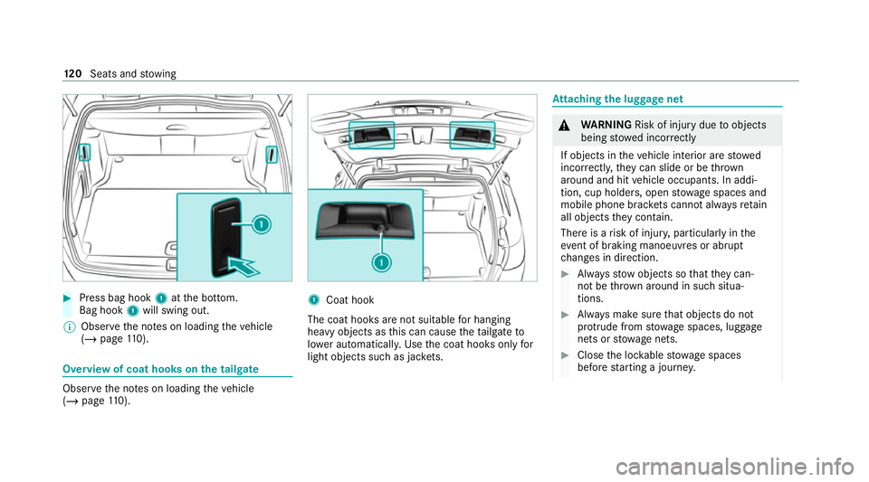
#
Press bag hook 1atthe bottom.
Bag hook 1will swing out.
% Obser vethe no tes on loading theve hicle
(/ page 110). Overvi
ewof coat hooks on the tailgate Obser
vethe no tes on loading theve hicle
(/ page 110). 1
Coat hook
The coat hoo ksare not suitable for hanging
heavy objects as this can cause theta ilgate to
lo we r auto matical ly. Use the coat hooks only for
light objects such as jac kets. At
taching the luggage net &
WARNING Risk of injury duetoobjects
being stowed incor rectly
If objects in theve hicle interior are stowed
incor rectly, they can slide or be thrown
around and hit vehicle occupants. In addi‐
tion, cup holders, open stowage spaces and
mobile phone brac kets cann otalw aysre tain
all objects they contain.
The reis a risk of injur y,particularly in the
ev ent of braking manoeuvres or abrupt
ch anges in direction. #
Alw aysstow objects so that they can‐
not be throw n around in su chsitua‐
tions. #
Alw ays make sure that objects do not
pr otru de from stowage spaces, luggage
nets or stowage nets. #
Close the loc kable stow age spaces
before starting a journe y.12 0
Seats and stowing
Page 127 of 565
&
DANG ER Risk of fata l injury due toincor‐
re ct handling of the soc ket
Yo u could recei vean electric shock in partic‐
ular:
R ifyo ure ach into the soc ket.
R ifyo u insert unsuitable devices or objects
into the soc ket. #
Do not reach into the soc ket. #
Only connect suitable devices tothe
soc ket. Re
quirements:
R Devices are equipped with a suitable plug
which con form sto thest andards specific to
th e count ryyou are in.
R A device up toa maximum of 150 W (0.65 A)
is used.
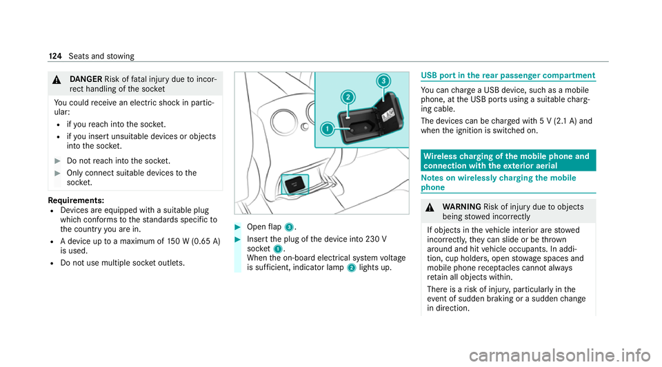
R Do not use multiple soc ket outlets. #
Open flap 3. #
Insert the plug of the device into 230 V
soc ket1.
When the on-board electrical sy stem voltage
is suf ficient, indicator la mp2lights up. USB port in
there ar passenger comp artment Yo
u can charge a USB device, such as a mobile
phone, at the USB ports using a suitable charg‐
ing cable.
The devices can be charge d with 5 V (2.1 A) and
when the ignition is switched on. Wire
lesscharging of the mobile phone and
connection with theex terior aerial Note
s on wirelessly charging the mobile
phone &
WARNING Risk of injury duetoobjects
being stowed inco rrectly
If objects in theve hicle interior are stowed
incor rectly, they can slide or be thrown
around and hit vehicle occupants. In addi‐
tion, cup holders, open stowage spaces and
mobile phone recep tacles cannot al ways
re tain all objects within.
There is a risk of injur y,particularly in the
ev ent of sudden braking or a sudden change
in direction. 124
Seats and stowing
Page 132 of 565
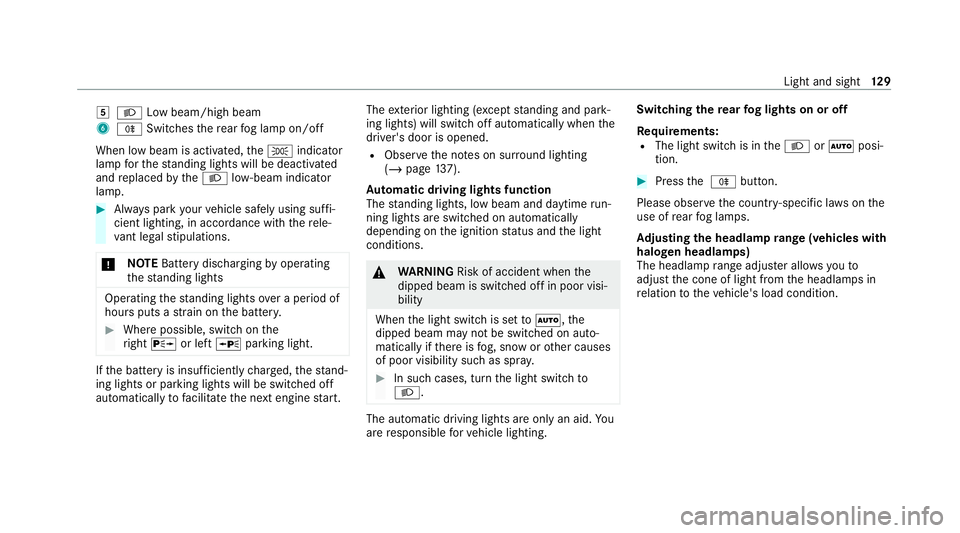
5
L Low beam/high beam
6 R Switches there ar fog lamp on/off
When low beam is activated, theT indicator
lamp forth est anding lights will be deactivated
and replaced bytheL low- beam indicator
lamp. #
Alw ays park your vehicle safely using suf fi‐
cient lighting, in acco rdance with there le‐
va nt le galst ipulations.
* NO
TEBattery discharging byoperating
th est anding lights Operating
thest anding lights over a period of
hours puts a stra in on the batter y. #
Where possible, switch on the
ri ght X or left Wparking light. If
th e battery is insuf ficiently charge d, thest and‐
ing lights or parking lights will be swit ched off
automatically tofacilitate the next engine start. The
exterior lighting (e xcept standing and park‐
ing lights) will swit choff automatically when the
driver's door is opened.
R Obser vethe no tes on sur round lighting
(/ page 137).
Au tomatic driving lights function
The standing lights, low beam and daytime run‐
ning lights are switched on au tomatically
depending on the ignition status and the light
conditions. &
WARNING Risk of accident when the
dipped beam is switched off in poor visi‐
bility
When the light switch is set toà ,the
dipped beam may not be switched on auto‐
matically if there is fog, snow or other causes
of poor visibility such as spr ay. #
In such cases, turn the light switch to
L . The automatic driving lights are only an aid.
Yo u
are responsible forve hicle lighting. Switching
there ar fog lights on or off
Re quirements:
R The light switch is in theL orà posi‐
tion. #
Press the R button.
Please obser vethe count ry-specific la wsonthe
use of rear fog lamps.
Ad justing the headlamp range (vehicles with
halogen headla mps)
The headlamp range adjus ter allows youto
adjust the cone of light from the headlamps in
re lation totheve hicle's load condition. Light and sight
12 9
Page 134 of 565
Tu
rn signal light #
Toindicate briefl y:push the combination
switch briefly tothe point of resis tance in the
direction of ar row2or4.
The cor responding turn signal light will flash
th re e times. #
Toindicate permanentl y:push the combi‐
nation switch be yond the point of resis tance
in the direction of ar row2or4. Ac
tivating/deactivating the hazard warning
lights #
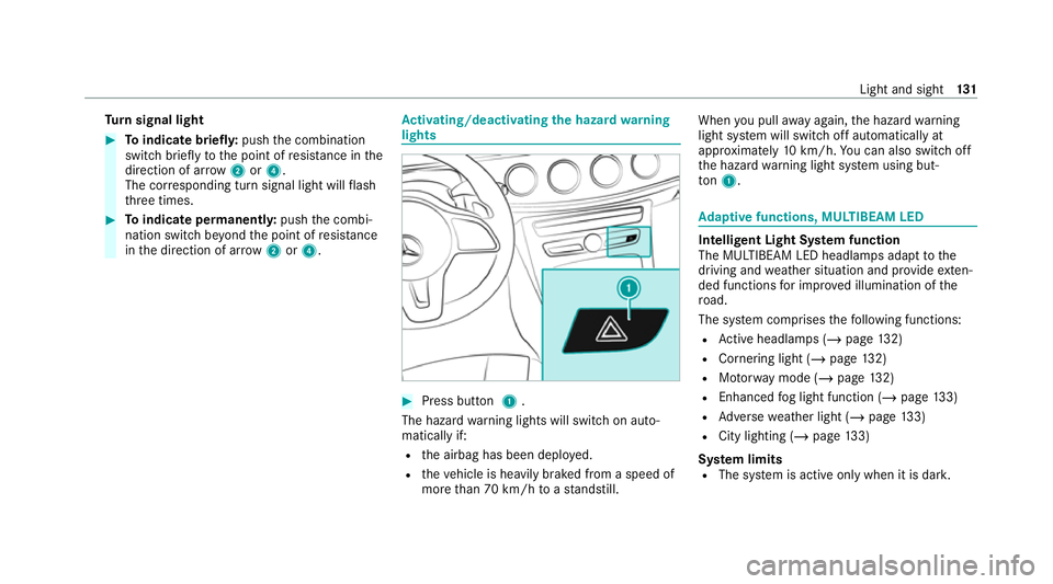
Press button 1.
The hazard warning lights will switch on auto‐
matically if:
R the airbag has been deplo yed.
R theve hicle is heavily braked from a speed of
more than 70 km/h toast andstill. When
you pull away again, the hazard warning
light sy stem will switch off automatically at
appr oximately 10km/h. You can also swit choff
th e hazard warning light sy stem using but‐
to n1. Ad
aptive functions, MULTIBEAM LED Intelligent Light Sy
stem function
The MULTIBEAM LED headlamps adapt tothe
driving and weather situation and pr ovide exten‐
ded functions for impr oved illumination of the
ro ad.
The sy stem comprises thefo llowing functions:
R Active headla mps (/ page132)
R Cornering light (/ page132)
R Motorw ay mode (/ page132)
R Enhanced fog light function (/ page133)
R Adversewe ather light (/ page133)
R City lighting ( /page 133)
Sy stem limits
R The sy stem is active only when it is dar k. Light and sight
131
Page 136 of 565
R
the GPS
The function is not active in thefo llowing cases:
R at speeds below 80 km/h.
Enhanced fog light function
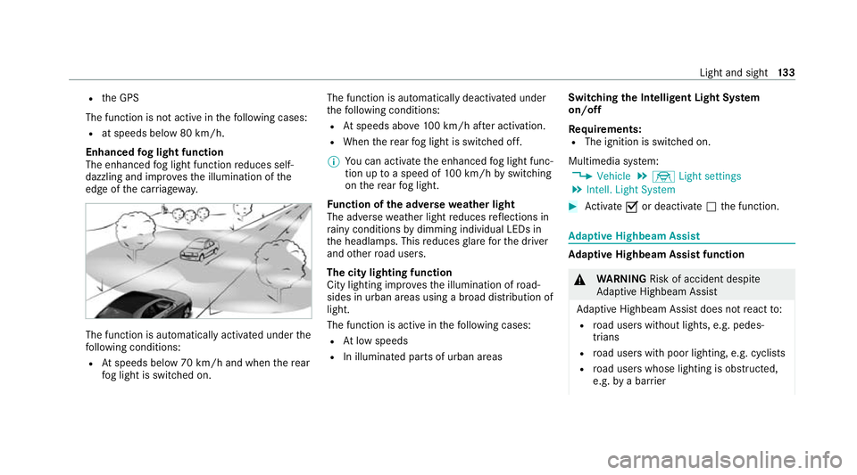
The enhanced fog light function reduces self-
dazzling and impr ovesth e illumination of the
edge of the car riag ewa y. The function is automatically activated under
the
fo llowing conditions:
R Atspeeds below 70 km/h and when there ar
fo g light is switched on. The function is automatically deactivated under
th
efo llowing conditions:
R Atspeeds abo ve100 km/h af ter activation.
R When there ar fog light is switched off.
% You can activate the enhanced fog light func‐
tion up toa speed of 100 km/h byswitching
on there ar fog light.
Fu nction of the ad versewe ather light
The adverse weather light reduces reflections in
ra iny conditions bydimming individual LEDs in
th e headlamps. This reduces glare forth e driver
and other road users.
The city lighting function
City lighting impr oves the illumination of road‐
sides in urban areas using a broad distribution of
light.
The function is active in thefo llowing cases:
R Atlow speeds
R In illuminated parts of urban areas Switching
the Intelligent Light Sy stem
on/off
Re quirements:
R The ignition is switched on.
Multimedia sy stem:
4 Vehicle 5
÷ Light settings
5 Intell. Light System #
Activate Oor deacti vate ª the function. Ad
aptive Highbeam Assist Ad
aptive Highbeam Assist function &
WARNING Risk of accident despite
Ad aptive Highbeam Assist
Ad aptive Highbeam Assist does not react to:
R road users without lights, e.g. pedes‐
trians
R road users with poor lighting, e.g. cyclists
R road users whose lighting is obstructed,
e.g. bya bar rier Light and sight
13 3
Page 138 of 565
Ad
aptive Highbeam Assist Plus Ad
aptive Highbeam Assist Plus function &
WARNING Risk of accident despite
Ad aptive Highbeam Assist Plus
Ad aptive Highbeam Assist Plus does not
re act to:
R road users without lights, e.g. pedes‐
trians
R road users with poor lighting, e.g. cyclists
R road users whose lighting is obstructed,
e.g. bya bar rier
On very rare occasions, Adaptive Highbeam
Assist Plus may failto recognise other road
users with their own lighting, or may recog‐
nise them too late.
In these, or in similar situations, the auto‐
matic high beam will not be deactivated or
will be activated despite the presence of
ot her road users. #
Alw ays obser vethero ad and traf fic
conditions carefully and switch off the
high beam in good time. Ad
aptive Highbeam Assist Plus cannot take into
account road, weather or traf fic conditions.
De tection may be restricted in thefo llowing
cases:
R In poor visibilit y,e.g. fog, heavy rain or snow
R ifth ere is dirt on the sensors or the sensors
are obscured
Ad aptive Highbeam Assist Plus is on lyan aid.
Yo u are responsible for adju sting theve hicle's
lighting tothe pr evailing light, visibility and traf‐
fi c conditions. Ad
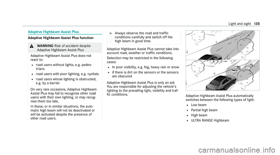
aptive Highbeam Assist Plus automatically
swit ches between thefo llowing types of light:
R Low beam
R Partial high beam
R High beam
R ULTRA RANGE Highbeam Light and sight
13 5
Page 141 of 565
Ad
justing the brightness #
Select Brightness . #
Set a brightness value.
Ac tivating the brightness for zones #
Select Brightness zones .#
Activate Oor deacti vate ª the function.
The Display ,Front andRear zones can be set
separately. Setting
the interior lighting switch-off delay
time Multimedia sy
stem:
4 Vehicle 5
÷ Light settings
5 Interior light shut-off #
Set the switch-off delay time. Changing bulbs (only
forve hicles with halo‐
ge n headla mps) Note
s onchanging bulbs &
WARNING Risk of burn s from hot com‐
ponent parts whilst replacing a bulb
Bulbs, lamps and plugs can become very hot
during operation.
When replacing a bulb, you could burn your‐
self on these component parts. #
Allow the component parts tocool
down before replacing the bulb. R
Do not use a bulb if it has been dropped or if
itsglass has been sc ratched. The bulb may
ot herwise explode.
R Do not touch theglass bulb with your bare
hands.
R Protect bulbs from moisture and do not allow
bulbs tocome into contact wi thliquids. Overview of
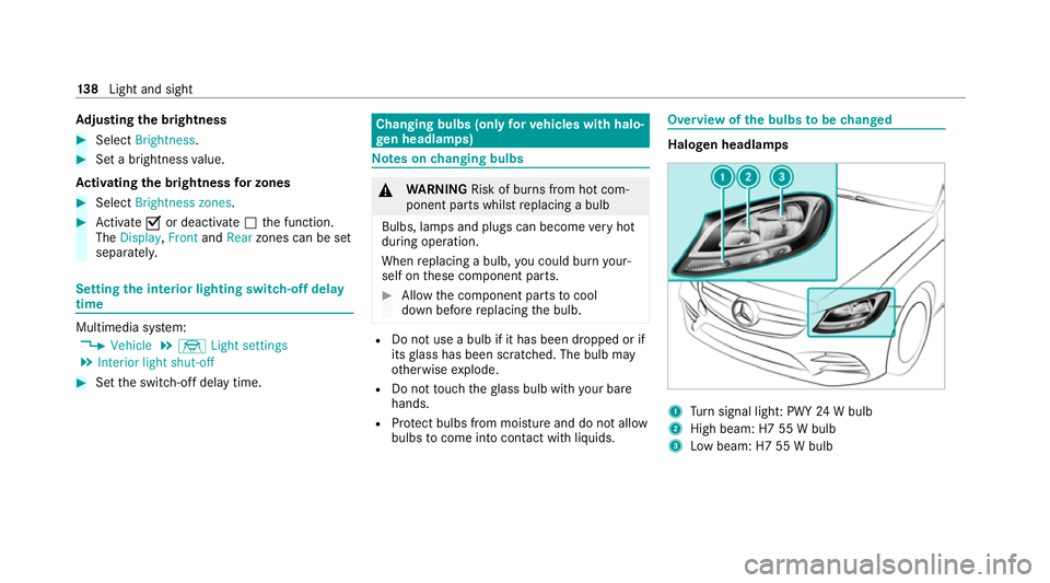
the bulbs tobe changed Halogen headlamps
1
Turn signal light: PWY 24W bulb
2 High beam: H7 55 W bulb
3 Low beam: H7 55 W bulb 13 8
Light and sight
Page 147 of 565
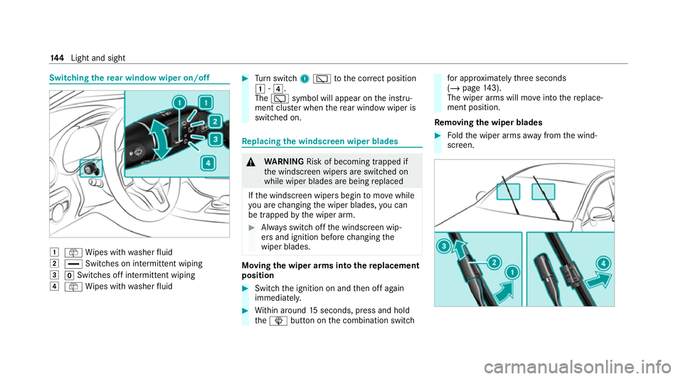
Switching
there ar window wiper on/off 1
ô Wipes with washer fluid
2 ° Switches on intermittent wiping
3 gSwitches off intermittent wiping
4 ô Wipes with washer fluid #
Turn switch 1è tothe cor rect position
1 -4.
The è symbol will appear on the instru‐
ment clus ter when there ar wind owwiper is
swit ched on. Re
placing the windsc reen wiper blades &
WARNING Risk of becoming trapped if
th e windscreen wipers are switched on
while wiper blades are being replaced
If th e windscreen wipers begin tomo vewhile
yo u are changing the wiper blades, you can
be trapped bythe wiper arm. #
Alw ays switch off the windscreen wip‐
ers and ignition before changing the
wiper blades. Moving
the wiper arms into there placement
position #
Switch the ignition on and then off again
immediatel y. #
Within around 15seconds, press and hold
th eî button on the combination switch fo
r appro ximately thre e seconds
(/ page 143).
The wiper arms will mo veinto there place‐
ment position.
Re moving the wiper blades #
Foldthe wiper arms away from the wind‐
screen. 14 4
Light and sight
Page 149 of 565
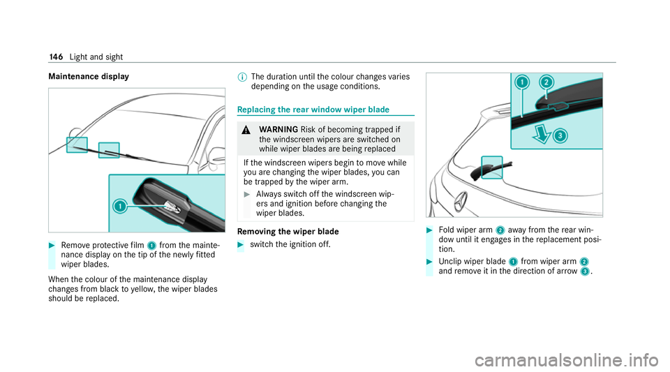
Maintenance display
#
Remo veprotective film 1 from the mainte‐
nance display on the tip of the newly fitted
wiper blades.
When the colour of the maintenance display
ch anges from black to yellow, the wiper blades
should be replaced. %
The duration until the colour changes varies
depending on the usage conditions. Re
placing the rear window wiper blade &
WARNING Risk of becoming trapped if
th e windscreen wipers are switched on
while wiper blades are being replaced
If th e windscreen wipers begin tomo vewhile
yo u are changing the wiper blades, you can
be trapped bythe wiper arm. #
Alw ays switch off the windscreen wip‐
ers and ignition before changing the
wiper blades. Re
moving the wiper blade #
switch the ignition off. #
Fold wiper arm 2away from there ar win‐
dow until it engages in there placement posi‐
tion. #
Unclip wiper blade 1from wiper arm 2
and remo veit in the direction of ar row 3. 14 6
Light and sight