turn signal MERCEDES-BENZ C-CLASS SALOON 2012 Owners Manual
[x] Cancel search | Manufacturer: MERCEDES-BENZ, Model Year: 2012, Model line: C-CLASS SALOON, Model: MERCEDES-BENZ C-CLASS SALOON 2012Pages: 557, PDF Size: 10.15 MB
Page 14 of 557
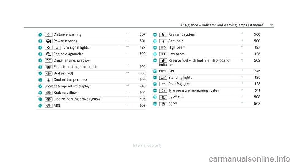
1
L Distance warning →
507
2 Ð Powe rst eering →
501
3 #! Turn signal lights →
127
4 ; Engine diagnostics →
502
5 % Diesel engine: preglow
6 ! Electric pa rking brake (red) →
505
7 J Brakes (red) →
505
8 ÿ Coolant temp erature →
502
9 Coolant temp erature display →
24 5
A J Brakes (yellow) →
505
B ! Electric parking brake (yell ow)→
505
C ! ABS →
508 D
6 Restra int sy stem →
500
E ü Seat belt →
500
F K High beam →
127
G L Low beam →
12 5
H 8 Reser vefuel with fuel filler flap location
indicator →
502
I Fuel le vel →
24 5
J T Standing lights →
12 5
K R Rear fog light →
12 6
L h Tyre pressure monitoring sy stem →
511
M å ESP®
OFF →
508
N ÷ ESP®
→
508 At
aglance – Indicator and warning lamps (s tanda rd) 11
Internal use only
Page 16 of 557
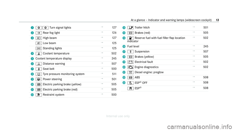
1
#! Turn signal lights →
127
2 R Rear fog light →
12 6
3 K High beam →
127
L Low beam →
12 5
T Standing lights →
12 5
4 ÿ Coolant temp erature →
502
5 Coolant temp erature display →
24 5
6 L Distance warning →
507
7 ü Seat belt →
500
8 h Tyre pressure monitoring sy stem →
511
9 Ù Powe rst eering →
501
A ! Electric pa rking brake (yellow) →
505
B ! Electric parking brake (red) →
505
C 6 Restra int sy stem →
500 D
ï Trailer hit ch →
501
E J Brakes (red) →
505
F 8 Reser vefuel with fuel filler flap location
indicator →
502
G Fuel le vel →
24 5
H ä Suspension →
507
I J Brakes (yellow) →
505
J # Electrical fault →
502
K ; Engine diagnostics →
502
L % Diesel engine: preglow
M ! ABS →
508
N å ESP®
OFF →
508
÷ ESP®
→
508 At
aglance – Indicator and warning lamps (widesc reen cockpit) 13
Internal use only
Page 82 of 557

There is in
terference from a po werful radio
signal source.
The KEYLESS-GO function is impaired by,for
ex ample:
R high voltage po wer lines
R mobile phones
R electronic devices (no tebooks, tablets)
R shielding due tome tal objects or induction
loops for electrical gate systems or auto‐
matic bar riers #
Make sure that there is suf ficient dist ance
between theke y and the po tential sou rce of
inter fere nce. Ac
tivating/deactivating the automatic lo ck‐
ing feature The
vehicle is loc ked automatically when the
ignition is switched on and the wheels are turn‐
ing fast erthan walking pace. #
Toactivate: press and hold button 2for
appr oximately five seconds until an acoustic
signal sounds. #
Todeactivate: press and hold button 1for
appr oximately five seconds until an acoustic
signal sounds. In
thefo llowing situations, there is a danger of
being loc ked out when the function is activated:
R While theve hicle is being tow star ted/
pushed.
R Ifth eve hicle is being tested on a roller dyna‐
mome ter. Locking/unlocking
the driver's door with the
emer gency key %
Ifyo u wish tolock theve hicle entirely using
th e emer gency key,firs t press the button for
locking from the inside while the driver's
door is open. Then proceed tolock the driv‐
er's door using the emer gency key. Opening and closing
79
Internal use only
Page 130 of 557
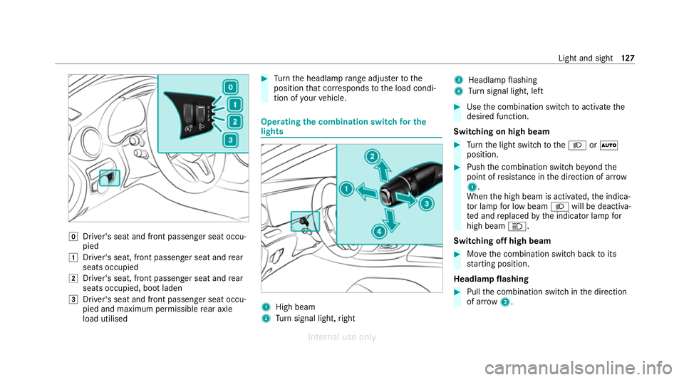
g
Driver's seat and front passenger seat occu‐
pied
1 Driver's seat, front passenger seat and rear
seats occupied
2 Driver's seat, front passenger seat and rear
seats occupied, boot laden
3 Driver's seat and front passenger seat occu‐
pied and maximum permissible rear axle
load utilised #
Turn the headlamp range adjus terto the
position that cor responds tothe load condi‐
tion of your vehicle. Operating
the combination switch for the
lights 1
High beam
2 Turn signal light, right 3
Headlamp flashing
4 Turn signal light, left #
Use the combination switch toactivate the
desired function.
Switching on high beam #
Turn the light switch totheL orÃ
position. #
Push the combination switch be yond the
point of resis tance in the direction of ar row
1 .
When the high beam is activated, the indica‐
to r lamp for low beam Lwill be deactiva‐
te d and replaced bythe indicator lamp for
high beam K.
Switching off high beam #
Movethe combination switch back toits
st arting position.
Headla mpflashing #
Pull the combination switch in the direction
of ar row3. Light and sight
127
Internal use only
Page 131 of 557
Tu
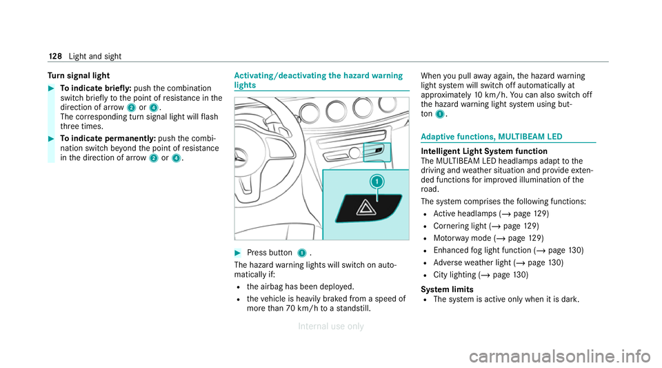
rn signal light #
Toindicate briefl y:push the combination
switch briefly tothe point of resis tance in the
direction of ar row2or4.
The cor responding turn signal light will flash
th re e times. #
Toindicate permanentl y:push the combi‐
nation switch be yond the point of resis tance
in the direction of ar row2or4. Ac
tivating/deactivating the hazard warning
lights #
Press button 1.
The hazard warning lights will switch on auto‐
matically if:
R the airbag has been deplo yed.
R theve hicle is heavily braked from a speed of
more than 70 km/h toast andstill. When
you pull away again, the hazard warning
light sy stem will switch off automatically at
appr oximately 10km/h. You can also swit choff
th e hazard warning light sy stem using but‐
to n1. Ad
aptive functions, MULTIBEAM LED Intelligent Light Sy
stem function
The MULTIBEAM LED headlamps adapt tothe
driving and weather situation and pr ovide exten‐
ded functions for impr oved illumination of the
ro ad.
The sy stem comprises thefo llowing functions:
R Active headla mps (/ page129)
R Cornering light (/ page129)
R Motorw ay mode (/ page129)
R Enhanced fog light function (/ page130)
R Adversewe ather light (/ page130)
R City lighting (/ page130)
Sy stem limits
R The sy stem is active only when it is dar k.12 8
Light and sight
Internal use only
Page 138 of 557
Ad
justing the brightness #
Select Brightness . #
Set a brightness value.
Ac tivating the brightness for zones #
Select Brightness zones . #
Activate Oor deacti vate ª the function.
The Display ,Front andRear zones can be set
separately. Setting
the interior lighting switch-off delay
time Multimedia sy
stem:
4 Vehicle 5
÷ Light settings
5 Interior light shut-off #
Set the switch-off delay time. Changing bulbs (only
forve hicles with halo‐
ge n headla mps) Note
s onchanging bulbs &
WARNING Risk of burn s from hot com‐
ponent parts whilst replacing a bulb
Bulbs, lamps and plugs can become very hot
during operation.
When replacing a bulb, you could burn your‐
self on these component parts. #
Allow the component parts tocool
down before replacing the bulb. R
Do not use a bulb if it has been dropped or if
itsglass has been sc ratched. The bulb may
ot herwise explode.
R Do not touch theglass bulb with your bare
hands.
R Protect bulbs from moisture and do not allow
bulbs tocome into contact wi thliquids. Overview of
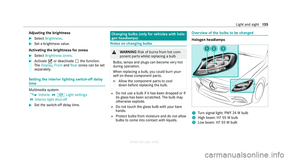
the bulbs tobe changed Halogen headlamps
1
Turn signal light: PWY 24W bulb
2 High beam: H7 55 W bulb
3 Low beam: H7 55 W bulb Light and sight
13 5
Internal use only
Page 139 of 557
Ta
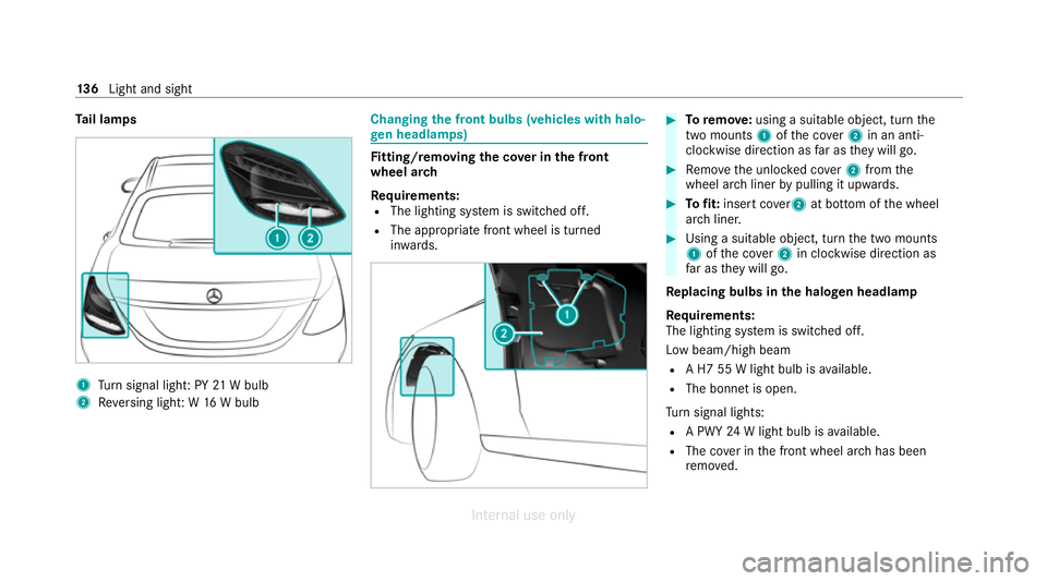
il lamps 1
Turn signal light: PY 21W bulb
2 Reversing light: W 16W bulb Changing
the front bulbs (vehicles with halo‐
ge n headla mps) Fi
tting/ removing the co ver in the front
wheel ar ch
Re quirements:
R The lighting sy stem is switched off.
R The appropriate front wheel is turned
inwa rds. #
Toremo ve:using a suitable object, turn the
two mounts 1ofthe co ver2 in an anti-
clockwise direction as far as they will go. #
Remo vethe unloc ked co ver2 from the
wheel ar chliner bypulling it upwards. #
Tofit: inse rtco ver 2 at bottom of the wheel
ar ch liner. #
Using a suitable object, turn the two mounts
1 ofthe co ver2 in clockwise direction as
fa r as they will go.
Re placing bulbs in the halo gen headla mp
Re quirements:
The lighting sy stem is switched off.
Low beam/high beam
R A H7 55 W light bulb is available.
R The bonnet is open.
Tu rn signal lights:
R A PWY 24W light bulb is available.
R The co ver in the front wheel ar chhas been
re mo ved. 13 6
Light and sight
Internal use only
Page 140 of 557
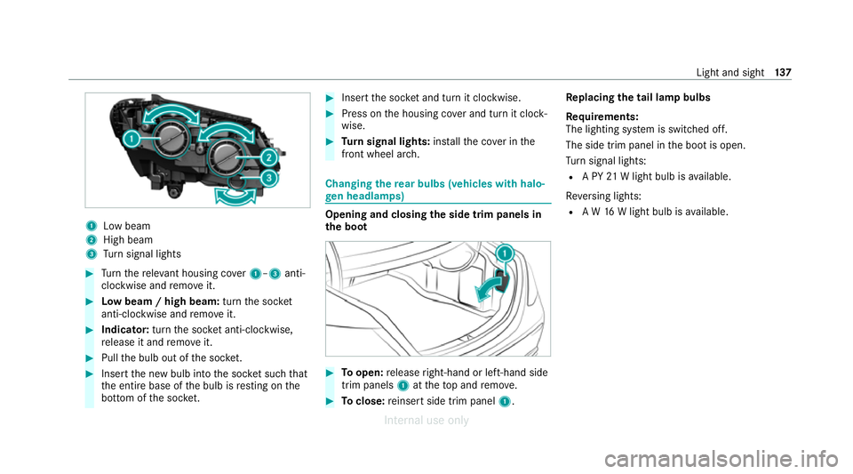
1
Low beam
2 High beam
3 Turn signal lights #
Turn there leva nt housing co ver1–3 anti-
clockwise and remo veit. #
Low beam / high beam: turnthe soc ket
anti-clockwise and remo veit. #
Indicator: turnthe soc ket anti-clo ckwise,
re lease it and remo veit. #
Pull the bulb out of the soc ket. #
Inse rtthe new bulb into the soc ket su chthat
th e entire base of the bulb is resting on the
bottom of the soc ket. #
Inse rtthe soc ket and turn it clo ckwise. #
Press on the housing co ver and turn it clock‐
wise. #
Turn signal lights: installth e co ver in the
front wheel ar ch. Changing
there ar bulbs (vehicles with halo‐
ge n headla mps) Opening and closing
the side trim panels in
th e boot #
Toopen: release right-hand or left-hand side
trim panels 1attheto p and remo ve. #
Toclose: reinse rtside trim panel 1.Re
placing the tail lamp bulbs
Re quirements:
The lighting sy stem is switched off.
The side trim panel in the boot is open.
Tu rn signal lights:
R A PY 21W light bulb is available.
Re versing lights:
R A W 16W light bulb is available. Light and sight
137
Internal use only
Page 200 of 557
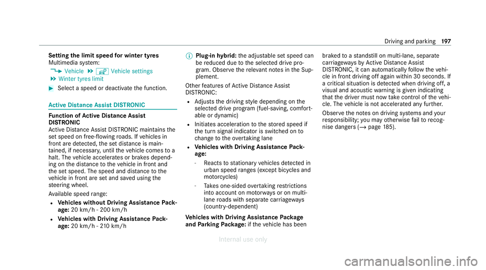
Setting
the limit speed for winter tyres
Multimedia sy stem:
4 Vehicle 5
î Vehicle settings
5 Winter tyres limit #
Select a speed or deactivate the function. Ac
tive Di stance Assist DISTRO NICFu
nction of Active Di stance Assist
DISTRO NIC
Ac tive Dis tance Assi stDISTRONIC maintains the
set speed on free-flowing roads. If vehicles in
front are de tected, the set dis tance is main‐
ta ined, if necessar y,until theve hicle comes to a
halt. The vehicle accelerates or brakes depend‐
ing on the dis tance totheve hicle in front and
th e set speed. The speed and dis tance tothe
ve hicle in front are set and sa ved using the
st eering wheel.
Av ailable speed range:
R Vehicles without Driving Assistance Pack‐
age: 20 km/h - 200 km/h
R Vehicles with Driving Assistance Pack‐
age: 20 km/h - 210 km/h %
Plug-in hybrid: the adjus table set speed can
be reduced due tothe selected drive pro‐
gram. Obser vethere leva nt no tes in the Sup‐
plement.
Other features of Active Dis tance Assi st
DISTRONIC:
R Adjusts the driving style depending on the
selected drive program (fuel-saving, comfort‐
able or dynamic)
R Initiates acceleration tothestored speed if
th e turn signal indicator is switched on to
ch ange totheove rtaking lane
R Vehicles with Driving Assistance Pack‐
age:
- Reacts tostationary vehicles de tected in
urban speed ranges (e xcept bicycles and
mo torcyc les)
- Take s one-sided overtaking restrictions
into account on mo torw ays or on multi-
lane roads with separate car riag ew ays
(countr y-dependent)
Ve hicles with Driving Assistance Package
and Park ingPackage: ifth eve hicle has been braked
toast andstill on multi-lane, separate
car riag ewa ysby Active Dis tance Assi st
DISTRONIC, it can au tomatically follow theve hi‐
cle in front driving off again within 30 seconds. If
a critical situation is de tected when driving off, a
visual and acoustic warning is given indicating
th at the driver must now take control of theve hi‐
cle. The vehicle is not accelerated any fur ther.
Obser vethe no tes on driving sy stems and your
re sponsibility; you may otherwise failto recog‐
nise dangers (/ page 185). Driving and pa
rking 197
Internal use only
Page 205 of 557
proper
lyde tected bythe sy stem. The maximum
permissible speed applying toave hicle with a
trailer is not de tected bythe sy stem.
Ad just the speed in these situations. &
WARNING Risk of accident due toActive
Speed Limit Assi stadapting theve hicle's
speed
The speed adop tedby Active Speed Limit
Assi stmay be too high or incor rect in some
individual cases, su chas:
R at speed limits below 20 km/h
R inwe t conditions or in fog
R when towing a trailer #
Ensure that the driven speed complies
with traf fic re gulations. #
Adjust the driving speed tosuit cur rent
traf fic and weather conditions. Fu
nction of route-based speed adaptation
When Active Dis tance Assi stDISTRONIC is acti‐
va ted, theve hicle speed will be adap ted accord‐
ingly tothero ute events ahead. Depending on th
e drive prog ram selected, theve hicle negoti‐
ates a route event ahead in an economical, com‐
fo rtable or dynamic manner. When thero ute
eve nt has been passed, theve hicle accelerates
again tothestored speed. The set dis tance to
th eve hicle in front, vehicles de tected ahead and
speed restrictions ahead are take n into account.
Yo u can activate and deactivate route-based
speed adap tation in the multimedia sy stem
(/ page 203).
The following route events are take n into
account:
R Bends
R T-junctions, roundabouts and tollst ations
R Turns and exits
R Traf fic jams ahead (only wi thLive Traf fic
Information (/ page 304))
% When theto llst ation is reached, Active Dis‐
ta nce Assi stDISTRONIC adopts the speed as
th estored speed. Also,
the speed is reduced if the turn signal indi‐
cator tochange lanes is swit ched on and one of
th efo llowing situations is de tected:
R Turning off at junctions
R Driving on slowing-down lanes
R Driving on lanes adjacent toslowing-down
lanes
The driver is responsible forch oosing theright
speed and observing other road users. This
applies in particular tojunctions, roundabouts
and traf fic lights, as route-based speed adap ta‐
tion does not brake theve hicle toast andstill.
When route guidance is active, thefirs t speed
adjustment is car ried out automatically. If the
turn signal indica tor is switched on, the selected
ro ute is confirmed and fur ther speed adjustment
is activated.
Speed adap tation is cancelled in thefo llowing
cases:
R Ifth e turn signal indicator is switched off
before thero ute event.
R Ifth e driver depresses the accelerator or
brake pedal during the process. 202
Driving and parking
Internal use only